© 2018, IRJET | Impact Factor value: 6.171 | ISO 9001:2008 Certified Journal | Page 3507
“All TERRAIN VEHICLE FOR DEFENCE”
Kumavat Yogesh Narayan
1, Kankal Darshan Makrand
2,Ghadage Shital Kisan
3,
Ingale Vinaya Shivaji
41,2,3,4
Jaiwant Shikshan Prasarak Mandal’s, Bhivrabai Sawant Institute of Technology & Research,
Wagholi, Pune, India
---***---Abstract
— ATV stands for All Terrain Vehicle. As a new classof vehicle, they are made to go to terrains which would be difficult for normal vehicles. If used for technical research these vehicles may carry equipment’s also troops. The main objective of developing such a vehicle is for defense purpose. The primary mechanical purpose of the vehicle design is its drive vehicle in simple way, which is highly skilled by using only individual motors for ability to move or move freely and easily. All motors are located inside the wheels where thermal variation is kept to a minimum, increasing more efficiency. It can climb 60-70 degree reach at highest given point without much hassle. As the development is done for a specific purpose of defense requirements this vehicle is more prone to application as per need be.
Keywords
—rocker boggie suspension , defense , all terrain vehicle , unmanned vehicle, Wheel type mobile robot; Stair climbing.I. INTRODUCTION
In this project we use mobile robot and whole system is based on that Mobile Robot. A military truck is a vehicle designed to transport troops also vehicles that are the needs of their fuel and military supplies to the battle-field, in types of roads through asphalted roads and unpaved or incomplete dirt roads. The various obstacles faced by people in the defense services are majorly of transportation, as they need to travel in various places that may or may not have access by road ways. In such conditions this specially designed vehicle may be of great use due to its innovative characteristic of suspension system. Different forms of application can be made available by this singular design, for example it can be driver controlled and used for transportation of troops. Another use can be done by remote control of the vehicle for supplying food, artillery and other necessities into places that may be dangerous for our soldiers to pass from or in case of chances of an ambush.
II. EASE OF USE
A. LITERATURE REVIEW
In past review paper, the rocker-bogie suspension system design has become a proven mobility application known for its superior vehicle stability and obstacle-climbing capability also stair climbing. In this system Rocker bogie is the suspension system which is used by bell crank mechanism.
The research paper deals with the designing and modeling of stair climbing robot based on the well-known rocker bogie mechanism. The concept of our research work is to create a rocker bogie drive system based on those of NASA. NASA
Developed the rocker-bogie suspension system for their rovers and was implemented in the Mars Pathfinder's and Sojourner rover. The rocker-bogie suspension system passively keeps all six wheels on the robot in contact with the ground even on uneven surfaces. This creates for great traction and maneuverability (Harrington & Voorhees). The rocker-bogie suspension mechanism which was currently NASA’s approved design for wheeled mobile robots, mainly because it had study or resilient capabilities to deal with obstacles and because it uniformly distributes the payload over its 6 wheels at all times. It also can be used for other purposes to operate in rough roads and to climb the steps. It was having lots of advantages but one of the major disadvantages is the rotation of the mechanism when and where is required. The rotation can be possible by providing individual motors to individual wheels which causes arise in cost and complicacy in design. Here an attempt was made to modify the existing design by incorporating a gear type steering mechanism which will be operated by a single motor which simplifies the design as well as the total cost and operating cost of the mechanism.
In this work the proposed steering mechanism was designed and the modeling was done in CATIA (V-5) and the same was analyzed for static analysis for the proposed torque condition of the motor in ANSYS. All the results in the analysis were analyzed for static analysis [1].
An analysis method to make the rocker bogie mechanism can climb up a stair was achieved in the work. The east coast of Malaysia faced a massive flood from heavy downpour, leading to huge flood damage and caused irreparable loss to life and property. The flood carries the debris, soil and trees along their path, damaging the road and building structure, leaving the road become uneven. This situation gives difficulty to task force bearing aids during the post disaster management. The research paper proposed an intelligent inclined motion control of an amphibious vehicle while moving on uneven terrain surface [2].
III. CONSTRUCTION & SETUP
© 2018, IRJET | Impact Factor value: 6.171 | ISO 9001:2008 Certified Journal | Page 3508 Pvc pipes:- By using pvc pipes we designed the frame of our
model which is rectangular in shape. 4 Bent pipe is used to connect the 4pipes to make a rectangular frame of 320*250mm. 2half cut sections if pipe are used as links which connects the rocker mechanism and the frame at front side. These cutted pipes are joined to the frame with help of nut and bolts. In front side at the end of cutted section of pipe, a threaded bar is mounted on which the rocker mechanism is attached with nut and bolts.
Acrylic links: - There are 4 links in which 2 are bell crank shaped and rest two are straight links. The wheels and motors are mounted at end of these acrylic links.
Motor: - we had used6 motors of having 60rpm capacity. Which are connected to every wheel separately. We had given separate motors because we wanted to give equal speed to each and every wheel in order to control vehicle in off road conditions.
The microcontroller has its program according to that it receives commands and performs the task.
Bluetooth driver used to connect the mobile phone with the model in order to give the commands like forward reverse right turn left turn.
Battery gives supply to each motor so that it can run wheels and move the vehicle.
A. Abbreviations and Acronyms
ATV-all terrain vehicle
RBS- rocker bogie suspension
IV. USE OF MICRO-CONTROLLER
Pin Diagram of Ardiuno UNO
Arduino is a single-board microcontroller to make using electronics in multidisciplinary projects more accessible. The hardware consists of a simple open source hardware board designed around an 8-bit Atmel AVR microcontroller, or a 32-bit Atmel ARM.
The software consists of a standard programming language compiler and a boot loader that executes on the microcontroller.
It helps to provide a low-cost and easy way for novices and professionals to create devices that interact with their environment using sensors and actuators.
Common examples of such devices intended for beginner hobbyists include simple robots, thermostats, and motion detectors.
Steering
Compression Springs
SNPS- For AC to DC Convertor
Transmitter
Screw, Nuts, Bolts and Washers.Program coding of ARDUINO UNO int first_motor_pin2 = 10;
int second_motor_pin1 = 9;
int second_motor_pin2 = 8; char state;
int flag = 0; void setup ( ) {
Serial.begin (9600);
© 2018, IRJET | Impact Factor value: 6.171 | ISO 9001:2008 Certified Journal | Page 3509 pinMode (second_motor_pin1, OUTPUT);
pinMode (second_motor_pin2, OUTPUT);} void loop ( ) {
if(Serial.available( )) {state = Serial.read( );
Serial.print(state); flag = 0;}
if (state == '0')
{digitalWrite (first_motor_pin1, LOW); digitalWrite (first_motor_pin2, LOW);
digitalWrite (second_motor_pin1, LOW); digitalWrite (second_motor_pin2, LOW);}
if (state == '1') {
digitalWrite (first_motor_pin1, HIGH); digitalWrite (first_motor_pin2, LOW);
digitalWrite (second_motor_pin1, HIGH); digitalWrite (second_motor_pin2, LOW);
delay(1000);
digital Write (first_motor_pin1, LOW); digital Write (first_motor_pin2, LOW);
digital Write (second_motor_pin1, LOW); digitalWrite (second_motor_pin2, LOW);
Serial.println("forward");}
else if (state == '2') {
digitalWrite (first_motor_pin1, LOW);
digitalWrite (first_motor_pin2, HIGH); digitalWrite (second_motor_pin1, LOW);
digitalWrite (second_motor_pin2, HIGH); delay(1000);
digitalWrite (first_motor_pin1, LOW);
digitalWrite (first_motor_pin2, LOW); digitalWrite (second_motor_pin1, LOW);
digitalWrite (second_motor_pin2, LOW); Serial.println("Reverse");}
else if (state == '3') {
digitalWrite (first_motor_pin1, HIGH);
digitalWrite (first_motor_pin2, LOW); digitalWrite (second_motor_pin1, LOW);
digitalWrite (second_motor_pin2, LOW); delay(1000);
digitalWrite (first_motor_pin1, LOW); digitalWrite (first_motor_pin2, LOW);
digitalWrite (second_motor_pin1, LOW);
digitalWrite (second_motor_pin2, LOW); Serial.println("left");}
else if (state == '4') {
digitalWrite (first_motor_pin1, LOW);
digitalWrite (first_motor_pin2, LOW);
digitalWrite (second_motor_pin1, HIGH); digitalWrite (second_motor_pin2, LOW);
delay(1000);
digitalWrite (first_motor_pin1, LOW);
digitalWrite (first_motor_pin2, LOW);
digitalWrite (second_motor_pin1, LOW); digitalWrite (second_motor_pin2, LOW);
Serial.println("right"); } }
A. Components
Power and electronic system
DC Brushed Motor
Motor used – 60 RPM Brushed Motor
Rated Voltage: 12V Arduino UNO –
Micro-controller
Acrylic sheet
Rivet (Stud)
PVC Pipe
DC driver And Bluetooth controller
Wires
Wheels
© 2018, IRJET | Impact Factor value: 6.171 | ISO 9001:2008 Certified Journal | Page 3510
DC Brushed Motor
We have chosen 60 rpm motor.
Brush motors are generally inexpensive and reliable. They also offer simple two-wire control and require fairly simple control or no control at all in fixed-speed designs. They have offer simple two-wire control and easy to handle the connections of motor to driver.
DC Motor Driver-
DC motor drives are defined as power modules that interface between a controller and a DC motor. They convert step and moving conditions input from the controller to currents and voltages corresponding with the motor. DC motors tend to be less complex than AC motors and are normally less expensive for most horsepower ratings.
Bluetooth
Bluetooth is a wireless technology which is used for to transfer the coding language form Mobile app to controller and it must have limited distance to connect with its connection. It has standard for exchanging data over short distances (using short-wavelength UHF radio waves in the ISM band from 2.4 to 2.485 GH) from fixed and mobile devices.
Laser cutting
Laser cutting is a technology to cut the hard material with good surface finishing and good cutting properties in minimum time consume. This is also known as Computer Numerical Control. The laser optics and CNC (computer numerical control) are used to direct the material or the laser beam generated.
Laser cutting works by directing the output of a high-power laser most commonly through optics. This machine is operated by the CNC or G-code pattern to cut the various types of materials.
Soldering
Soldering is a process in which two or more items (usually metal) are joined together by melting and putting a filler metal (solder) into the joint, the filler metal having a lower melting point than the adjoining metal. Soldering differs from welding in that soldering does not involve melting the work pieces.
Methodology
Project Plan
Objectives and referring previous design
Selection of material and appropriate equipment and proposal assembly
Analysis of various types of process deciding
Software which are used
CATIA
© 2018, IRJET | Impact Factor value: 6.171 | ISO 9001:2008 Certified Journal | Page 3511
Figures
Fig. Actual Model
WORKING PRINCIPLE-
The front wheels are forced against the obstacle by the rear wheels. The rotation of the front wheel then lifts the front of the vehicle up and over the obstacle.
• The middle wheel is the pressed against the obstacle by the rear wheel and pulled against the obstacle by the front, until it is lifted up and over.
• Finally, the rear wheel is pulled over the obstacle by the front two wheels. During each wheel’s traversal of the obstacle, forward progress of the vehicle is slowed or completely halted.
• These rovers move slowly and climb over the obstacles by having wheels lift each piece of the suspension over the obstacle one portion at a time.
In this system 1st 2nd wheels are connected to front side of single link which connected to link which connected to frame
And the 3rd wheel is connected directly to frame or rear side as shown in fig.
As 1st 2nd and 3rd connections of wheels are connected to the positive terminal and 4th 5th 6th are connected to the negative terminal of Driver which is known as + v -.
That front link has 1 degree of freedom.
TESTINGOFATVMODELONVARIOUSCONDITIONS:-
(a) Testing On rocky hill
(b) Testing on inclined uneven surface
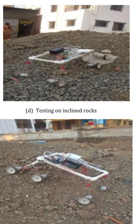
© 2018, IRJET | Impact Factor value: 6.171 | ISO 9001:2008 Certified Journal | Page 3512 (d) Testing on inclined rocks
(e) Testing on Small hilly structure of soil
TESTING OF ATV MODEL:-
While testing of our model first we kept on the end of rocky hill structure at a construction site and started test and the model successfully climbed the rocky hill as shown in fig.(a). Then we tested our model on inclined uneven surface as shown in fig.(b) and the model climbed easily. After that we kept our model on flat surface with obstacles as shown in fig.(c) and it easily passed over the obstacles.
We tested our model on inclined rocks as shown in fig.(e) where we came to know that we need more ground clearance to climb easily so we changed the wheels to grater size. After that we tasted our model on small hilly structure of soil as shown in fig.(e) where it climbs easily.
1. The design of model found safe and reliable for various working conditions.
2. All the parameters like Safety, Cost, Reliability, Performance, Durability, aesthetics, Standard dimensions & material are satisfactorily fulfilled.
3. The designed vehicle is able to stand against any road with any difficulty.
4. From Results we conclude that the design and manufactured model can climb the angle up to 60-70˚. During stair climbing test for 50mm and 70 mm wheel Diameter, It is possible to climb the stair at height of 15 % of height of the vehicle. At 70 degree inclination, vehicle is travel easily in forward and reverse conditions with carrying the load of its own.
FUTURE SCOPE
1) Transport of soldiers to places where trucks cannot go, with minimal engine noise as its run by electric motors.
2) Remote driven vehicle can be made using this vehicle structure that can help transport material to remote areas.
3) With the development in technology the rover can be used for investigation purpose with the cameras installed on the rover and minimizing the size of rover.
4) Can be modified to large scale for military use.
REFERENCES
1. P. Panigrahi, A. Barik, Rajneesh R. & R. K. Sahu, “Introduction of Mechanical Gear Type Steering Mechanism to Rocker Bogie”, Imperial Journal of Interdisciplinary Research (IJIR) Vol-2, Issue-5, ISSN: 2454-1362,2016.
[image:6.595.46.281.74.467.2]