2. School of Information Technology Engineering, Vellore
ABSTRACT
This paper proposes a modified form of the design for low dynamic power adder using a reset network in the CMOS dynamic logic family. The results show that the dynamic power reduces as compared to lower dynamic power logic and the domino logic. In this modified form of the low dynamic power adder, the logic outputs are reset to low during the pre-discharge phase which is the high input to the clock. The logic evaluation takes place when the clock input is low. The modified logic is better than domino logic since it does not require an inverter for cascading the gates. In Pre-discharging, resetting the output low prevents the problems of charge sharing and charge leakage associated with the other dynamic logic families and also it avoids the static power dissipation which exists in the low power dynamic logic. Also resetting the output low avoids the problem of high transition time from high level to low level which exists in circuits employing PMOS logic. The proposed circuit is a mix of PMOS logic and a dynamic logic. The proposed logic cell can be cascaded in a domino like fashion without the need of an inverter.
Keywords:
CMOS, VLSI, Combinational circuits1.
INTRODUCTION
The increasing demand for low power Very Large Scale Integration (VLSI) can be addressed at different design levels, such as the architecture, circuit, layout, and the process technology used [1]. At the circuit design level, considerable potential for power savings exists by means of proper choice of a logic style for implementing combinational circuits. This is because all the parameters governing power dissipation switching capacitance, transition activity, and short-circuit currents are strongly influenced by the chosen logic style. Depending upon the application, the kind of circuit to be implemented, and the design technique used, different performance aspects become important, disallowing the formation of universal rules for optimal logic styles.
In order to improve the area and speed of the recent CMOS logic styles, non-complementary circuit structures and dynamic circuit operations are used. Domino CMOS is widely used in high performance integrated circuits. It reduces the device count, silicon area and improves the performance as compared to the standard fully complementary static CMOS logic. Domino logic uses the dynamic concept in which the output is pre-charged to VDD in the pre-charging phase and conditionally discharges it during the evaluation phase.
However the major problem with domino is the charge redistribution and excessive power dissipation due to the switching activity and the clock load [4]
To deal with excessive power dissipation of the dynamic logic, the current design methodologies trade power for performance in the delay critical sections of the circuit [8-11]. Ref [8-9] used a mix of dynamic and static circuit styles. Dual power supply is used in [10] and dual Vt transistors are used in [11]. The adder design in [8] uses two dynamic gates between three gates. The design in [10] uses a low voltage supply for clocking the dynamic design and high supply voltage for the logic evaluation. Ref [11] uses dynamic logic for adder design with more than 80% of the device widths in the high speed core employ low Vt. Several lower power high performance structures are presented in [12]
To circumvent leakage problems various compensating mechanisms have been proposed. They include a metal-insulator capacitor [13], a trickle transistor [14] or a weak DMESFET and diode [15].
A new logic family is proposed in [2] which improves the performance of arithmetic circuits, as compared to dynamic domino CMOS circuits. The logic family works on domino concept for dynamic circuits, with the added feature that gates commence evaluation even before all their inputs are valid. This fact results in very fast evaluation in the computational block [2]. But the logic suffers with the problem of static power dissipation for certain input cases and this problem is addressed in this work. A modified design is proposed to prevent static power dissipation.
The modified design is simulated in TANNER S-SEDIT software and results are compared with the design proposed in low dynamic power adder. Inverters are simulated for the case of CMOS, domino, Low Dynamic Power Dynamic gate (LDPD) and Modified Low Dynamic Power (MLDP) logic. A 1 bit full adder is simulated for the LDPD logic and the modified logic results are tabulated. Layout of the adder is prepared in TANNER L-EDIT. The principle of operation of LDPD [2] design is illustrated in section 2. The modified design is described in section 3. The issues of cascading problems and static power dissipation are dealt in section 4.The 1-bit full adder design is demonstrated in section 5. The simulation result of 1-bit full adder is in section 6.
2.
THE
PREVIOUS
LDPD
DESIGN
Fig1 Basic structure of the previous proposed logic gate LDPD (Low dynamic power dynamic gate)
These transistors are paralleled together. This block is connected in series with another transistor which is activated only in reset phase. In the previous LDPD logic high clock input is the pre-discharge (reset) phase and low clock input is the evaluation phase. In the standard dynamic logic the output is always charged to VDD during pre-charge phase which causes the cascading problem, charge sharing problem and leakage current problem. Cascading of domino logic involves incorporation of inverters at the output logic block. This causes not only extra area but also, sufficient longer delays because of the inverters.
The drawback of LDPD is that during evaluation phase when all the inputs are high, direct path exists from VDD to GND which causes the static power dissipation. Thus during evaluation phase when output is low ratio logic is made. This problem is illustrated in Fig 2.
Fig 2. Static power dissipation in inverter LDPD.
Fig 3 Simulated result for inverter in LDPD logic
Fig: 4. Simulated result for inverter in domino logic
[image:2.595.304.552.71.228.2]
Fig 5. Simulated result for inverter in MLPD logic
[image:2.595.305.564.276.443.2]In Fig 3 till 100ns the clock as well as input is high and this resets the output to GND. When the clock gets low, the PMOS in the inverter gets on and the inverter is now in evaluation mode. Because input is high the NMOS network of inverter is also ON and the direct path exists between VDD and GND. This causes significant static power dissipation. The nominal high voltage of inverter in this logic is VDD since the pull down network is off when the output is high but the nominal low voltage is not 0V. This results in low noise margin and more static power dissipation.
Fig 4 shows the inverter in domino logic. In this logic when clock input is low, the output node is pre-charged and when the clock input is high evaluation takes place.
Fig 7 shows the inverter in modified low dynamic power logic, the output node is reset when the clock input is high and evaluation takes place when the clock input is low
[image:2.595.96.240.395.536.2] [image:2.595.54.291.568.747.2]
Fig 6. Cascaded inverters in LDPD.
3. MODIFIED LDP DESIGN
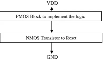
The basic structure of modified LDP design is shown in Fig 6. In the Modified Low Dynamic Power Design (MLDP) the output is pre-discharged to GND before evaluation as is done in [2] but the modified logic uses the PMOS network to implement the logic. Also no transistor is connected in series with the reset network. In general PMOS circuits are slow to transition from high to low. When transitioning from low to high, the transistors provide low resistance, and the capacitive charge at the output drains away very quickly. But the resistance between the output and the negative supply rail is much greater, so the high to low transition takes longer.
Modified LDP design uses the dynamic concept that the output node is made low during the reset phase and it gets conditionally charged to VDD through the PMOS network in the evaluation phase PMOS network is used only for low to high transition in the modified logic and this reduces the transition time for low to high. The high to low transition is done through NMOS network, thus well know problems of low to high transition and static power dissipation in case of PMOS logic is avoided in the modified LDP design.
VDD
[image:3.595.305.557.315.479.2]GND
Fig 7. Basic structure of MLDP (Modified Low Dynamic Power)
Fig 8 shows a simple inverter in modified LDP design. In MLPD the reset network is off during the evaluation phase hence no direct path exist path exists between the VDD and GND .This avoids the ratio logic used in LDPD and the noise margin of the modified logic is more, since the output is pre-discharged to GND during reset phase the need for inverters to restore the output node is eliminated. This also eliminates the problem of charge redistribution and leakage current. Restoring networks have been required in all other published works on domino logic
Fig 8.. Inverter in MLPD
Fig 9. Cascaded inverter in MLDP
4. 1-BIT FULL ADDER DESIGN IN
MODIFIED LOGIC
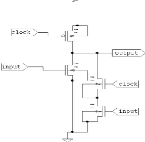
In this section 1-bit full adder design in the modified logic is discussed. The structure of the basic sum and carry cell used is same as the CMOS adder cell used in [3]. The schematic of 1 bit full adder is shown in fig 10. The software used for schematic simulation is S-Edit from Tanner. During the evaluation phase the sum bar will certainly be high if any two of the three inputs ci, a, b are high and the other input is low. In this case the carrybar will be low, and the sumbar will get charged through PMOS network. If all the three inputs ci, a, b are high then sumbar will be zero and in this case the carrybar will be low. In case all inputs a, b and carry in (ci) are all low both sumbar and carrybar will be high. In other cases the carry bar will be high and the sumbar will remain low. The sumbar is low already. It will be asserted high only by inputs during evaluation phase.. The reset output makes the fall time low and the use of PMOS network for low to high transition makes the rise time low thereby improving the overall performance. The layout of the carrybar logic and sumbar logic is created separately in L-EDIT software. The layout for sumbar is shown in Fig 12 and the layout for carrybar is shown in fig 13. The simulated waveform for schematic of carrybar is shown in fig 11.
PMOS Block to implement the logic
[image:3.595.63.259.516.635.2]Fig .10 Schematic of Full Adder in MLDP Logic
5. SIMULATION RESULTS
We have used tanner S-Edit software for simulation. The technology used is 180nm and the supply voltage used is 5V. The average power dissipation of 1 bit full adder in case of LDPD is 1.7 times more than the power dissipation of 1 bit adder in MLDP. Thus MLDP is better than LDPD in terms of average power consumption. Also inverter is simulated in domino, LDPD and MLDP logic. It is found that average power consumed in MLDP is 1.3 times lower than that in domino logic and both the logic are more than 5 fold better than LDPD logic.
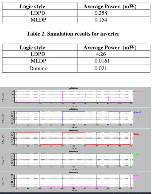
Table 1. Simulation Results for 1 Bit Full Adder
Logic style Average Power (mW)
[image:4.595.76.294.73.260.2]LDPD 0.258 MLDP 0.154
Table 2. Simulation results for inverter
Logic style Average Power (mW)
LDPD 4.26 MLDP 0.0161 Domino 0.021
Fig. 11 Simulated waveform for carry in MLDP
Fig 12 Layout of sum bar
Fig 13. Layout of carrybar
6. CONCLUSION
[image:4.595.55.300.420.734.2]for low to high transition increases the overall performance. The reset of gate output to low during the reset phase completely removes the problem of charge redistribution and leakage current which is found in all the existing domino logics. Also the proposed logic does not need restoring inverters when gates are cascaded thereby saving some area and reducing propagation delay, in comparison with other domino logic families.
7. REFERENCES
[1] J.M. Rabey, A Chandrakasan, B. Nikolic, Digital Integrated circuits. A Design perspective-2c Prentice –Hal, Upper Saddle River , NI,2002.
[2] M . Nadi Senejani, M. Hossein Ghadiry, Low Dyanmic Power
High Performance Adder.
CADSM,24-28February,2009,Polyana-svalyava(Zakarpattaya),Ukraine.
[3] C. Fang, C. Haung, J. Wamg , C. Yeh, Fast and Compact Dynamic Ripple Carry Adder Design, proceedings of IEEE Asia Pecific Conference on ASIC, APASIC 2002, August 2002, Taipei,Taiwan
[4] R.Zimmermann, W.Fiehtner, Low Power logic styles: CMOS versus Pass-transisitor logic,IEEE J. Solid-State circuits 32(7)(1997)1079-1090
[5] N.Weste K. Eshraghian, Principles of CMOS VLSI Design. A system perspective , Addison Weslay, M.A,1998
[6] Y.Jiang, A. Al-sheridah, Y.Wang, E.Sha, J. Chung . A novel multiplexer based low power full adder, IEEE Trans. Circuits Systems II 52(7) (2004) 345-348
[7] A. P. Chandrakasan and R.W. Brodersen, Low Power Digital CMOS Design, Norwell, MA: Kluwer, 1995
[8] S. Mathew, M. Anders, R. Krishnamurthy, S.Borkar, A 4 GHz 130nm address generation unit with 32-bit sparse-tree adder core, Proceedings of IEEE VLSI Circuits Symposium , Honululu, June 2002, pp-126-127.
[9] S. Mathew, M. Anders, R. Krishnamurthy, S.Borkar, A 4 GHz 130nm address generation unit with 32-bit sparse-tree adder core, IEEE J. Solid State Circuits 38(5) (2003) 689-695.
2003, pp 334-335.
[12] Victor Navarro-Botello, Juan A. Motiel-Nelson, Saeid Nooshabadi, “High Performance low power CMOS dynamic for arithmetic circuits”, Microelctronics Journal 38,(2007) 482-488
[13] D. H. K. Hoe and A. T. Salama “Dynamic GaAs capacitively coupled domino logic (CCDL),” IEEE J. Solid State Circuits, Vol 26, pp 844-849, June 1991.
[14] O. M. K. Law and C. A. T. Salama, “GaAs split phase dynamic logic,” IEEE J. Solid State Circuits, Vol 29, pp. 617-622, May 1994
[15] V Chandramouli, N. Michell, and K. F. Smith, “ A new, precharged, low power logic family for GaAs circuits,” IEEE J. Solid-State Circuits, vol. 30, pp. 140-143, Feb 1995.
AUTHORS PROFILE
R.Sakthivel received Bachelor degree in Electrical Engineering
from Madras University in 2000 and the M.E degree in Applied Electronics from Anna University in 2004. He is working as an Assistant Professor (Senior) and division Leader of VLSI Division in the School of Electronics Engineering at Vellore Institute of Technology University, Vellore. His current research includes Low power VLSI Design, Developing High speed architecture for cryptography, Analog VLSI. He is a member IEEE, ISTE, SSI and VLSI Society of India (VSI). He is the Co-author of Basic Electrical Engineering" Published by Sonaversity in the year 2001 and author of VLSI Design published by S.Chand in the year 2007. He has also published several technical papers in national and international conferences and Journals.
M.Vanitha received M.Tech from VIT University and MCA