Enhancing Channel Coding using AES Block Cipher
Eman Mohammed
Mahmoud
Communications Engineering Department
Modern Academy of Engineering and
Technology Cairo, Egypt
Abdelhalim Zekry
Communications Engineering Department
Faculty of Engineering Ain shams University
Cairo, Egypt
Ahmed Abd El Hafez
Communications Engineering Department
MTC Cairo, Egypt
Talaat A. Elgarf
Communications Engineering Department
Higher Technological Institute Cairo, Egypt
ABSTRACT
A key benefit of channel coding is the ability to protect data against channel impairments. Essentially, the channel coder adds redundancy bits that provide a way to correct corrupted data. Encryption is another way of protecting data against channel impairments and unintended interception or forging.
This paper introduces an efficient approach of increasing coding gain at the receiver end. The implemented approach uses the advanced encryption standard (AES) cryptographic algorithm as a primary part of channel coding process. The simulation result of this implemented approach is evaluated in the presence of additive white Gaussian noise (AWGN).
General Terms
Communication system, channel coder, Algorithm.
Key words
channel coding, Maximum A Posteriori Probability (MAP) algorithm, soft input soft output channel decoder (SISO), advanced encryption standard (AES), Joint Channel Coding and Cryptography, soft input decryption (SID), soft input encryption (SIE).
1.
INTRODUCTION
Channel coding uses certain mechanisms to create redundancy bits within the transmitted data to reduce errors during transmission. This process is of significant importance within the communication industry. This technique is used commonly in wireless communications networks, especially within mobile communication systems which are mostly vulnerable to factors like exceeding data traffic, maximum transmission interferences, and significant data-loss due to channel noise[1]. On the other hand Cryptography is primarily used for secure communications. The main goal of modern cryptography is normally considered as data confidentiality, data authentication and user authentication [2].
Joint Channel Coding and Cryptography is a new approach used to improve channel coding gain by developing cooperation between the soft channel coding techniques and the cryptography algorithms[3], [4]. In this paper a new channel coding method is implemented based on the Joint Channel Coding and Cryptography approach. Soft input encryption (SIE) and soft output decryption (SID) mechanisms are designed and implemented to improve channel coding gain. The results are calculated in terms of bit error rate (BER), simulation time and complexity.
The rest of the paper is organized as follows. In section 2, a digital error correction system based on soft decoding
algorithm is introduced. In section 3, the proposed error correction system is described. The system model is presented in section 4. The results are presented and discussed in section 5. Finally, the conclusion is given in Section 6.
2.
RELATED ERROR CORRECTION
SYSTEM WITH SISO DECODER
The implemented error correction system with iterative decoding algorithm is concerned with channel encoder, BPSK modulator, AWGN and iterative decoding Algorithm.
2.1
Channel Encoder
Convolution encoder and turbo encoder are implemented in this paper as two types of channel encoders. Convolutional codes are commonly used in modern telecommunications as an effective tool for securing reliable data transmission over noisy channels [5].The used convolution encoder is a recursive systematic convolution (RSC) one.
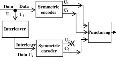
[image:1.595.328.531.577.684.2]Turbo codes are widely recognized as a very efficient means for high-quality communications especially at low SNR per data bit. Turbo encoder is composed of two recursive systematic convolutional (RSC) encoders, as shown in Fig 1. The input information sequence is encoded twice by the two RSC encoders. The first encoder processes the information in its original order, while the second encoder processes the same sequence in a different order obtained by an interleaver [6]. Then the encoded data is applied to the Puncturing device, which controls the output bit rate. Puncturing device is used to drop some output bits. The resulting code has higher rate but lower correcting capability.
Fig 1: Turbo encoder structure Data
U1
U1
C1
U2
C2
X
Interleave
Data U2
Symmetric encoder
Symmetric encoder Interleaver
Data
U1
2.2
BPSK Modulation and AWGN
Channel
The encoded data is applied to BPSK modulation which maps the bit 0 into the signal “+1”, while the signal “-1” is sent for a binary value 1.
The implemented AWGN model has variance and zero mean value, where N0 is the single-sided noise power
spectrum density. The N0 relation is as follow ,
where Ec is energy per bit of the coded bits, α is the desired
signal to noise ratio ( ) and R is a code rate of the convolutional encoder.
2.3
Soft Decode Algorithm
The soft-in, soft-out (SISO) decoding is used as soft decode algorithm. The SISO decoder receives a soft real value of the signal as input. The decoder then deduces an estimation for each data bit expressing the probability of the transmitted data bit. This probability is the soft output. The sign of soft output is a hard decision (H), and the magnitude is used as reliability value of a hard decision (L_value). Higher L_value means more reliable hard decision information. Lower L_value means less reliable decision information. When the L_value is equal to 0, the probability of the correctness of the decision is 0.5. The SISO decoding minimizes the average decoded symbol error rate. The SISO implements operations related to the maximum a posteriori (MAP) algorithm. The decoder is executed using a version of the classic MAP algorithm implemented in the log-domain [7], [8].
The log-MAP algorithm gives good results for low S/N ratio. The log MAP algorithm finds the most probable information bit that was transmitted. That means the log MAP algorithm minimizes the bit or symbol error probability.
3.
THE PROPOSED CHANNEL
CODING SYSTEM
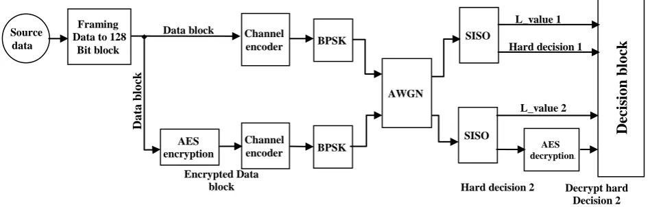
Fig 2 represents the communication system with the new implemented channel coding technique. First of all, the bit steam must be framed into 128 bit blocks to follow the AES needs. These blocks are sent into two different paths. The data blocks of the first path are applied to channel encoder and BPSK modulation. The data blocks of the second path are firstly encrypted with AES encryption algorithm then applied to the channel encoder and BPSK modulator. The output of the two paths may be multiplexed and then applied to an AWGN channel. In this case AES algorithm is used for channel coding purpose only. On the other hand to insure security purpose, the output of the two paths may be applied directly to two different AWGN channel. The first path must be transmitted in secure Channel to protect data frames against cryptanalysis. While the second path can be transmit over unsecure channel. The overall rate of the implemented algorithm is twice of the channel encoder rate. At receiver, the SISO receives data blocks of each path. This decoder used to decode data blocks. The output of this decoder is the L_value which used to improve channel coding gain. Hard decision (H) is another output produced from SISO decoder, which is the corresponding bit stream of the reliability value. The outputs of the SISO decoder is applied to the decision block except the second path hard decision, it is sent to AES decryption before applied to the decision block. The decision block is responsible for improving channel coding performance [9], [10].
[image:2.595.61.545.460.611.2]The proposed communication system is thus based on AES block cipher, channel encoder, binary phase shift keying (BPSK), AWGN channel and SISO decoder and the decision block.
Fig 2: The proposed channel coding system
3.1
AES Block Cipher
The advanced encryption standard (AES) algorithm is a symmetric block cipher that can process data blocks of 128 bits using cryptographic keys of 128, 192 and 256 bits. It is a Substitution-Permutation Network designed with a single collection of steps called a round that are repeated 9, 11, or 13 times depending on the key length to map plaintext to ciphertext [11] ,[12].
Each processing round involves four steps: 1. Substitute bytes – Uses an S-box to perform a byte by byte substitution of the block, 2. Shift rows – A simple permutation, 3. Mix column –
A substitution method where data in each column from the shift row step is multiplied by the algorithm’s matrix and 4. Add round key – The key for the processing round is XORed with the data [13].
The length of the secret key is selected to be 128 bit. This selection reduces the processing time and the system complexity [14]. As AES is used for error correction purpose instead of ciphering, the key size is not important.
AES exhibits a very effective cryptographic property called the avalanche effect. Essentially, this means that for each bit change in plaintext, the cryptographic algorithm produces changes in more than one-half of all the ciphertext bits as seen Encrypted Data
block
L_value 1 Source
data
Framing Data to 128
Bit block
Channel encoder
Channel
encoder BPSK AES
encryption
SISO SISO
D
ec
is
ion b
lock
AES decryption..
Data block
Hard decision 1
Hard decision 2 L_value 2
Decrypt hard Decision 2
Da
ta
b
lo
ck
in fig 3[15]. This property is used to improve the error correction probability.
Fig 3: The Avalanche effect of AES cipher
3.2
The Decision block
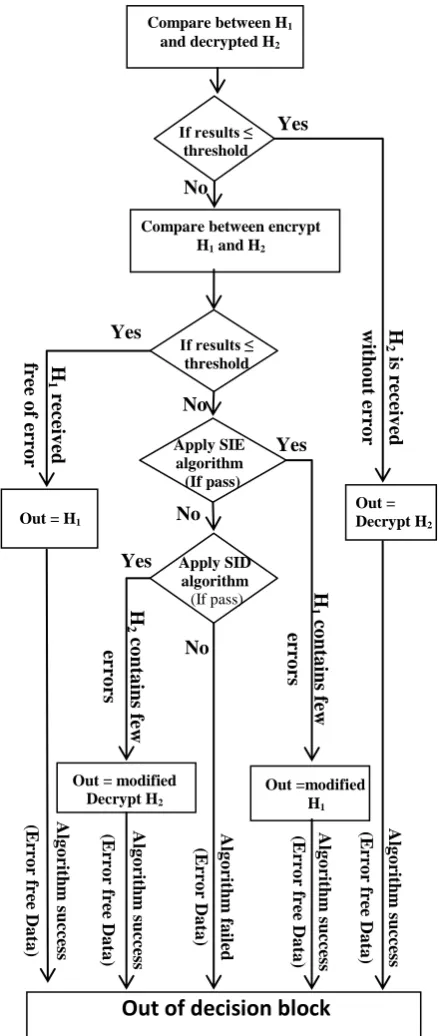
This block is responsible for improving channel coding gain. Fig 4 represents the flowchart of the implemented decision block. This block has four inputs, the hard decision bit stream of unencrypted path 1 and its corresponding reliability value which are denoted by H1 and L_value_1 respectively and the
hard decision bit stream of encrypted path 2 and its corresponding reliability value which are denoted by H2 and
L_value_2 respectively. The basic idea of this block is to compare between H1 and decrypt H2 (d_H2) to check if this
difference is below threshold value [16]. The threshold value is the maximum expected number of errors due to SNR limited by the avalanche effect value.
Fig 4: Flowchart of the Decision Block
This comparison has the following possibilities:
1) Both streams are error free.
2) The decrypt stream ‘H2’ is error free whereas the
stream ‘H1’ has few bit error.
3) The ‘H1’ stream applied to decision block is error
free whereas the decrypt stream ‘H2’ applied to
decision block has about 50% errors in case of avalanche effect.
4) Both streams have errors. If results ≤ threshold Compare between H1
and decrypted H2
Yes
H
2 is
re
ce
iv
ed
wit
ho
ut
er
ro
r
Out = Decrypt H2
Compare between encrypt H1 and H2
If results ≤ threshold
H
1
re
ce
iv
ed
fre
e
o
f er
ro
r
Yes
Apply SIE algorithm (If pass)
Out =modified H1
H
1
co
nta
ins
f
ew
er
ro
rs
Yes
If
p
as
s
Out = modified Decrypt H2
H
2 co
nta
ins
f
ew
er
ro
rs
Yes
Out of decision block
Alg
o
rith
m
succ
ess
(Er
ro
r
fr
ee
Da
ta
)
Alg
o
rith
m
succ
ess
(Er
ro
r
fr
ee
Da
ta
)
Alg
o
rith
m
succ
ess
(Er
ro
r
fr
ee
Da
ta
)
Alg
o
rith
m
fa
il
ed
(Er
ro
r
Da
ta
)
Alg
o
rith
m
succ
ess
(Er
ro
r
fr
ee
Da
ta
)
No
No
No No
Apply SID algorithm
[image:3.595.56.279.92.228.2]4.
SYSTEM MODEL
The applied data of length 1280000 is framed to 10000 frames. These data frames are fed directly to the selected encoder. Also these data frames are applied to AES cipher and then applied to the encoder. A convolutional and a turbo coder are used in the simulations. The used convolution encoder has a code rate and a constraint length . The turbo encoder with is based on two parallel RSC convolutional encoders with rate and Puncturing block which used to increase turbo encoder rate from
to . The effective coding rate of our implemented
system is equal to twice the coding rate. The encoded frames are then modulated and transmitted over an AWGN channel. The received frames are applied to SISO decoder which is responsible for producing reliability value (L_value) and hard decision H for each path. The turbo decoder performs one and two iterations. The hard decision of path 2, the encrypted path, H2 is applied to AES decipher in order to match original data.
The hard decision H1 and its reliability value L_value_1 of
unencrypted path and the decrypted hard decision d_H2 and
H2 reliability value L_value_2 of encrypted path are then
applied to decision block.
4.1
The Implemented Mechanism to
Improve Channel Coding Gain
(decision block)
The decision block compares between H1 and d_H2. If two
data frames are identical (the two frames are error free), the out is H1. Else if the compared value is below the threshold
this mean that H2 is received error free and the output is d_H2.
If the compared value is greater than the threshold, the decision block checks if H1 is received error free or not. In
order to do that H1 is encrypted and a comparison is done
between E_H1 and H2. If the compared value is below the
threshold, the output is H1 free of error. Else H1 and H2 are
received with error; the decision block applies soft input encryption SIE mechanism. This mechanism gives pass=1 when the modified H1 is error free, if not (pass=0) SID
mechanism is applied. If this mechanism gives pass=1 then modified d_H2 is the output. Else the output will be H1, but it
contains errors and the mechanism gives pass=0 [17].
4.2
Soft Input Encryption
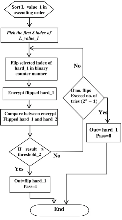
Fig 5 represents the soft input encryption SIE flowchart. As noted below, High absolute L-values mean a high probability of bit correctness. L-values are used for finding incorrectly received bits. H1, H2 and L_value_1 are applied to SIE block.
First of all, the L_value_1 is sorted. Then the 8 bits with the lowest L_value of H1 are selected. These bits give only an
orientation which bits may be wrong decoded. The selection of eight bits means that SIE will have 255 attempts (28 −1) to do error correction. In each attempt, a bit or combinations of bits are inverted (0 to 1 or 1 to 0) and then encryption is performed. For illustration, only a bit with the lowest L_value is flipped, then only a bit of the second lowest magnitude L_value is flipped, after that first two bits with the lowest magnitude soft values are flipped and so on till the last bit flipping combination.
In each attempt, the encrypted modified H1 is compared with
H2 and the results are compared with the threshold. If the
threshold is greater than the compared value, the modified H1
is selected to be the output of SIE. This output is exactly
[image:4.595.320.533.102.486.2]matches the original data. SIE successes in correcting all errors contained in H1. Else another attempt will take place.
Fig 5: The Soft Input Encryption flowchart
4.1
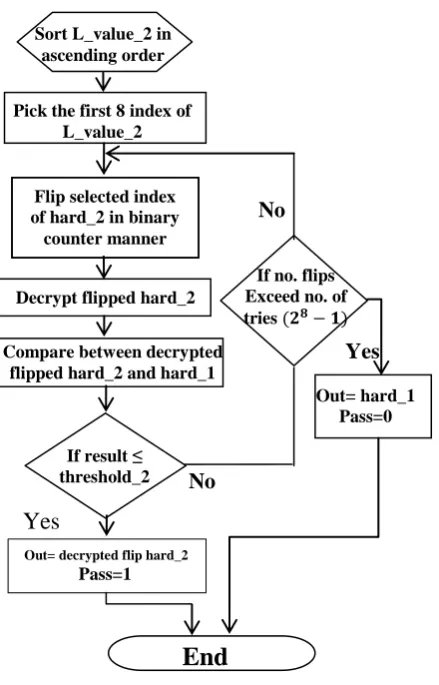
Soft output Decryption
Fig 6 represents the soft input decryption SID flowchart. First of all, the L_value_2 is sorted. Then the 8 bits with the lowest L_values of H2 are selected. In each attempt, a bit or
combinations of bits are inverted (0 to 1 or 1 to 0) and then decryption is performed. The decrypted modified H2 is
compared with H1 and the results are compared with the
threshold. If the threshold is greater than the compared value, the decrypt modified H2 is selected to be the output of SID
[18]. This output is exactly matches the original data. SID successes in correcting all errors contained in H2. Else another
attempt will take place. Compare between encrypt Flipped hard_1 and hard_2
Sort L_value_1 in ascending order
Pick the first 8 index of L_value_1
Flip selected index of hard_1 in binary
counter manner
Encrypt flipped hard_1
If result ≤ threshold_2
If no. flips Exceed no. of tries
No
No
Out=flip hard_1 Pass=1 Yes
Out= hard_1 Pass=0
Yes
End
Fig 6: The Soft Input Decryption flowchart
5.
RESULTS AND DISCUSSIONS
The proposed system is implemented in Matlab. The simulation results are obtained for the conventional channel coding system with the same overall coding rate of 1/4 and our channel coding system with AES.
[image:5.595.318.541.221.409.2]The proposed system shown in Fig 2 has an overall rate of 1/4 because both of the convolutional encoders used in this system are of rate 1/2. This system is then compared with the related error correction system shown in Figure 1 having a convolutional encoder of rate 1/4. Fig 7 represents that the implemented system using cryptography exhibits considerable coding gain of 2.48 dB over the related system without cryptography. The reference point for this coding gain is at bit error rate of 10-3.Furthermore, it can be observed that the proposed system achieves better performance of about 3.5 dB.
Fig 7: BER versus Eb / N0 for ordinary and implemented
systems with convolution coder
Fig 8 represents the corresponding bit error rate (BER) as a function of Eb/N0 for the proposed system with two turbo
encoders having an effective coding rate of 1/4. As a reference, we also plot the performance of related system using rate 1/2 turbo encoder. Fig 8 clearly shows that the error correction capability of proposed system is superior to that of the conventional turbo encoder. The proposed system which performs 1iteration shows a coding gain of about 1.27 dB at BER 10-3 relative to the ordinary turbo coder performing 1 iteration at decoder. Furthermore, the proposed system with 2 iterations shows a coding gain of about 0.97 dB at BER 10-3 relative to the ordinary turbo coder performing 2 iterations at the decoder.
Fig 8: BER versus Eb/ N0 for ordinary and implemented
systems with turbo coder
In fig 9 a comparison has been done between the proposed system using convolution coder and the proposed system using turbo coder performing one and two iterations at decoder. The simulation of proposed system using convolutional coder are faster than the proposed system using turbo coder performing two iterations at decoder ( as seen in table 1) and the coding gain of this turbo coder is quite similar to that of convolution coder (coding gain = 0.37 dB at BER 10-3 ). The simulation of proposed system using convolutional coder are slower than the proposed system using turbo coder performing one iteration at decoder ( as seen in table 1) if Eb/N0=1:2 dB and the coding gain of convolutional coder is
quite similar to that of the turbo coder (coding gain = 0.2 dB at BER 10-2 ). However, at higher E
b/N0 the proposed system
[image:5.595.57.282.605.741.2]using convolutional coder are faster than this turbo coder. The proposed system using convolution coders are less complex than the proposed system using turbo coders.
Table 1 Average simulation time of one frame with respect to SNR and coding type
SNR in dB
1dB 2 dB 3 dB 4 dB 5 dB
Convolutional coder
0.2032 sec
0.1519 sec
0.061 sec
0.059 sec
0.059 sec
Turbo coder with 1 iteration at
decoder
0.10311 sec
0.3173 sec
0.1127 sec
0.1069 sec
0.1071 sec
Turbo coder with 2 iteration at
decoder
0.5670 sec
0.2167 sec
0.1981 sec
0.1986 sec
0.1945 sec
Compare between decrypted flipped hard_2 and hard_1
Sort L_value_2 in ascending order
Pick the first 8 index of L_value_2
Flip selected index of hard_2 in binary counter manner
Decrypt flipped hard_2
If result ≤ threshold_2
If no. flips Exceed no. of tries
No
No
Out= decrypted flip hard_2
Pass=1
Yes
Out= hard_1 Pass=0
Yes
[image:5.595.312.548.645.767.2]Fig 9: BER versus Eb / N0 for the implemented systems
6.
CONCLUSION
In this paper, a new channel coding system is proposed, which uses soft outputs of MAP decoder and Avalanche Effect of AES block cipher. The simulation results show that better performance in channel coding can be achieved if SIE and SID are used as a decoding correction mechanism. The proposed channel coding mechanism is compared with the original channel coding systems, which uses convolutional encoder and turbo encoder of the same coding rate.
For lower Eb/N0, the proposed system using turbo coder’s
with 2 iterations at decoder is better than the proposed system using convolutional coders in terms of BER and simulation time. However for higher Eb/N0, the proposed system using
convolution coders becomes better than others due to lower simulation time and quite similar coding gain.
7.
REFERENCES
[1] Abdullah, Saifuddin. "Channel Coding Techniques in Mobile Communication Systems". n.d.
http://www.ehow.com/info_8633062_channel-
techniques-mobile-communication-systems.html#ixzz27VRPUK2t (accessed 5 25, 2012).
1.
[2] Boudriga, Noureddine. "SECURITY of mobile communications". Taylor and Francis Group, LLC, 2010.
[3] Natase Zivic . "Probability of Collisions in Soft Input Decryption." American Conference On Applied Mathematics (Math '08). Harvard, Massachusetts, USA, 2008.
[4] Natasa Zivic and Christoph Ruland. "Parallel Joint Channel Coding and Cryptography". World Academy of Science, Engineering and Technology (WASET.ORG World Academy of Science, Engineering and Technology) 31, no. 41 (July 2008): 536 -539.
[5] Korhonen, Juha. "Introduction to 3G Mobile Communications". second. Boston • London: Artech House mobile communications series, 2003.
[6] Ipatov, Valery P. "Spread Spectrum and CDMA
Principles and Applications". England: John Wiley & Sons Ltd, The Atrium, Southern Gate, Chichester,, 2005.
[7] Pless, W. Cary Huffman and Vera. "Foundamentals of Error- Correcting Codes". frist. United Kingdom: Cambridge University Press, 2003.
[8] Borda, Monica. "Fundamentals in Information Theory and Coding". Romania: Springer-Verlag Berlin Heidelberg, 2011.
[9] Ayyaz Mahmood. "Method to Improve Channel Coding Using Cryptography." World Academy of Science, Engineering and Technology, 2008: 525-528.
[10] Natasa ZIVIC, Obaid Ur Rehman and Christoph Ruland. "Analysis of serial and parallel soft input decryption schemes over a wireless channel." Performance Evaluation of Computer & Telecommunication Systems. SPECTS 2009, 2009. 282 - 288 .
[11] Rhee, Man Young. "Internet Security Cryptographic Principles, Algorithms and Protocols". England: John Wiley & Sons Ltd, The Atrium, Southern Gate, Chichester,West Sussex PO19 8SQ, 2003.
[12] Welschenbach and Michael. "Cryptography in C and C++". second . GraceWong,Michael Welschenbach, 2005.
[13] Joan Daernen, Vincent Rijrnen. "The Design of Rijndael {AES - The Advanced Encryption Standard}". Verlag Berlin Heidelberg: Springer-, 2002.
[14] Denis, Tom St. "Cryptography for Developers". Rockland: Syngress Publishing, Inc., 2007.
[15] Stallings, William. "Cryptography and Network Security Principles and Practices". Prentice Hall, 2006.
[16] Natasa Zivic, "Increasing of coding gain of Soft Input Soft Output channel decoding" Electrotechnical Conference (MELECON), 16th. IEEE Mediterranean, 2012. 1001 - 1004.
[17] Natasa Zivic and Christoph Ruland, "Channel Coding as a Cryptography Enhancer" WSEAS Transactions on Communications, WSEAS - World Scientific and Engineering Academy and Society, 2008. 83-91.