Journal of Chemical and Pharmaceutical Research, 2014, 6(1):97-103
Research Article
CODEN(USA) : JCPRC5
ISSN : 0975-7384
Camera calibration optimization technique based on genetic algorithms
Changying Liu
1, Yanmei Jia
1, Wenjing Cai
1, Tianhao Wang
2*, Yuhe Song
1, Xiaowen Sun
1and Jundong Zhang
21College of Instrumentation and Electrical Engineering, Jilin University, Changchun, Jilin, China 2The State Key Laboratory of Automobile Simulation and Control, Jilin University, Changchun, Jilin, China
_____________________________________________________________________________________________
ABSTRACT
Vision measurement technology is technology that gets information about measured object being imagined. Therefore, measurement accuracy is directly related to camera parameter calibration accuracy. As for the camera parameter calibration problem, this paper proposes a camera parameter calibration method based on genetic optimization algorithm. A more comprehensive camera imaging model can be built through the ideal pinhole model radial distortion, tangential distortion and distortion correction affine and non-orthogonal; A more comprehensive camera imaging model can be built through the ideal pinhole model radial distortion, tangential distortion and distortion correction affine and non-orthogonal; Using high-precision coordinate measuring machine and the luminous intensity adjustable infrared diode component to build a virtual three-dimensional calibration template provides high-precision calibration space calibration point of calibration . We can derivate reversely calibrated control points by calibration parameter to obtain regularized stereo calibration error 1.082 and Standard deviation of the thrust reverser 0.016. So the calibration method proposed in this paper is feasible and has good calibration accuracy.
Key words: Vision measurement Camera calibration Distortion correction Genetic algorithm
_____________________________________________________________________________________________
INTRODUCTION
Vision measurement technology is a new measurement technology and a breakthrough of measurement concept. It will extend measure technology to bionic technology field[1].It also adapts to higher requirements of measurement technology in measuring precision, measurement range and measurement conditions with a new measuring way of thinking. The measured information is obtained by a CCD camera in visual measurement technique. Therefore, the CCD camera is one of the key components of vision measurement system and system performance depends on the calibration accuracy of CCD camera parameter[2,3]. In order to improve the performance of visual measuring system and reduce the CCD camera parameters’ influence to overall performance to minimum, the CCD camera must be accurate[4,5]. The CCD camera parameter calibration algorithm based on. a genetic optimization algorithm has been proposed after researching the existing of camera parameter calibration algorithm and the characteristics of the camera model.
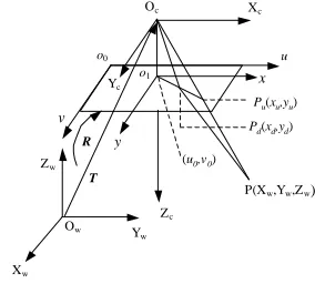
In order to describe the camera imaging process though camera parameters, the world coordinate system(space coordinate system),the camera coordinate system, pixel image coordinate system, the actual image coordinate system are necessary to be builted. The world coordinate system OwXwYwZw define a three dimensional space of a common coordinate system, according to the practical need to determine the coordinate system origin position and direction. The camera perspective projection center C is as to origin Oc of the camera coordinate system OcXcYcZc, axes Zc is perpendicular to the image plane of the camera; axes Xc and axes Yc parallel to the horizontal axis and vertical axis of the pixel units correspondingly. The origin o0 of pixels image coordinate system o0uv is created on image plane in the upper left corner, axes u and v parallel to the horizontal axis and vertical axis of the pixel units corresponding. The origin o1 of actual image coordinate system o1xy is built on the node of the optical axis of the camera and the image plane of the camera, axes x and y is to the parallel to the horizontal axis and vertical axis respectively. The method of establishing the coordinate system is shown as Figure 1.
Camera parameters describe the relative position and direction between the world coordinate system and the camera coordinate system. Through a 3×3 rotation matrix R and a 3×1 translation vector T to describe. In order to set up the link between any Pwi in world coordinates and any pi images coordinates. It needs to change the space coordinates transformation Pwi to the camera coordinate Pci, transformation process can be expressed as
Xc=RXw+T (1)
Where
X
c=
(
X
c,
Y
c,
Z
c)
T;X
w=
(
X
w,
Y
w,
Z
w)
T;T
=
(
t
x,
t
y,
t
z)
T;11 12 13 21 22 23 31 32 33
R
r r r
r r r
r r r
=
; rotation matrix R is
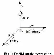
the unit matrix, it can express through the rotation Angle of passing around the Xc, Yc, Zc axis (Euler angle),ω,φ,κ can be expressed as (figure 2).
Xw Yw Zw Ow Xc Yc Zc x y Oc u v
(u0,v0)
o1 o0
P(Xw,Yw,Zw) Pu(xu,yu)
Pd(xd,yd)
[image:2.595.242.384.383.511.2]T R
Fig. 1 Coordinate system transformation
11 12 13 21 22 23 31 32 33 cos cos
cos sin sin sin cos sin sin cos sin cos
sin cos
cos cos sin sin sin cos sin sin sin cos sin cos sin cos cos r r r r r r r r r κ ϕ
κ ϕ ω κ ω
κ ω κ ϕ ω
κ ϕ
κ ω κ ϕ ω
κ ω κ ϕ ω
Fig. 2 Euclid angle expression
According to formula (1) and (2), the calibration parametersω,φ,κ can be determined to be
( )
32 33 31
21 11
arctan
arcsin
arctan
r r r
r r
ω
ϕ
κ
= −
=
= −
(3)
The camera's internal geometry and optical properties of the lens can be described by camera internal parameters. Camera internal parameters mainly include the effective focal length f and the image plane coordinates of the center (u0,v0). In the actual imaging system, a deviation of projection point offsetting the projection center will be occurred unavoidably because of the machining ad assembly errors of the lens and the CCD camera, and the introducing errors in the image acquisition process. Therefore, the ideal pinhole model can not meet the requirements and a more perfect camera imaging model must be adopted. On the basis of the pinhole imaging model, camera imaging model can be built after correcting the various distortion factors in the process of camera imaging, to calibrate camera parameters more precisely.
According to the characteristics of camera ideal pinhole imaging model, the correspondence between space coordinates of point Pci(Xci,Yci,Zci)and ideal perspective projection on the image plane coordinates pi(x’i,y’i)can be expressed as
i ci
i ci ci
x f X y Z Y
′
=
′
(4)
Because of the digital image acquired by camera in the form of a two dimensional array is stored in the computer and the image plane position (ui,vi)of each pixel in the image coordinates is the pixel’s rows and columns in the array, So there is not physical units showing the positions of the pixels in the image. Set dxand dyas a single physical
size pixel in the x axis and yaxis direction, then the transformation relation between Pixel Coordinates (ui,vi) of any pixel in the image pixels o1xy and coordinate system (xi,yi)in the actual image o1xy is as following:
(
)
(
00)
x i
i
y i
i
d u u x
d v v y
−
=
−
(5)
Pinhole model is only an approximation model of camera imaging process. As the existence of various distortion factors in the process of actual imaging, the image by space coordinates points is not on the pinhole model ideal position(x’i,y
’
Radial distortion(δxiRLD,δyiRLD) primarily is caused by a large off-axis angle and the manufacturing defects of lens, generated the optical center in the radial direction and gradually increases, can be approximately expressed as
(
)
(
)
2 4 6
1 2 3
2 4 6
1 2 3
i i i i
iRLD
iRLD i i i i
x k r k r k r x
y y k r k r k r
δ δ
+ +
=
+ +
(7)
Where ri=(xi2+yi2)1/2——the distance between the image points (xi,yi) and the camera optical axis;
k1,k2,k3 ——Correction factor for the radial distortion
Tangential distortion (δxiRLD,δyiRLD)mainly is caused by the curvature of the lens center is not strictly collinear, can be approximately expressed as
(
)
(
)
2 2
1 2
2 2
1 2
2 2
2 2
i i i i
iTLD
iTLD i i i i
p r x p x y x
y p x y p r y
δ δ
+ +
=
+ +
(8)
Where p1,p2 ——the tangential distortion correction coefficient
Affine and non-orthogonal distortion(δxiRLD,δyiRLD) is mainly caused by horizontal and vertical pixel size of inconsistency and scanning image acquisition card arranged in error and the non pixel vertical line the distortion can be approximated as
1 2 1
iAND i i
iAND i
x b x b y
y b y
δ δ
− +
=
(9)
Where b1,b2 ——Affine and non- orthogonal distortion correction coefficient
In summary, within the parameters of CCD camera: effective focal length f, the center coordinates (u0,ν0) of the image plane, radial distortion correction coefficient (k1,k2,k3), the tangential distortion correction coefficient (p1,p2), distortion and non-orthogonal affine distortion correction coefficient (b1,b2).
Using evolutionary geneticalgorithm to calibrate camera parameters
The traditional optimal method of calibrating linear camera parameters is easy to fall into the poor of convergence and a situation of converging local extreme points;Meanwhile, the algorithm requires very high about the selection of initial point,If the initial is not good , it easily leads to the optimal results deviating from the true value or obtaining a local minimum;Further, since the objective function of the calibration of the camera parameters including many optimal variables ,This leads to the error of the global minimization is obtained on the basis of a large number of local minima extreme limit; Thus, sometimes leading to the final result of the optimization is the local optimal solution rather than a global optimal solution. A large number of engineering practices have proved that the genetic algorithm to nonlinear optimal problems has a good stability;Meanwhile, when using the genetic optimal algorithm to calibrate the camera,after the fitness function and chromosomal vector are determined,the solving process of problem has nothing to do with itself, easy to meet orthogonal rotation matrix constraints. Therefore, use genetic optimal algorithm to optimize the parameters for camera calibration.
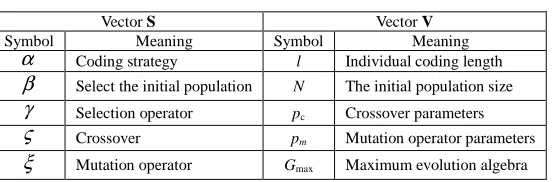
Genetic algorithm is an intelligent evolutionary computation method,involves a large number of evolutionary control strategies and control parameters in the implementation process, by designing strategy variables and control parameter variables , coordinating the relation between various factors , which aim to achieving the best optimal results. Here, the problem of camera calibration parameters optimization based on genetic algorithms is described as a function F with a three-dimensional mathematical model :
(
) (
) ( )
(
S V θ)
F α,β,γ,ζ,ξ , l,N,pc,pm,Gmax , f (10)
Where S——Genetic strategy vector that determines the states of existence and the evolutionary way of the state;
f— Fitness function is transformed from the optimal objective function , the optimal problem of camera parameters is a minimal extreme problem;Among,the vector of chromosome θ consists of all calibrated camera parameters to be as genetic constitution,expressed as
{
ω
,φ
,κ
,tx,ty,tz, f ,dx,dy,u0,v0,k1,k2,k3, p1, p2,b1,b2}
=
θ (11)
[image:5.595.171.447.188.279.2]Among,the respective components of the vector S and V of are described in Table 1.
Table 1 Notation of variables
Vector S Vector V
Symbol Meaning Symbol Meaning
α Coding strategy l Individual coding length
β Select the initial population N The initial population size
γ Selection operator pc Crossover parameters
ς Crossover pm Mutation operator parameters
ξ Mutation operator Gmax Maximum evolution algebra
Fitness function is the bridge and link associated the actual optimal problems with genetic algorithm,It will express the optimal objective as a function of influencing factors, through the evaluation of population fitness value of each individual to find the best combination of factors and achieve the problems of optimization. Camera calibration parameters is to make the camera image obtained by the imaging model and the actual image point coordinates of the square of distance between the observed values(u’i,υ’i) i=1,2,...,n and the obtained values (ui,υi) i=1,2,...,n is the minimum. Therefore, the definition of fitness function is
( ) ( )
[
]
{
[
( ) ( )
]
2}
1
2
)
( i r i r
n
i
r i r i
r u u v v
f θ =
∑
′θ − θ + ′θ − θ=
(12)
Among,(u’i(θr),υ’i(θr)) is the chromosome vector θr and the calibration control points Pi, obtained by the use of the camera imaging model pixel coordinate; (ui(θr),υi(θr)) is the actual coordinate of image observation between chromosome θr and calibration corresponding to the control point Pi.
In summary shows that the goal of the optimal camera parameter calibration is through determining the minimum value of the fitness function f(θ) to determine the optimal calibration results
( )
0 arg min
θ f θ
θ
= (13)
RESULTS
To validate the proposed camera calibration method parameter optimization, calibrating Kodak Megaplus1.4i camera parameters . Camera manufacturers provide physical parameters : the image plane size , focus, horizontal and vertical axis of a unit pixel size. Camera manufacturers provide the physical parameters: image plane size 1316pixel×1035pixel, focal length f=12mm, Horizontal and vertical directions of the unit pixel size dx=dy=6.8μm.
Fig. 3 Device for camera parameters calibration
Fig. 4 Dummy solid calibration template
For optimization using genetic algorithm to optimize the camera parameter calibration, need to set genetic algorithm parameters . As shown in table 3
Table 3 Parameters setup of GA
Set the parameters Choose to calculated parameters Crossover operator parameters
Number of values 0.08 0,1
Mutation operator parameters Population size Maximum running times
2,200,3 40 200
Based on the initial parameters in Table 3, generating a search scope of the optimized camera calibration parameters. Optimal Solving the calibration template 320 calibration controlled points of the 440 controlled points provided by the virtual three-dimensional calibration optimization solutions by genetic optimization algorithm, and ultimately determine the camera intrinsic parameters. Calibration results are shown in Table 4.
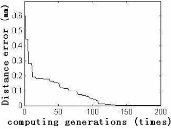
Figure 5 shows the use of genetic algorithms to optimize in the process of solving , evolving the relationships between algebra and optimization evolutionary of the objectives ,the optimization of search results rapidly converge to the optimal solution with the generation increases of evolutionary.
Fig. 5 Formulation of Optimization object and computation generation
[image:6.595.223.392.552.680.2]1. Stereo calibration error NSCE normalization formula is defined as
(
) (
)
(
)
1 2 ' '
' 2 2 1
1
12
n ci ci ci ci
i ci u v
X X Y Y NSCE
n= Z f− f−
− + −
=
+
∑
(14)Where, (X‘ci,Y’ci,Z‘ci) —— to calibrate the ideal values of the control point coordinates in the camera coordinate, can be determined by (Xwi,Ywi,Zwi).
(Xci,Yci)——the corresponding measurement value, can be determined by the image point coordinates(ui,υi). When NSCE≈1 calibration method has good performance.
Involved in optimizing the use of calibrated 320 control points calculated normalized stereo calibration error NSCE=1.028 , indicating that the algorithm has good performance.
Table 4 Calibration result of the camera internal parameters
Parameters f (mm) u0 (pixel) v0 (pixel) dx (µm)
Calibration values 12.088 -13.752 5.468 6.810
Parameters dy (µm) k1 k2 k3
Calibration values 6.803 -9.854×10⁻⁴ 4.855×10⁻⁴ 7.246×10⁻⁷
Parameters p1 p2 b1 b2
Calibration values 2.142×10⁻⁵ -6.061×10⁻⁵ 8.182×10⁻⁵ -3.113×10⁻⁵
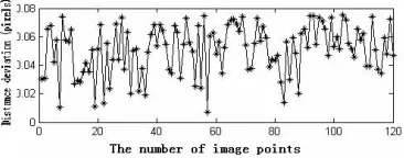
[image:7.595.210.393.382.454.2]2. The image distortion coordinate accuracy, will not optimize the control of the calibration of the image 120 of the observed value of the coordinates of the calibration control points from the three-dimensional space coordinates using the distortion factors to consider calibration model to obtain a distance between the estimated value of the difference as accuracy evaluation criteria. Figure 6 is a dot between the actual value and the estimated difference in distance .
Fig. 6 the discrepancy between real value and estimated result
Inverse calculation involved 120 image points ( not involved in optimizing calibration ) of the actual coordinate values using the known spatial calibration control points obtained by the camera imaging model the distance between the coordinate values of the mean error of 0.050 pixels, the standard deviation is 0.016 pixels , combined with analysis of figure 6 shows that the proposed algorithm has higher calibration accuracy.
CONCLUSION
This paper proposed the method of calibrated camera parameters optimization based on the genetic algorithm. In the ideal pinhole model, establishing a more comprehensive amendment calibration model based on the parameters; providing space for calibration control points through a virtual three-dimensional high-precision calibration template; establishing a legacy camera parameters optimization models and mathematical description of the fitness function. Finally, the experiment proves that the method is feasible, with high calibration accuracy, which meets precisely calibrated technical requirements of the visual measurement techniques camera parameters.
REFERENCES
[1] Liu Changying, Gao Le, GaoYinhan, et al. Journal of Jilin University ( Engineering and Technology Edition).