Wideband Patch Antenna Design for Wi-MAX and WLAN
Application with Modified Ground Plane
Gurpreet Kumar
Lovely Professional University Phagwara (Punjab), India
Pankaj Kumar Keshri
Lovely Professional University Phagwara (Punjab), India
Sunil Basra
Lovely Professional University Phagwara (Punjab), India
ABSTRACT
The Microstrip Patch Antenna design for new emerging technologies is an area of extensive research these days because of their low profile and ease of fabrication. Antenna design presented in this paper is well suited for Wi-MAX and WLAN application. The antenna is providing -10dB bandwidth of 4.14GHz from frequency 2.5GHz to 6.6GHz which is coming under the standards of these two technologies and good results have been achieved in the return loss and radiation pattern of the antenna. The design is made of FR4 substrate with modified ground plane structure and by inserting rectangular slits between feed line and radiating patch was implemented to change the effective length of the antenna. The radiation pattern of the antenna is presented using CST Microwave Studio which is well suited for wireless application.
Keywords
Wideband, Wi-MAX, WLAN , Slits, Modified ground plane, Radiating patch, DGS, FSS
1.
IINTRODUCTION
In many wireless applications it is required to design a patch antenna for multiple frequency band operation. The Microstrip Patch antennas are generally narrow band antennas and the design of Microstrip patch antennas for wideband applications is an area of extensive research [1]. There are multiple techniques which have been employed in Microstrip Patch Antennas to achieve the wideband operation such a cutting multiple slots(Uslot,Lslot) in the antenna, which makes the antenna resonate at multiple frequencies. The slots introduce the modes near the fundamental mode of resonant frequency of the patch and provide multiband operation. This makes the antenna design much more complex [2][6]. A new technique for designing the patch antenna has been introduced recently i.e. cutting the multiple U slots in suitable position to achieve the band notch at a frequency within the broadband [9]. A low profile antenna multiband PIFA having a stacked solar antenna combination was demonstrated. The design proposed solar PIFA was consisting of multisport loaded radiating PIFA element stacked with poly-Si solar cell working as a parasitic patch.
The operating frequency bands of 1.6-1.9GHz, 2.3-2.52GHz, 3.24-3.5GHz and 5.7-5.9GHz were achieved [7].The antenna with two rectangular slots on the patch and two elliptical slots in the ground plane providing triple band frequency of operation was presented[4].The antenna with simple probe feed having multiple U slots in the design was presented. When additional two slots were introduced in the
antenna it provided a triple band operation [8].An antenna with CPW feed for providing the wideband operation was presented. The antenna design proposed was having a
rectangular patch with cut off top corners and slot in the design [5].
An antenna with stacked geometry and inverted configuration for wideband application was presented [3].A monopole planner antenna with DGS (Defective Ground Structure) was presented for enhancing the bandwidth of the antenna and U slots was cut to achieve the band notch characteristics [9].A novel approach by using a FSS (Frequency Selective Surface) and by cutting multiple U-slots for WLAN and Wi-MAX application was presented. After introducing FSS in the design the bandwidths were improved in the design [10]. In this paper, A wideband antenna with modified ground plane and by introducing slits between the feed line and radiating patch is presented. The design meets the specifications of the WLAN (3.6GHz, 4.9GHz, 5GHz and 5.9GHz) and Wi-MAX (2.5GHz, 3.5GHz and 5.8GHz).The simulated effect of modified ground plane and feed position on the characteristics of the antenna is present using CST Microwave Studio.
2.
ANTENNA DESIGN GEOMETRY
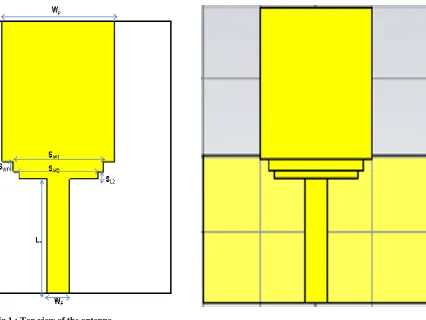
Figure 1 and 2 Shows the schematic diagram of the antenna which is proposed. The antenna is made onto FR4 substrate having dielectric constant of 4.3 and loss tangent of 0.025.The antenna volume including substrate and ground plane 38 40 1.59(2416.8mm3). Dimensions of the patch antenna are optimized by inserting slits between the patch and the Microstrip line feed and by modifying the ground plane to improve the return loss properties of the design. As can be seen in Figure 3 there are two rectangular slits of the same substrate and height as that of the patch are inserted between the patch and the Microstrip feed line. The slits that are being used in the design are optimized using Trust region framework available in the CST Microwave Studio. Microstrip Line feed has been used in the design and the position of feed in the design was changed to get the optimized results and good results were achieved when the feeding was provided at the center of the patch.
Fig 1 : Top view of the antenna
[image:2.595.114.541.67.387.2]Fig 2 : Bottom view of the antenna
Fig 3 : Top View of antenna showing rectangular slits between feed and radiating patch
[image:2.595.59.282.414.688.2]The detailed information about the dimensions of the design is given in the table I:
Table I. Detailed dimensions of the antenna
Parameter Dimensions (mm)
Parameter Dimensions (mm)
WP 20 SW1 13.6
LP 19.5 SL1 1.5
LF 16.5 SW2 12
WF 4 SL2 1
LGPS 22.8 LS 38
WGPS 3.51 WS 40
LGP 19 HS 1.59
WGP 40 MT 0.1
3.
RESULTS AND DISSCUSSIONS
[image:2.595.310.546.481.705.2]range in suitable for the Wi-MAX and WLAN standards.The minimum return loss of -47-194dB was achieved at 3.48GHz.The return loss plot of the antenna was optimized by creating a rectangular slot in the ground plane and the length and width of the slot was optimized to meet the specifications of the application. The introduction of the slits in the proposed design also improved the return loss properties of the antenna as they changed the effective length and width of the antenna so resonant frequency of the antenna was also changed and the optimization of the slits dimensions was done using Trust Region Framework in CST Microwave Studio.
Fig 4 : Return Loss (S11) of the antenna
For Licenced Wi-MAX frequecny band of 3.5GHz return loss of -44.175dB was achived in the simulated results and for other licenced and licence free bands, 2.5GHz and 5.8GHz return loss of -10.737dB and -16.233dB was achived.Similarly for WLAN standards maximum return loss of -31.914dB was achived at 3.6GHz in the simulated results and for other frequency bands i.e. 4.9GHz,5GHz and 5.9GHz the return loss of -19.214dB,-19.704dB and -15.275dB was achived.
3.1
Effect of Feed Position
[image:3.595.57.274.200.398.2]As can be seen in Figure 6 as the position of the feed is moved from centre to the left the antenna resonating frequency changes .Originally when feed was at centre the maximum return loss was at 3.57GHz.But as the feed point was changed to left the antenna effective area changes and the maximum point moves to lower frequencies i.e. 3.1 to 3.3GHz .So the feed position was kept at the centre of the patch where the return loss properties were well suited for the application of the antenna. But the effect of the movement of the feed position of the return loss properties of the antenna was seen in the simulated results of the antenna. The variation in the return loss properties of the antenna with change in the feed position is shown in figure 3.
Fig 5 : Return Loss (S11) plot showing the effect of change
in feed position
3.2
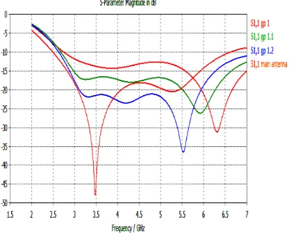
Effect of Ground Plane
The ground plane plays an important role in defining characteristics of the antenna. As can be seen in the figure as the length rectangular slot created in the ground plane was changed the resonant frequency of the antenna changes. The wideband characteristics of the antenna does not changes too much but the frequencies at which antenna i.e. maximum return loss changes to higher frequencies in the range 5.5 to 6.5GHz.The optimized length of the slot was 1.3mm.At this length the maximum return loss of the antenna was at 3.57GHz,which is appropriate for our application. But as the slot length was reduced the resonant frequency at which maximum return loss was achieved changes to higher frequency ranges i.e. for length of 1mm, 1.1mm and 1.2mm the maximum return loss was changed to 6.31GHz, 5.92GHz and 5.53GHz. Similarly the width of the rectangular slot created in the ground plane optimized to 22.8mm.
Fig 6 : Return Loss Plot showing the effect of change in the length of rectangular slot in the ground plane
4.
RADIATION PATTERN
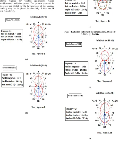
[image:3.595.324.532.477.645.2]antenna for frequencies in the WLAN standards are omnidirectional as well. In simulated results maximum directivity of 4.416dBi was achieved at frequency 5.9GHz which comes under the WLAN standards and minimum directivity 2.112dBi was achieved at 4.9GHz. For the other frequency ranges of the standards in WLAN and Wi-MAX application the directivity was lying between the ranges of the given maximum and minimum directivity respectively. So the antenna is a good candidate for these applications as the antenna required for wireless applications require omnidirectional radiation pattern. The patterns presented in this paper are plotted for the far field gain of the antenna. Similarly they can be plotted for directivity, E field and H field respectively.
(a)
(b)
[image:4.595.57.548.167.751.2](c)
Fig 7 : Radiation Pattern of the antenna (a) 2.5GHz (b) 3.5GHz (c) 5.8GHz
(a)
(c)
[image:5.595.62.287.77.511.2](d)
Fig 8 : Radiation Pattern of the antenna (a) 3.6GHz (b) 4.9GHz (c) 5GHz (d) 5.9GHz
5.
CONCLUSION
A wideband antenna with modified ground plane for Wi-MAX and WLAN application has been presented in this paper. The antenna provides -10dB bandwidth of 4.14GHz between frequency range of 2.5GHz to 6.6GHz.The introduction of rectangular slits in the design changed resonant frequency of the antenna and improved return loss(S11)was achieved in the simulation results on CST Microwave Studio. The radiation patterns of the antenna are omnidirectional for all for all frequency bands and the structure of the antenna is simple and can be easily design. Good results in radiation efficiency and gain of the antenna
have been achieved, which makes is well suited for wireless application. For future work the thickness of the substrate could be changed and the use of metamaterials could improve the directivity and gain of the antenna.
6.
REFERENCES
[1] Constantine.A.Balanis “Antenna Theory Analysis and Design” ,Third Edition ,pp.811-882, JOHN WILEY & SONS, INC., PUBLICATION,2005
[2] Kin-Lu Wong “Compact and Broadband Microstrip Antennas” Third Edition,pp.45-79, JOHN WILEY & SONS, INC. PUBLICATION,2002
[3] Umair Rafique, Syed Ahsan Ali, M. Arif Khan and M. Mansoor Ahmed “A Wideband Slot-Coupled Inverted Microstrip Patch Antenna for Wireless Communications” ©2012 IEEE
[4] M.Samsuzzaman, N. Misran2, J.S Mandeep, M.T. Islam “An inverted S-shaped multi-frequency patch antenna for X band applications” ©2013 IEEE
[5] Md Shaad Mahmud, Fawwaz Jinan Jibrael Jabri” Wideband Microstrip Patch Antenna for WLAN and WiMAX Applications on Liquid Crystal Polymer Substrate” ©2013 IEEE
[6] [6] H. Nornikman, , F. Malek, N. Saudin, M. Md. Shukor, N. A. Zainuddin, M. Z. A. Abd Aziz, B. H. Ahmad,M. A. Othman1 “Design of Rectangular Stacked Patch Antenna with Four L-Shaped Slots and CPW-Fed for WiMAX Application” 2013 3rd International Conference on Instrumentation, Communications, Information Technology, and Biomedical Engineering (ICICI-BME) Bandung, November 7-8, 2013
[7] Okan Yurduseven, David Smith “A Solar Cell Stacked Multi-Slot Quad-Band PIFA for GSM, WLAN and WiMAX Networks” IEEE MICROWAVE AND WIRELESS COMPONENTS LETTERS, VOL. 23, NO. 6, JUNE 2013
[8] Wing Chi Mok, Sai Hoi Wong, Kwai Man Luk, and Kai Fong Lee “Single-Layer Single-Patch Dual-Band and Triple-Band Patch Antennas” IEEE TRANSACTIONS ON ANTENNAS AND PROPAGATION, VOL. 61, NO. 8, AUGUST 2013
[9] Lipsa Das, Abhishek Sahoo, Diptimayee Konhar, Debasis Mishra” A Planar Monopole Antenna with DGS for bandwidth Enhancement and U-slot for band-notch characteristics” Proceedings of 2013 IEEE Conference on Information and Communication Technologies (ICT 2013)