ISSN: 1992-8645 www.jatit.org E-ISSN: 1817-3195
IMAGE COMPRESSION USING WAVELET TRANSFORM
AND GRAPH CUT ALGORITHM
1VASANTHI KUMARI P AND 2K THANUSHKODI
1Coimbatore Institute of Engineering and Technology, Coimbatore 2Director, Akshaya College of Engineering and Technology, Coimbatore
E-mail: [email protected]
ABSTRACT
The need for an efficient technique for compression of images is ever increasing because, the raw images need large amounts of disk space seems to be a big disadvantage during transmission and storage. Even though, there are so many compression techniques already present, a better technique which is faster, memory efficient and simple surely suits the requirements of the user. This paper presents image compression technique using graph cut and wavelet transform. At first, block partitioning process is carried out which is quantized and subsequently, graph cut algorithm is applied to select the dissimilar blocks. DPCM (Differential pulse-code modulation) is consequently applied for increasing the compressibility of an image. Finally, the transformed image is given to Huffman-encoder that is designed by merging the lowest probable symbols in such a way that, the images get compressed. The proposed image compression is implemented using MATLAB and the performance of the proposed technique is compared with the wavelet-based previous techniques and DCT method. From the results, it can be inferred that our proposed technique have outperformed the existing techniques.
Keywords: Image compression, Discrete Wavelet Transform, Graph Cut algorithm, Differential Pulse-Code Modulation (DPCM), Huffman-coding.
1. INTRODUCTION
During the transmission and storage of raw images it requires huge quantity of disk space and hence, there is an urgent requirement to reduce the size of image before sending or storing [8]. The best possible to the problem is to use compression methods where the compression of data on digital images are made to reduce irrelevance and redundancy of the image data in order to be able to store or transmit data in an efficient from [9]. Most of the existing compression techniques employed have their negatives and an enhanced technique which is faster, effective and memory efficient can definitely satisfy the requirements of the user [8]. Image compression thrives to store or transmit the data in a proficient mode as well as to offer a best image quality at a specified bit-rate.
Image compression can be done in lossy or lossless mode [10]. Lossless compression is preferred for archival objectives and mainly used in medical imaging, technical drawings, clip art, or comics. This is because of the introduction of compression artifacts, low bit rates and also that the resources cannot be saved considerably by using this image compression
method. Lossy methods are especially suitable for natural images such as photographs in applications where negligible loss of fidelity is tolerable to attain a considerable reduction in bit rate. Here conciliated ensuing image quality devoid of much perceive of the viewer is achieved [11,12]. Recently, studies on the wavelet theory [12] and its application to the image compression field have been increasingly carried out [20,21]. The subject is adequately novel and additional progression is needed to improve on the quality [17].
ISSN: 1992-8645 www.jatit.org E-ISSN: 1817-3195
processing power. The compression phase consists of three sequential steps of transformation, quantization and encoding. For transformation Discrete Cosine transform or Discrete Wavelet can be used [16]. The quantization is carried out after DWT process, where a set of values is compressed to a single quantum value making the given stream more compressed, when the number of discrete symbols in a stream is reduced. Generally, for coding entropy coding is used which can provide a much shorter image representation by using short code words for probable images and longer code words for less probable images [17]. Shannon-Fano entropy, Huffman coding, Kolmogorov entropy and arithmetic coding are various types of entropy coding used in various applications [18]. The quality of a compression method often is measured by the Peak signal-to-noise ratio where it measures the amount of noise introduced through a lossy compression of the image.
In our technique, initially after pre-processing using Gaussian filtering, block partitioning process is carried out where image is split into separate blocks. Then, graph cut algorithm will be applied to select the dissimilar blocks. The desired cut will be performed based on the dissimilarity so that the connected blocks are chosen to find the
representative of the blocks to perform wavelet
computation. Then, DPCM (Differential pulse-code modulation) is applied for increasing the compressibility of an image. Finally, the transformed image is given to Huffman-encoder that is designed by merging the lowest probable symbols in such a way that, the images get compressed. For decompression, the Huffman decoding procedure is applied in the compressed image. Furthermore, the inverse DPCM and inverse DWT is applied on the decoded data to obtain the decompressed image.
The main contribution of the paper is discussed as follows:
• Efficient image compression using wavelet transform and graph cut algorithm.
• Application of graph cut leads to greater image compression.
• Use of DPCM and Huffman encoding to increase the compressibility.
• Comparison to existing compression technique to evaluate the performance of the proposed technique.
The paper is organized as follows: The review of recent works is described in section 2, proposed image compression technique is described in
section 3, results are described in section 4 and finally, the conclusion is given in section 5.
2. RELATED WORKS
In the literature, a handful of works based on image compression are presented and in this section, we discuss some of the prominent works. Chopra and A.K.Pal [1] improved the geometric wavelet (GW) image coding method by the use of the slope intercept representation of the straight line in the binary space partition scheme. The performance of the proposed algorithm was compared with the wavelet transform-based compression methods such as the embedded zero tree wavelet (EZW), the set partitioning in hierarchical trees (SPIHT) and the embedded block coding with optimized truncation (EBCOT), and sparse geometric representation based compression algorithms and found that the proposed technique performed well. Arun Vikas Singh and Srikanta Murthy K [2] have proposed a image compression algorithm which combined the feature of both wavelet transform and Radial Basis Function Neural Network along with vector quantization. First the images were decomposed into a set of subbands having different resolution with respect to different frequency bands using wavelet filters. Based on their statistical properties, different coding and quantization techniques were employed. The Differential Pulse Code Modulation (DPCM) was used to compress the low frequency band coefficients and Radial Basis Function Neural Network (RBFNN) was used to compress the high frequency band coefficients. In terms of peak signal to noise ratio (PSNR) and computation time (CT), a large compression ratio was achieved with satisfactory reconstructed images in relation to the existing methods by using the proposed technique.
ISSN: 1992-8645 www.jatit.org E-ISSN: 1817-3195
mean recovering. This is done in order to guarantee that a desired quality was checked. For the aim to obtain the best possible compression ratio CR, the next step was the application of a proposed adaptive scanning. The last step was the application of a modified systematic lossless encoder and the efficiency of the proposed scheme was demonstrated by results. X. Zhang [5] proposed a scheme for lossy compression of an encrypted image with flexible compression ratio. A pseudorandom permutation was used to encrypt an original image, and the encrypted data were efficiently compressed by discarding the excessively rough and fine information of coefficients generated from orthogonal transform.
C. Hemasundara Rao and M. Madhavi Latha [6] have presented a reversible blockade transform coding based hybrid image compression method. The method that implemented over the regions of interest (ROIs) was based on the selection of the coefficients that belong to diverse transforms. The method allows: (i) codification of many kernals at different levels of interest, (ii) arbitrary shaped spectrum, and (iii) adaptable adjustment of the compression quality of the image and the background. As well, it was not necessary for performing standard modification for JPEG2000 decoder. The method was applied over diverse types of images. Results have showed that a better performance has been achieved for the selected regions, when image coding techniques are used for
the entire set of images. Xixin Cao et al. [7] have proposed Discrete Wavelet Transform based on Distributed Arithmetic for image compression. It considered the periodicity and symmetry of DWT to increase the performance as well as to reduce the computational redundancy. The inner product of coefficient matrix of DWT was distributed over the input by careful analysis of input, output and coefficient word lengths. This design was very applicable for image compression systems such as JPEG2000 and MPEG4.
3. PROPOSED IMAGE COMPRESSION USING WAVELET TRANSFORM AND GRAPH CUT ALGORITHM
In this section, we discuss the proposed image compression technique using graph cut and DWT (Discrete Wavelet Transform). Initially, block partitioning process is carried out and then applied DWT. Subsequently, graph cut algorithm and DPCM (Differential pulse-code modulation) is applied for increasing the compressibility of an image. Finally, the transformed image is given to Huffman-encoder so as to complete the compression. For decompression, the Huffman decoding procedure is applied in the compressed image. Furthermore, the inverse DPCM and inverse DCT is applied on the decoded data to obtain the decompressed image. The complete block diagram of the proposed technique is given in figure 1.
Figure 1: Block Diagram Of Proposed Technique
a) Block Partitioning Module
The input image is initially preprocessed using Gaussian filter which reduces noise in the input image and also makes the image robust for further operations. Gaussian filter is an example of linear filter which is usually used to eliminate noise and improve on the image quality. It is also a window filter and is named after famous scientist Carl Gauss. The filter computes the weighted
average using Gaussian distribution which is a probability theory function and also called bell-function because of its shape. Gaussian filter can be used for both one-dimensional and two dimensional cases.
ISSN: 1992-8645 www.jatit.org E-ISSN: 1817-3195
dimension
N
×
M
is partitioned into blocksB
i,where
i
=
{
1
,
2
,
,
K
}
,N
is the total number of pixel rows in the image,M
is the number of column pixels in the image,K
is the total numberof blocks and the size of each small block be
defined by
c
×
d
so that we have,d
c
K
M
[image:4.612.141.471.166.306.2]N
×
=
×
×
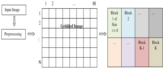
. Block diagram of the block portioning module is given in figure 2.Figure 2: Block Diagram Of Block Partitioning Module
b) Graph Cut Module
Once the image is converted to small blocks in the block partitioning module, the Discrete Wavelet Transform is performedwhere the input image is transformed into the wavelet coefficients. The coefficients are quantized and subsequently, graph cut algorithm is applied to select the dissimilar blocks.
i) DWT
Wavelet series is a representation of a square-integrable function by a certain ortho-normal series generated by a wavelet and Discrete Wavelet Transform (DWT) is any wavelet transform for which the wavelets are discretely sampled. Use of DWT lessens the computation time with required resources and is simple to implement. In DWT, various frequency bands along with different resolutions are made use of in order to transform the signalto coarse approximation and detail information. When the signals are passed through the low pass filter, high frequency components are eliminated and the approximation components gain. The scale is not affected and the resolution gets reduced to half. Subsequently, half the redundant
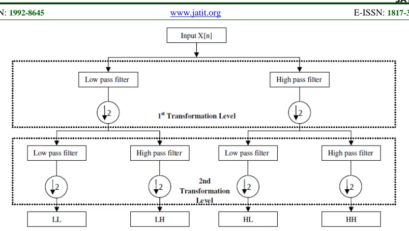
samples are eliminated through sub sampling where it does not affect the resolution which gets doubled, but affects the scale. Similarly, the detail coefficients are attained by passing the signal through the high pass filter. The values are multiplied again with the low pass and high pass filter coefficients to obtain the LL, LH, HL and HH bands. Figure 3 gives the block diagram to compute the wavelet coefficients and in general, the wavelet transform of the image can be calculated by the formulas:
k] -G[n X[k] ]
[ =
∑
k Low nW ,
k] -F[n X[k] ]
[ =
∑
k HIGH n W
ISSN: 1992-8645 www.jatit.org E-ISSN: 1817-3195
Figure 3: Block Diagram Of Wavelet Transform
ii) Graph cut algorithm
The quantized DWT transformed coefficients are then applied Graph cut algorithm which basically does the operation of segmentationof the image so as to formsegments having similar blocks or in other words select the dissimilar blocks. Graph cut provides a clean, flexible formulation for image segmentation and provides a convenient language to encode simple local segmentation cues, and a set of powerful computational mechanisms to extract global segmentation from these simple localpixel similarities. In the graph cut, the image pixels are interconnected to form the shape of a graph. In graph cut, theses interconnections are evaluated and a cut is made when two pixels differ by an amount. When a cut is made it forms to two segments and the process is continued to form segments. In graph cut, the whole image is represented as graph where, every node signifies a block and the edge weight is the dissimilarity value in between the blocks. Then, the desired cut is performed based on the dissimilarity so that the connected blocks are
chosen to find the representative of the blocks to
perform wavelet computation.
Here the advantage of using graph cut is that blocks are similar properties are found out. Let the image be represented as blocks of
}
,...,
,
{
B
1B
2B
VB
=
whereV
is the total numberof blocks. After applying graph cut algorithm,
various blocks
B
1,
B
2and
B
8 having similarproperties will be found out and grouped under one
segment
S
i,
where
0
<
i
≤
W
andW
is thenumber of segments formed. Suppose say that block
are having similar properties and grouped under one segment. The advantage of finding this similarity lies in the fact that only one of block in the same segment needs to be encoded and this will effectively save space when it comes to compression. That is, in the earlier example instead
of encoding blocks
B
1,
B
2and
B
8, we need toencode only one of these blocks say block
B
1. Hence, by the use of graph cut similar blocks are found out and any one of the block under the segment is encoded, which greatly contributes to better compression. The selected block to represent the segment is termed representative block and these blocks are encoded whereas other blocks which in the segment uses the earlier of the earlier encoded representative block. This will lead to better compression as all the blocks need not be encoded rather only representative blocks need to encoded.c) Encoding Module
After performing the graph cut algorithm on the wavelet transformed image, it is done DPCM coding and then done Huffman coding.
ISSN: 1992-8645 www.jatit.org E-ISSN: 1817-3195
forecast wavelet coefficients
W
F are obtained using the equation:M k n W
W
M
k F
F
∑
=
− = 1
) (
Subsequently, the residual coefficients are found
[image:6.612.103.499.70.333.2]by:
C
R=
W
F−
W
F. The block diagram of DPCM transform is shown in figure 4.Figure 4: DPCM Transformation
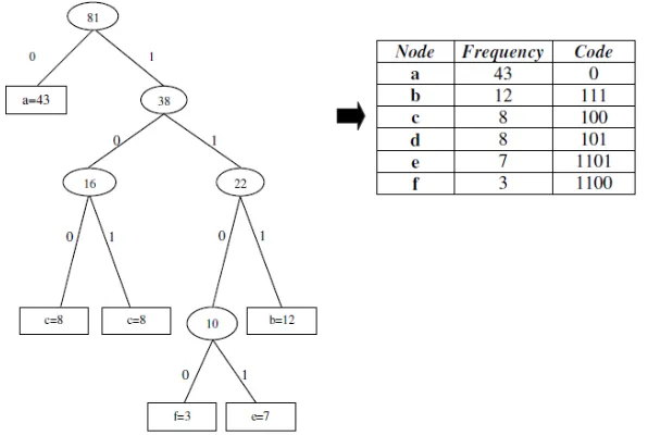
After getting the residual coefficients from the DPCM coding, Huffman coding is used to convert it into the bit stream. At first, we attain the frequency of the residual coefficients that is structured in the ascending order. Subsequently, two nodes having lowest frequency count are merged and the new node value is the addition of two selected node values. Consequently, similar
methodology is repeated for every node until a single node is obtained. Finally, the binary value is allocated to every node depending on the right or left wing of the node. Then, each value obtains one code vector that is used to build the bit stream of the input image stored instead of the image. Example of Huffman coding is given in figure 5.
[image:6.612.160.458.472.678.2]ISSN: 1992-8645 www.jatit.org E-ISSN: 1817-3195
d) Decompression module
The process of decompression is simply a matter of translating the stream of prefix codes to individual byte values, usually by traversing the Huffman tree node by node as each bit is read from the input stream. Furthermore, the inverse DPCM and inverse DWT is applied on the decoded data to obtain the decompressed image.
When the variables are stored using Huffman coding, codes are converted to equal length by prefixing zeros. In the decoding process, input bit stream is converted back to variable names and then to the corresponding frequency count. If the input stream is 110011010101, then it is decoded as FED.
4. RESULTS AND DISCUSSIONS
The proposed technique for image compression is evaluated and discussed in this section. Section 4.1 gives the experimental set up and the evaluation metrics employed. The experimental results are discussed in section 4.2 and performance analysis is made in section 4.3.
4.1 Experimental Set Up and Evaluation Metrics
The proposed technique is implemented in MATLAB on a system having 6 GB RAM and 2.6 GHz Intel i-7 processor. The evaluation metrics used is peak signal-to-noise ratio (PSNR) and Compression ratio. PSNR is defined as the ratio between the maximum possible power of the signal and the power of noise that influences the fidelity of its representation. The PSNR is most commonly used as a measure of quality of reconstruction of lossy compression techniques. The signal in this case is the original data, and the noise is the error introduced by compression. PSNR can be mathematically represented as:
MSE
I
PSNR
2 max 10
log
10
=
Where,
I
max is the maximum intensity is theimage and
MSE
is the mean squared error. Compression ratio is the ratio of size of the compressed image using proposed technique compared to that of the uncompressed input image.4.2 Experimental Results
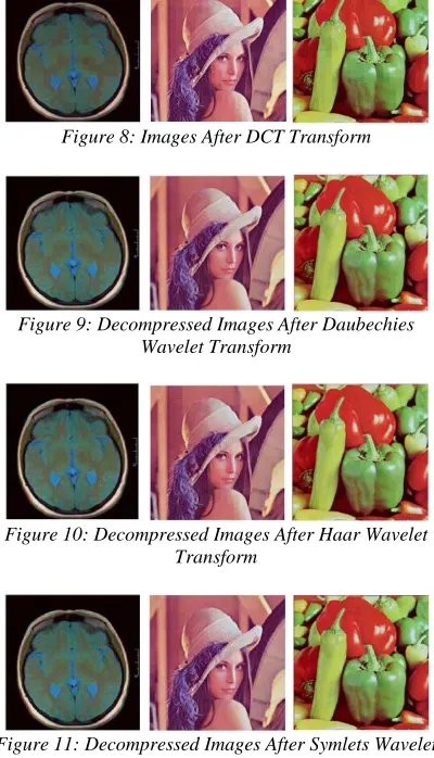
The experimental results obtained for the technique are given in this section. The input images are shown in figure 6. The images taken for evaluation are that of brain image, Lena image and vegetable image. Figure 7 gives the segmented images using graph cut and figure 8 gives after
DCT transformation. Figure 9, 10 and 11 gives the decompressed images by the use of Daubechies, Haar and Symlets wavelet transforms.
[image:7.612.317.519.145.293.2]Figure 6: The Sample Input Images
[image:7.612.318.518.325.674.2]Figure 7: Images After Graph Cut Segmentation
Figure 8: Images After DCT Transform
Figure 9: Decompressed Images After Daubechies Wavelet Transform
Figure 10: Decompressed Images After Haar Wavelet Transform
Figure 11: Decompressed Images After Symlets Wavelet Transform
4.3 Performance Analysis
ISSN: 1992-8645 www.jatit.org E-ISSN: 1817-3195
[image:8.612.117.500.164.339.2]compression ratio and PSNR values obtained for the proposed technique and old technique is given in figure 12. We have made use of Daubechies, Haar and Symlets wavelet transformation for the proposed technique.
[image:8.612.94.298.370.677.2]Figure 12: Chart Showing The Evaluation Metrics Obtained
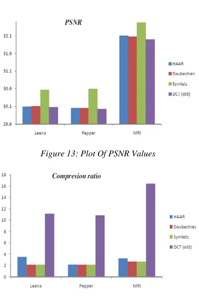
Figure 13: Plot Of PSNR Values
Figure 14: Plot Of Compression Ratio
Figure 13 and 14 shows the plot of PSNR values and compression ratio. From the graphs, it is
evident that our proposed technique (using Symlets) has performed well earning better PSNR.
5. CONCLUSION
In this paper, we present the proposed image compression technique using graph cut and DWT. Initially, block partitioning process is carried out and then applied DWT. Subsequently, graph cut algorithm and DPCM is applied for increasing the compressibility of an image. Finally, the transformed image is given to Huffman-encoder so as to complete the compression. For decompression, the Huffman decoding procedure is applied in the compressed image. Furthermore, the inverse DPCM and inverse DWT is applied on the decoded data to obtain the decompressed image. The proposed image compression is implemented using MATLAB and the performance of the proposed technique is compared with the previous techniques. Form the results, it can be inferred that our proposed technique have outperformed the existing techniques.
REFERENCES
[1] Chopra and A.K.Pal, "An Improved Image Compression Algorithm Using Binary Space Partition Scheme and Geometric Wavelets",
ISSN: 1992-8645 www.jatit.org E-ISSN: 1817-3195
[2] Arun Vikas Singh and Srikanta Murthy K , "Neuro-Wavelet based Efficient Image Compression using Vector Quantization",
International Journal of Computer Applications, Vol.49, No.3,pp.33-40, 2012.
[3] Jau-Ji Shen and Ya-Hsin Lo," A New Approach of Image Compression Based on Difference Vector Quantization" In proceedings of
International Conference on Intelligent Information Hiding and Multimedia Signal Processing (IIH-MSP),p.137-140, 2011.
[4] Fouzi Douak, Redha Benzid and Nabil Benoudjit, "Color imagecompression algorithm based on the DCT transform combined to an adaptive block scanning", International Journal of Electronics and Communications, Vol.65, No.1, pp.16-26, 2011.
[5] Xinpeng Zhang, "Lossy Compression and Iterative Reconstruction for Encrypted Image",
IEEE Transactions on Information Forensics And Security, Vol. 6, No. 1, March 2011. [6] C. Hemasundara Rao and M. Madhavi Latha,
"A Novel VLSI Architecture of Hybrid Image Compression Model based on Reversible Blockade Transform", World Academy of Science, Engineering and Technology, Vol: 52, 2009.
[7] Xixin Cao, Qingqing Xie, Chungan Peng, Qingchun Wang, Dunshan Yu, "An Efficient VLSI Implementation of Distributed Architecture for DWT", proceedings of the IEEE 8th Workshop on Multimedia Signal Processing, , pp. 364 - 367, 2006.
[8] Jagadish H. Pujar, Lohit M. Kadlaskar, “A New Lossless Method Of Image Compression And Decompression Using Huffman Coding Techniques”, Journal of Theoretical and Applied Information Technology, Vol. 15, No.1, 2010.
[9] P.J. Burt, E.H. Adelson, “The Laplacian Pyramid as a Compact Image Code”, IEEE Trans. on Communications, pp. 532–540, 1983.
[10]C. Hemasundara Rao and M. Madhavi Latha, "A Novel VLSI Architecture of Hybrid Image Compression Model based on Reversible Blockade Transform", World Academy of Science, Engineering and Technology, Vol: 52, 2009.
[11]Chengjiang Lin, Bo Zhang, and Yuan F. Zheng “Packed Integer Wavelet Transform Constructed by Lifting Scheme” IEEE Transactions on Circuits And Systems For Video Technology, Vol. 10, No. 8, 2000.
[12]G. K. Kharate, A. A. Ghatol and P.P. R “Image Compression Using Wavelet Packet Tree”
ICGST-GVIP Journal, Vol: 5, No: 7, 2005. [13]R. Calderbank “Wavelet Transforms That Map
Integers to Integers”, Applied and
computational harmonic analysis, pp. 332–369, 1998.
[14]Adrian Munteanu, Jan Cornelis and Paul Cristea. “Wavelet-Based Lossless Compression of Coronary Angiographic Images” IEEE transactions on medical imaging, Vol. 18, No. 3, 1999.
[15]Shilpa S. Dhulap and Sanjay I. Nalbalwar, "Image Compression Based on IWT, IWPT & DPCM-IWPT", International Journal of Engineering Science and Technology, Vol. 2, No. 12, pp. 7413-7422, 2010.
[16]Mountassar Maamoun, Abderrahmane Namane, Mehdi Neggazi, Rachid Beguenane, Abdelhamid Meraghni and Daoud Berkani, "VLSI Design for High-Speed Image Computing Using Fast Convolution-Based Discrete Wavelet Transform", Proceedings of the World Congress on Engineering, Vol I, London, U.K, July 1 - 3, 2009.
[17]Geoffrey M. Davis, Aria Nosratinia, “Wavelet-based image coding: An overview”, Applied and Computational Control, Signals, and Circuits, 1998.