Copyright to IJIRSET www.ijirset.com 13507
Flow Visualization around Perforated
Circular Finned Tubes by CFD.
Yogesh Pal1, Naushad Ahmad Ansari2, M. Zunaid3
U.G Student, Department of Mechanical Engineering, Delhi Technological University, Delhi, India1
Assistant Professor, Department of Mechanical Engineering, Delhi Technological University, Delhi, India2
Assistant Professor, Department of Mechanical Engineering, Delhi Technological University, Delhi, India3
ABSTRACT: Rate of heat transfer increases by several folds with the increase in the surface area of heat exchangers, in practice this is often achieved by having fins at the surface of heat exchangers. The objective of the present study was to visualize the air flow around perforated circular finned tube (PCFT) through computational fluid dynamics (CFD). The air-side flow was visualized through simulation in fluent. Visualization of flow of air around the tube and fin for various cases were studied. These cases include the different positions of perforations on fins with respect to stagnation point. The different positions selected for perforations with respect to stagnation point are no holes and holes at an angle of 90 degree, 100 degree, 110 degree, 115 degree, 120 degree, 140 degree, 145 degree, 150 degree, 160 degree, and 170 degree. Gambit was used for construction of geometry and k-epsilon model was used for flow visualization. The perforation at an angle of 120 degree with respect to stagnation point was found to be the best location because recirculation of flow at this location found to be least. However perforations at the angles greater than 90 degree but less than 170 degree were effective in reducing the recirculation.
KEYWORDS: CFD; Flow visualization,Perforated circular fins, Recirculation, Stagnation point.
I. INTRODUCTION
ISSN: 2319-8753
I
nternational
J
ournal of
I
nnovative
R
esearch in
S
cience,
E
ngineering and
T
echnology
(An ISO 3297: 2007 Certified Organization)
Vol. 3, Issue 6, June 2014
Copyright to IJIRSET www.ijirset.com 13508 angle (q) increases, the more the crease cycle (l) decreases, and the more the number of holes (N) increases, the more the pressure loss and heat transfer performance increase together [11].
The objective of the present study was to visualize the air flow around perforated circular finned tube (PCFT) through computational fluid dynamics (CFD) only for 2-holes case because Lee et al. [4] investigated that in the case of the 4-hole PCFT there is a greater pressure drop which might be due to excessive flow disturbances produced by multiple perforations.
II. FLOWVISUALIZATIONPROCEDURE
Visualization of air flow around the tube and fin for various positions of perforations on fins with respect to stagnation point are studied. The positions selected for perforations are no holes and holes at an angle of 90 degree, 100 degree, 110 degree, 115 degree, 120 degree, 140 degree, 145 degree, 150 degree, 160 degree, and 170 degree with respect to stagnation point. Visualization of flow was carried out in following steps.
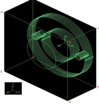
1. Physical model- the construction of geometry was done on gambit 2.4.6. The geometry consisted of a tube of length (along z-axis) 8 centimetres and radius 5 centimetres on which six circular fins were attached of radius 10 centimetres and thickness 0.2 centimetres. Spacing between the fins were taken at 0.5 centimetres. The whole apparatus was then enclosed in a brick of dimensions 22×22×10 centimetres. Due to uniform air flow parallel to fins, flow visualization was done for only for symmetry face as shown in figure below:
Fig. 1 Tube and fin geometry enclosed in a brick (flow volume)
2. Boundary conditions-to simulate the air flow boundary conditions have been given to the required faces. In figure
Copyright to IJIRSET www.ijirset.com 13509
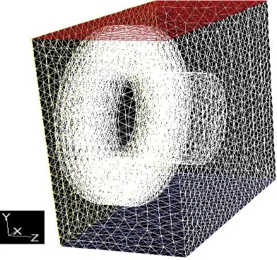
Fig. 2Meshed volume
3. Simulation- after exporting a mesh file from gambit by selecting solver as fluent 5/6. The mesh file was read on fluent 6.3.26. Scale factor was applied to have length of grids in centimetres. After that k-epsilon model was selected. Thetransport Equations for the Standard k-epsilon Model are as follows:
(1) and
(2) The turbulence kinetic energy, k, and its rate of dissipation, ɛ, are obtained from these equations. In these equations, Gk represents the generation of turbulence kinetic energy due to the mean velocity gradients, Gb is the
generation of turbulence kinetic energy due to buoyancy, YM represents the contribution of the fuctuating
dilatation in compressible turbulence to the overall dissipation rate, C1ɛ, C2ɛ, and C3ɛare constants.sk and seare
the turbulent Prandtl numbers for k and ɛ, respectively. Skand Sɛ are user-defined source terms.
ISSN: 2319-8753
I
nternational
J
ournal of
I
nnovative
R
esearch in
S
cience,
E
ngineering and
T
echnology
(An ISO 3297: 2007 Certified Organization)
Vol. 3, Issue 6, June 2014
Copyright to IJIRSET www.ijirset.com 13510
III.EXPERIMENTALRESULTS
After displaying velocity path lines, flow of air around the tubes and fins could be visualized. Some important figures are shown below:
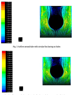
Fig. 3 Airflow around tube with circular fins having no holes
Copyright to IJIRSET www.ijirset.com 13511
Fig. 5 Airflow around tube with circular fins having holes at 120 degree
Fig. 6 Airflow around tube with circular fins having holes at 150 degree
ISSN: 2319-8753
I
nternational
J
ournal of
I
nnovative
R
esearch in
S
cience,
E
ngineering and
T
echnology
(An ISO 3297: 2007 Certified Organization)
Vol. 3, Issue 6, June 2014
Copyright to IJIRSET www.ijirset.com 13512 From figure 3 which was the case of plane fins, it can be seen that there is separation and detachment of air flow from the tube at an angle of approximately 120 degree with respect to stagnation point. In the case of two holes at an angle of 90 degree i.e. figure 4, it can be seen there is more recirculation of air flow around fins as compared to the case of fins without holes. As the angle increases beyond 90 degree, recirculation is decreasing that can be observed in figure 5 i.e. the case of holes at 120 degree in which recirculation is disappeared to a greater extent. As the angle further increases which is closed to 170 degree, recirculation is found to be more than the case of plane fins, this can be observed in figure 7.According to Lee et al. [4] the separation and detachment of air flow were delayed by introducing the perforations at the flow-separation locations on the finned tube, and the recirculation region was thus decreased thereafter. As we see in figure 3 that flow separation is taking place at an angle of approximately 120 degree with respect to stagnation point in the case of plane fins. Therefore, perforations at 120 degree on fins are most effective in reducing the separation and detachment of air flow. Hence, the above result could be validated.
IV. CONCLUSION
From above discussion it can be concluded that the perforations at an angle of 120 degree with respect to stagnation point is the best location because recirculation of air flow is vanishing up to a greater extent in this case. Hence there could be more convective heat transfer obtained between fluid flowing inside the tube and air flowing over the tube. This result might be helpful in reducing size of heat exchangers because with perforations on the fins, a higher value of convective heat transfer coefficient could be obtained as compared to the plane fins. Also, further investigations are recommended to study the effect of size of hole on recirculation region.
REFERENCES
[1] Yunus A.Cengel,“Text book of heat transfer a practical approach”, Tata McGraw-Hill second edition, 2002.
[2] M. Lee, T. Kang, Y. Kim,“Air-side heat transfer characteristics of spiral-type circular fin-tube heat exchangers”, International Journal of Refrigeration vol. 33, no. 2, pp. 313–320, 2010.
[3] M. Lee, T. Kang, Y. Joo, Y. Kim,“Heat transfer characteristics of spirally-coiled circular fin-tube heat exchangers operating under frosting conditions. International Journal of Refrigeration”,vol. 34, no. 1, pp. 328–336, 2011.
[4] Dong H. Lee, Jin M. Jung, Jong H. Ha, Young I. Cho,“Improvement of heat transfer with perforated circular holes in finned tubes of air-cooled heat exchanger”, International Communications in Heat and Mass Transfer,vol. 39, pp. 161–166, 2012.
[5] A. Nuntaphan, T. Kiatsiriroat, C. Wang,“Air side performance at low Reynolds number of cross-flow heat exchanger using crimped spiral fins”, International Communications in Heat and Mass Transfer, vol. 32, no. 1–2, pp. 151–165, 2005.
[6] C.C.Wang, J. Lo, Y.T. Lin, C.S.Wei,“Flow visualization of annular and delta win let vortex generators in fin-and-tube heat exchanger application”, International Journal of Heat and Mass Transfer, vol. 45, no. 18, pp. 3803–3815, 2002.
[7] Muhammad Mahmood AslamBhutta, Nasir Hayat, Muhammad Hassan Bashir, AhmerRais Khan, KanwarNaveed Ahmad, Sarfaraz Khan,“CFD applications in various heat exchangers design: A review”, Applied Thermal Engineering,vol. 32, pp. 1-12, 2012.
[8] A.G. Kanaris, A.A. Mouza, S.V. Paras,“Flow and heat transfer prediction in a corrugated plate heat exchanger using a CFD code”, Chem. Eng. Technol, vol. 8, pp. 923-930, 2006.
[9] Y. Wang, Q. Dong, M. Liu,“Characteristics of fluid flow and heat transfer in shell side of heat exchangers with longitudinal flow of shell side fluid with different supporting structures”, International Conference on Power Engineering, Hangzhou, China, pp.23-27,2007.
[10] Varun Singh, Omar Abdelaziz, Vikrant Aute, ReinhardRadermacher,“Simulation of air-to refrigerant fin-and-tube heat exchanger with CFD-based air propagation”, International journal of refrigeration, vol. 34, pp. 1883-1897, 2011.
[11] Chan HyeokJeong, HyungRak Kim, Man Yeong Ha, Sung Wan Son, Jae Seok Lee, Pan Yeong Kim,“Numerical investigation of thermal enhancement of plate fin type heat exchanger with creases and holes in construction machinery”,Applied Thermal Engineering,vol. 62, pp. 529-544, 2014.
BIOGRAPHY Yogesh pal
He is a final year student at Delhi Technological University pursuing B.tech in mechanical engineering. This paper is his first publication in the field of research and technology. Currently, he is working on ‘heat transfer modeling of heat exchangers by cfd’.
Naushad Ahmad Ansari
Copyright to IJIRSET www.ijirset.com 13513 in1995. Major field of study is Refrigeration and Air-Conditioning, Fluid Mechanics & CFD, Heat and mass transfer and I.C. Engine. published research papers are “Theoretical Exergy Analysis of HFO-1234yf and HFO-1234ze as an Alternative Replacement of HFC-134a in Simple Vapour Compression Refrigeration System’’. International journal of Scientific and Engineering Research, vol.4, Issue8, 137-144, 2013,“Exhaust Gas Analysis and Parametric Study of Ethanol Blended Gasoline Fuel in Spark Ignition Engine’’. American journal of Engineering Research, vol.2, Issue7, 49-61, 2013, and ”Emission Characteristics of a Diesel Engine Using Soyabean Oil and Diesel Blends’’. International journal of Research in Engineering and Technology, vol.2, Issue5, 793-798, 2013. Mr. Naushad is a life time member of Indian Society of Technical Education (ISTE) and Solar Energy Society of India (SESI).
M. Zunaid