75:2 (2015) 83–88 | www.jurnalteknologi.utm.my | eISSN 2180–3722 |
Jurnal
Teknologi
Full Paper
METHOD OF REGISTRATION FOR 3D FACE POINT CLOUD
DATA
Mohd Kufaisal Mohd Sidik, Mohd Shahrizal Sunar
*, Muhamad Najib
Zamri
UTM-IRDA Digital Media Centre, Virtual, Visualization and Vision
Laboratory (UTM ViCubeLab), Faculty of Computing, Universiti
Teknologi Malaysia, Johor, Malaysia
Article history
Received
3 December 2013
Received in revised form
2 July 2014
Accepted
25 November 2014
*Corresponding author
[email protected]
Graphical abstract
Abstract
This paper analyzes the techniques that can be used to perform point cloud data registration for a human face. We found that there is a limitation in full scale viewing on the input data taken from 3D camera which is only represented the front face of a man as the point of view of a camera. This has caused a hole on the surface that is not filled with the point cloud data. This research is done by mapping the retrieved point cloud to the surface of the face template of the human head. By using Coherent Point Drift (CPD) algorithm which is one of the non-rigid registration techniques, the analysis has been done and it shows that the mapping of points for a three-dimensional (3D) face is not done properly where there are some surfaces work well and certain points spread into the wrong area. Consequently, it has resulted in registration failure occurrences due to the concentration of the points which is focusing on the face only.
Keywords: Computer games, enjoyment, motor-impaired users, Flow Theory
© 2015 Penerbit UTM Press. All rights reserved
1.0 INTRODUCTION
Avatars in massive multiplayer online games (MMOGs) are very important parts in order to identify the characteristics of each player. All avatars that were created by players always show unique identity and style to differentiate from other players [1]. MMOGs become a very great attraction for the last a few years.
There is a variety of software provided by application developers to make it easier for users to create their own avatars or virtual characters respectively. There are growing demands on producing more realistic avatars in line with the development of graphics capabilities [2]. Most editors are not able to clone produced their own face into the virtual world.
In this paper, we will show the experimental results using a non-rigid registration which is specific to the Coherent Point Drift (CPD) algorithm that can be used to allow all points earned can be plotted on the appropriate area according to the target data
prepared [3, 4, 5]. CPD is used to overcome the problems encountered by Iterative Closest Point (ICP) which cannot be done properly if the registration does not have the same data [5].
2.0 RELATED WORK
A number of research works on 3D scanning and reconstruction have been done to get more diligent with the sundry camera inputs that have the ability to read input in 3D environment.
There are several techniques to engender a 3D model by exploiting the process of scanning and reconstruction which are utilizing the color image and the depth image.
FaceShift emerged in 2012 has created a phenomenon in the world of facial animation [6, 7]. There are a number of studies conducted in depth and become an important part of the process of this product. Li et al. [8] has produced techniques for non-rigid registration using depth data as the input. The algorithm is able to allow two different point cloud data can be combined with the position of a point cloud data set as a target and the other one as the data that can morph and realign the position of point cloud data. By using this method, the parts that have holes and imperfect will be closed and repaired. It is a key element in FaceShift to produce 3D models for facial use as a template matching technique.
Zollhöfer et al. [2] used a template matching technique to map the point cloud data. Point cloud data is obtained from the Kinect. Data smoothing process for Kinect is also done to reduce the noise of depth data. In the meantime, the uses of face and feature extraction are also being used in the study. Detection of eyes, nose and mouth are employed to facilitate the mapping to the template face. It also uses non-rigid registration to map point cloud data as well as the face template. The generated model can be integrated with the morphing technique and therefore enabling the morphable face model to be used in facial animation.
One of the applications that use the color image as an input to produce a 3D face model is Basel Face Model known as MorphFace [9]. MorphFace is based on the research of Paysan et al. [10]. They use a large database of 3D face models and compare it with the image taken. The closest comparison is decided as the result. Although this method produced very impressive results, but their designated process is not for real-time situation.
3.0 DATA ACQUISITION
In this section, we will describe a method for 3D data acquisition from the camera to the data acquisition process and the type of face that 3D camera utilized for face point cloud data and color images.
3.1 Input Device
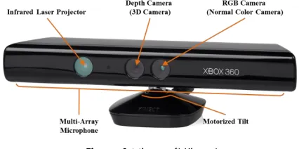
Microsoft Kinect is a 3D camera that is used to capture the 3D data [11]. Kinect has five main components: (i) RGB camera (normal color camera), (ii) depth camera (3D camera), (iii) infrared (IR) laser projector, (iv) multi-array microphone and (v) motorized tilt. All
components are shown in Figure 1. IR laser projector is used to emit infrared rays to the scene and reflected back by objects on the beam to the 3D camera. Kinect reading speed is 30Hz or 30 times per second and it has 640x480 pixels resolution for both RGB and 3D camera. This device has the ability to read a range of up to ± 9.9 m starting at a distance of ± 500 cm but with Kinect drivers supplied by Microsoft's own Kinect set can only be read between the range 1.2 - 3.5m [2]. Kinect is used because it is a low-cost and affordable 3D camera.
Figure 1 Microsoft Kinect
3.2 RGB and Depth Data
In this research, the RGB data is very important component to detect the human face as RGB color data contains information that can be used to get the current position of the face in the camera scene [12].
Depth data is also becoming an important element in getting the point cloud data for the process of forming a human face avatar. It is crucial to position in parallel with the similar images in RGB camera.
Figure 2 Shows the view of Kinect. depth data, RGB data, depth + RGB data and depth with color information (start from left)
Figure 2 show the images obtained from the RGB Kinect depth data and real data from the same scene. RGB and depth data have no similarities in terms of pixel position due to its 3D camera and the RGB camera has different position and it repaired with a little calibration of both the camera.
As illustrated in Figure 2, the depth data obtained from Kinect is not accurate and complete. This shows that the Kinect has a lack of depth determination and produce high noise data.
4.0 FACE DETECTION
The first process is done is by using face detection with Haar-like features techniques [13]. Based on this technique, it requires a RGB camera data to enable the face to be detected.
The main idea is when the position of face is detected; the visible angle of face will be displayed. To increase the speed of the source of RGB taken from Kinect, we set a specific area in the middle of the RGB camera view and also for the depth camera. We determine the size of selected RGB position is 200x200 pixels. Face detection will be done in the area alone. After a face is detected, it will be scaled down to 50x50 pixels. This directly reduces the computation cost for this process. By using a large size, it will consume more time to process the data and decrease the frame-per-second (FPS) for a direct application.
Then, the size and the position obtained from the process are sent to the point cloud data which is necessary to process data only. At the point cloud data, point cloud will limit to 100 pixels only. Figure 3 shows an area with dimension axis x, y and z. Explanation on the data acquisition steps for face detection is expressed in flowchart form as shown in Figure 4.
Figure 5 shows the extraction process done after the face is detected and then the data is sent to the size and position of point cloud data to be extracted. Diagram on the left shows the data of images captured by the camera. Blue line shows the face detection, while the yellow color is the detected face. Right-hand side of the diagram shows the data extraction. Culling process is a process of removing specific data which are not required at this time in order to save time during the rendering process [14, 15].
Figure 1 Dimension of point cloud data extraction
Figure 2 Flowchart of data acquisition for face detection
Figure 3 Extraction process. Face detection (left) and extract point cloud (right)
Figure 6 shows a top view of the difference between before and after the culling process. Based on the figure, it shows that there are a number of unnecessary data remaining in the scene and thus omission process is needed. It is facilitate the process of data during processing.
5.0 EXPERIMENTAL RESULT
We have conducted an experiment where the point cloud data is obtained for specific areas of the human face. The experimental results from the previous
processes are shown in
Figure 4. These results were automatically taken from the application and did not require any calibration. The recommended method is very easy to get the point cloud data to a human face. We use several different data to demonstrate the ability of this application to be used in the future.
The data obtained is in the form of color image data point cloud. It is easy to be manipulated and used. For point cloud data, it can be manipulated using a variety of point cloud software such as MeshLab [16].
In our experiment, the data for the face is taken from different position of face direction to allow the holes resulting from the draw down data that is not visible. These data do not seem to be causing lack of points needed to produce the best face. As a result, the data should be taken from various angles to improve the situation (refer to
Figure 5).
Regarding the data obtained, we used the ICP technique to register each image obtained and the published results were not perfect. This shows that ICP can only do registration for objects or rigid points only for the objects that have in common with each other (see
Figure 6).
The points are non-rigid points which do not have any hard data correspondence to do transformation. Therefore, the non-rigid registration is used to obtain the points of correspondence that can be used as data and this technique is also able to perform deformation of these points.
In doing the experiment for the CPD algorithm, the partial use of face point cloud as a source and target data were used but the results still do not meet the target result which is the partial point cloud of face map. But the capacity obtained by this algorithm can help this research with the number of changes that must be made to this algorithm.
Figure 4 Captured data. RGB image (left), point cloud data + color (middle) and point cloud data (right)
Our results showed that there was an occurrence between the target and source data with data similarity.
Figure 7 shows a source data and a target data which are not aligned. Using CPD techniques, the results published are as shown in Figure 10 (right side). This experiment only used 28 iterations and the time to finish the iterations is only 1.6262 seconds. This shows the CPD is able to change the specific points on the real target and was able to find the correspondence data. In this case, the use of CPD is needed to produce a quality 3D face by only using low-cost 3D camera with some fine-tunes operations to be performed.
6.0 EXPERIMENTAL RESULT
We have presented a method for producing a 3D face model by using a cheap and affordable approach for the public. Even though the Kinect technology still has some drawbacks such as having high noise data but by using appropriate methods, it can produce high quality results.
Currently, we are working on improving and extending this works to the other level. The use of non-rigid registration techniques as suggested by Li et al. [8] and Zollhöfer et al. [2] are very useful and necessary as a means to produce the quality 3D models. Smoothing techniques and mapping templates will improve the quality of the results. Reviews on head pose estimation will be used to reduce registration costs when facing with multiple point cloud data [17-19]. There are still weaknesses in the current method because we are not implementing the right face data acquisition. In this research, the improvement can be done to enhance the ability of the developer to produce a smarter product.
For future work, we are going to get any features from a face that can be extracted like eyes, mouth and nose which allows the ICP is used to shorten and simplify the registration process. The algorithm is being produced by Myronenko et al. [3] can be improved to suit with our research work.
Figure 6 Source data(left), after ICP (middle), target data (right)
Figure 7 CPD algorithm. Before registration (left) and after registration (right) [3, 4]
References
[1] Ismail, M. S. Sunar, M. K. Mohd Sidik, and C. S. Yusof. 2011. A Review of Dynamic Motion Control Considering Physics for Real Time Animation Character. Digital Media and Digital Content Management (DMDCM), 2011 Workshop on, 2011. 86-90.
[2] Zollhöfer, M., M. Martinek, G. Greiner, M. Stamminger, and J. Süßmuth. 2011. Automatic Reconstruction of Personalized Avatars from 3D Face Scans. Computer Animation and Virtual Worlds. 22: 195-202.
[3] Myronenko, X. Song, and M. A. Carreira-Perpinán. 2006. Non-rigid Point Set Registration: Coherent Point Drift.
Advances in Neural Information Processing Systems. 1009-1016.
[4] Myronenko and S. Xubo. 2010. Point Set Registration: Coherent Point Drift. Pattern Analysis and Machine Intelligence, IEEE Transactions on. 32: 2262-2275.
[5] Rahim; M. S. M., S. A. M. Isa; A. Rehman; T. Saba. 2013. Evaluation of Adaptive Subdivision Method on Mobile Device. 3D Research. 4(2): 1-10.
[6] Besl, P. J. and N. D. McKay. 1992. A Method for Registration of 3-D shapes. Pattern Analysis and Machine Intelligence, IEEE Transactions on. 14: 239-256.
[7] Weise, T., S. Bouaziz, H. Li, and M. Pauly. 2011. Realtime Performance-based Facial Animation. ACM Trans. Graph.
30: 77.
[8] Li, H., R. W. Sumner, and M. Pauly. 2008. Global Correspondence Optimization for Non-rigid Registration of Depth Scans. Proceedings of the Symposium on Geometry Processing. Copenhagen, Denmark.
[9] MorphFace. [Online]. From:
http://faces.cs.unibas.ch/bfm/main.php. [Accessed on 20 April 2012].
[10] Paysan, P., R. Knothe, B. Amberg, S. Romdhani, and T. Vetter. A 3D Face Model for Pose and Illumination Invariant Face Recognition. In Advanced Video and Signal Based Surveillance, 2009. AVSS '09. Sixth IEEE International Conference on, 2009. 296-301.
[11] Microsoft Kinect. Available: http://www.microsoft.com/en-us/kinectforwindows/.
[12] M. K. Mohd Sidik, M. S. Sunar, I. Ismail, M. K. Mokhtar, and N. Mat Jusoh. 2011. A Study on Natural Interaction for Human Body Motion Using Depth Image Data. In Digital Media and Digital Content Management (DMDCM), 2011 Workshop on. 97-102.
2001 IEEE Computer Society Conference on, 2001. I-511-I-518 vol.1.
[14] M. K. Mokhtar, M. S. Sunar, I. Mat Amin, and M. K. Mohd Sidik. 2011. Hierarchical Occlusion Queries on Driving
Simulation. Digital Media and Digital Content
Management (DMDCM), 2011 Workshop on, 2011. 30-34. [15] Sunar, M. S., T. M. Tengku Sembok, and A. Mohd Zin. 2006.
Accelerating Virtual Walkthrough with Visual Culling Techniques. In Computing & Informatics, 2006. ICOCI '06. International Conference on, 2006. 1-5.
[16] MeshLab. 2013. [Online]. From:
http://meshlab.sourceforge.net/. [Accessed on 17 Feb 2013].
[17] Fanelli, G., M. Dantone, J. Gall, A. Fossati, and L. Van Gool. 2013. Random Forests for Real Time 3d Face Analysis.
International Journal of Computer Vision. 101: 437-458. [18] Fanelli, G., J. Gall, and L. Van Gool. 2011. Real Time Head
Pose Estimation with Random Regression Forests. Computer Vision and Pattern Recognition (CVPR). 2011 IEEE Conference on, 2011. 617-624.


![Figure 7 CPD algorithm. Before registration (left) and after registration (right) [3, 4]](https://thumb-us.123doks.com/thumbv2/123dok_us/1293598.1161917/5.612.328.556.58.231/figure-cpd-algorithm-before-registration-after-registration-right.webp)
