Available online: https://edupediapublications.org/journals/index.php/IJR/ P a g e | 3881
Implementation of Low-Cost High-Performance Montgomery
Modular Multiplication
1Medepalli Narasimha Rao, 2Keerti kumar korlapati
1Asistant professor, 2Associate professor,
1,2
1,
Dept. of ECE,
Kodada institute of Technology and Science for Wombn, Kodada, Telangana 2.
Vaageswari College of Engineering, karimnagar, Telangana.
Abstract: In this we are introducing a
simple and efficient Montgomery multiplication algorithm such that the low-cost and high-performance Montgomery modular multiplier can be implemented accordingly. The proposed multiplier receives and outputs the data with binary representation and uses only one-level carry-save adder (CSA) to avoid the carry propagation at each addition operation. To overcome the weakness of the one level CSA(more clock cycles), a configurable CSA (CCSA), which could be one full-adder or two serial half-full-adders, is proposed to reduce the extra clock cycles for operand pre computation and format conversion by half. In addition, a mechanism that can detect and skip the unnecessary carry-save addition operations in the one-level CCSA architecture while maintaining the short critical path delay is developed. As a result, the extra clock cycles for operand pre computation and format conversion can be hidden and high throughput can be obtained. Experimental results show that the proposed Montgomery modular multiplier can achieve higher performance and significant area–time product improvement when compared with previous designs.
Key words: Carry-save addition,
Montgomery modular multiplier, public-key cryptosystem.
I.INTRODUCTION
Available online: https://edupediapublications.org/journals/index.php/IJR/ P a g e | 3882 representation of input and output
operands, these approaches can be roughly divided into semi-carry-save (SCS) strategy and full carry-save (FCS) strategy.
Fig. 1. MM algorithm.
In the SCS strategy [5]–[8], the input and output operands (i.e., A, B, N, and S) of the Montgomery MM are represented in binary, but intermediate results of shifting modular additions are kept in the carry-save format to avoid the carry propagation. However, the format conversion from the carry-save format of the final modular product into its binary representation is needed at the end of each MM. This conversion can be accomplished by an extra carry propagation adder (CPA) [5] or reusing the carry-save adder (CSA) architecture [8] iteratively. Contrary to the SCS strategy, the FCS strategy [9], [10] maintains the input and output operands A, B, and S in the carry-save format, denoted as (AS, AC), (BS, BC), and (SS, SC), respectively, to avoid the format conversion, leading to fewer clock cycles for completing a MM. Nevertheless, this strategy implies that the number of operands will increase and that more CSAs and registers for dealing with these operands are required. Therefore, the FCS-based Montgomery modular multipliers possibly have higher hardware complexity
and longer critical path than the SCS-based multipliers.
Available online: https://edupediapublications.org/journals/index.php/IJR/ P a g e | 3883 reduced. As a result, the proposed
Montgomery multiplier can obtain higher throughput and much smaller area-time product (ATP) than previous Montgomery multipliers.
II.LITERATURE SURVEY
A. Montgomery Multiplication
Fig. 1 shows the radix-2 version of the Montgomery MM algorithm (denoted as MM algorithm). As mentioned earlier, the Montgomery modular product S of A and B can be obtained as S = A × B × R−1 (mod N), where R−1 is the inverse of R modulo N. That is, R × R−1 = 1 (mod N). Note that, the notation Xi in Fig. 1 shows the i th bit of X in binary representation. In addition, the notation Xi: j indicates a segment of X from the i th bit to j th bit. Since the convergence range of S in MM algorithm is 0 ≤ S < 2N, an additional operation S = S − N is required to remove the oversize residue if S ≥ N. To eliminate the final comparison and subtraction in step 6 of Fig. 1, Walter [22] changed the number of iterations and the value of R to k + 2 and 2k+2 mod N, respectively. Nevertheless, the long carry propagation for the very large operand addition still restricts the performance of MM algorithm.
In this section, we propose a new SCS-based Montgomery MM algorithm to reduce the critical path delay of Montgomery multiplier. In addition, the drawback of more clock cycles for completing one multiplication is also improved while maintaining the
advantages of short critical path delay and low hardware complexity.
B. Critical Path Delay Reduction
Available online: https://edupediapublications.org/journals/index.php/IJR/ P a g e | 3884 (a)
(b)
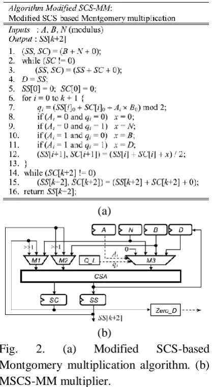
Fig. 2. (a) Modified SCS-based Montgomery multiplication algorithm. (b) MSCS-MM multiplier.
Furthermore, the extra clock cycles for performing B+N and the format conversion through repeatedly executing the carry-save addition (SS, SC) = SS+SC+0 are dependent on the longest carry propagation chain in SS + SC. If SS = 111…1112 and SC = 000…0012, the one-level CSA architecture needs k clock cycles to complete SS + SC.
That is, ∼3k clock cycles in the worst case are required for completing one MM. Thus, it is critical to reduce the required clock cycles of the MSCS-MM multiplier.
B. Clock Cycle Number Reduction
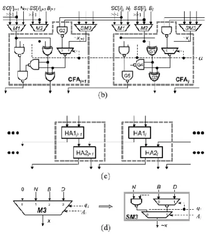
To decrease the clock cycle number, a CCSA architecture which can perform one three-input carry-save addition or two serial two-input carry-save additions is proposed to substitute for the one-level CSA architecture in Fig. 2(b). Fig. 3(a) shows two cells of the one-level CSA architecture in Fig. 2(b), each cell is one conventional FA which can perform the three-input carry-save addition. Fig. 3(b) shows two cells of the proposed configurable FA (CFA) circuit. If α = 1, CFA is one FA and can perform one three-input carry-save addition (denoted as 1F_CSA). Otherwise, it is two half-adders (HAs) and can perform two serial two-input carry-save additions (denoted as 2H_CSA), as shown in Fig. 3(c). In this case, G1 of CFAj and G2 of CFAj+1 in Fig. 3(b) will act as HA1 j in Fig. 3(c), and G3, G4, and G5 of CFAj in Fig. 3(b) will behave as HA2j in Fig. 3(c).Moreover, we modify the 4-to-1 multiplexer M3 in Fig. 2(b) into a simplified multiplier SM3 as shown in Fig. 3(d) because one of its inputs is zero, where ∼ denotes the INVERT operation. Note that M3 has been replaced by SM3 in the proposed one-level CCSA architecture shown in Fig. 3(b). According to the delay ratio, TSM3 (i.e., 0.68 × TFA) is approximate to TMUX3 (i.e., 0.63 × TFA) and TMUXI2 (i.e., 0.23 × TFA) is smaller than TXOR2 (i.e., 0.34×TFA).
Available online: https://edupediapublications.org/journals/index.php/IJR/ P a g e | 3885 Fig. 3. (a) Conventional FA circuit. (b)
Proposed CFA circuit. (c) Two serial HAs. (d) Simplified multiplexer SM3.
Therefore, the critical path delay of the proposed one-level CCSA architecture in Fig. 3(b) is approximate to that of the one-level CSA architecture in Fig. 3(a). As a result, steps 3 and 15 of Fig. 2(a) can be replaced with (SS, SC) = 2H_CSA (SS, SC) and (SS [k + 2], SC [k + 2]) = 2H_CSA (SS[k +2], SC[k +2]) to reduce the required clock cycles by approximately a factor of two while maintaining a short critical path delay. In addition, we also skip the unnecessary operations in the for loop (steps 6 to 13) of Fig. 2(a) to further decrease the clock cycles for completing one Montgomery MM. The crucial computation in the for loop of Fig. 2(a) is performing the following three-to-two carry-save addition:
III.PROPOSED SYSTEM
On the bases of critical path delay reduction, clock cycle number reduction,
Available online: https://edupediapublications.org/journals/index.php/IJR/ P a g e | 3886 SM3, one skip detector Skip_D, one zero
detector Zero_D, and six registers. Skip_D is developed to generate skipi+1, ˆ q, and ˆA in the i th iteration. Both M4 and M5 in Fig. 5 are 3-bit 2-to-1 multiplexers and they are much smaller than k-bit multiplexers M1, M2, and SM3. In addition, the area of Skip_D is negligible when compared with that of the k-bit one-level CCSA architecture. The select signals of multiplexers M1 and M2 in Fig. 11 are generated by the control part, which are not depicted for the sake of simplicity.
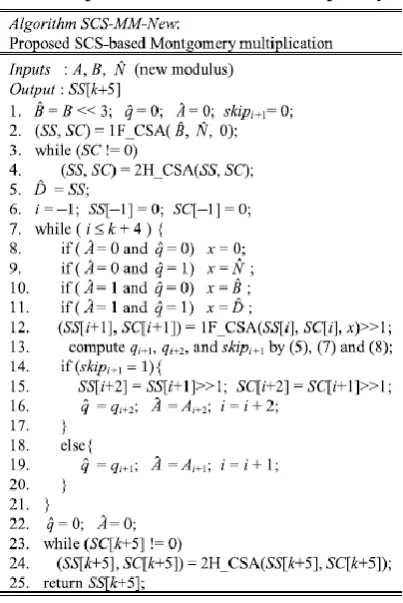
Fig. 4. SCS-MM-New algorithm.
At the beginning of Montgomery multiplication, the FFs stored skipi+1, ˆ q, ˆA are first reset to 0 as shown in step 1 of SCS-MM-New algorithm so that ˆD = ˆB + ˆN can be computed via the one-level CCSA architecture.
Fig.5. SCS-MM-New multiplier.
When performing the while loop, the skip detector Skip_D shown in Fig. 6 is used to produce skipi+1, ˆ q, and ˆA. The Skip_D is composed of four XOR gates, three AND neither gates, one NOR gate, and two 2-to-1 multiplexers. It first generates the qi+1, qi+2, and skipi+1 signal in the i th iteration according to (5), (7), and (8), respectively, and then selects the correct ˆ q and ˆA according to skipi+1.
Available online: https://edupediapublications.org/journals/index.php/IJR/ P a g e | 3887 New algorithm are performed together in
the next clock cycle of iteration i. In addition, M4 and M5 also select and output the correct SC[i ]2:0 and SS[i ]2:0 according to skipi+1 generated in the i th iteration. Note that SC[i ]2:0 and SS[i ]2:0 can also be obtained from M1 and M2 but a longer delay is required because they are 4-to-1 multiplexers. After the while loop in steps 7–21 is completed, ˆ q and ˆA stored in FFs are reset to 0. Then, the format conversion in steps 23 and 24 can be performed by the SCS-MM-New multiplier similar to the computation of ˆD = ˆB + ˆN in steps 3 and 4. Finally, SS [k +5] in binary format is outputted when SC[k + 5] is equal to 0.
IV.CONCLUSION
FCS-based multipliers maintain the input and output operands of the Montgomery MM in the carry-save format to escape from the format conversion, leading to fewer clock cycles but larger area than SCS-based multiplier. To enhance the performance of Montgomery MM while maintaining the low hardware complexity, this paper has modified the SCS-based Montgomery multiplication algorithm and proposed a low-cost and high-performance Montgomery modular multiplier. The proposed multiplier used one-level CCSA architecture and skipped the unnecessary carry-save addition operations to largely reduce the critical path delay and required clock cycles for completing one MM operation. Experimental results showed that the proposed approaches are indeed capable of enhancing the performance of radix-2
CSA-based Montgomery multiplier while maintaining low hardware complexity.
V.REFERENCES
[1] R. L. Rivest, A. Shamir, and L. Adleman, “A method for obtaining digital signatures and public-key cryptosystems,” Commun. ACM, vol. 21, no. 2, pp. 120– 126, Feb. 1978.
[2] V. S. Miller, “Use of elliptic curves in cryptography,” in Advances in Cryptology. Berlin, Germany: Springer-Verlag, 1986, pp. 417–426.
[3] N. Koblitz, “Elliptic curve cryptosystems,” Math. Comput., vol. 48, no. 177, pp. 203–209, 1987.
[4] P. L. Montgomery, “Modular multiplication without trial division,” Math. Comput., vol. 44, no. 170, pp. 519– 521, Apr. 1985.
[5] Y. S. Kim, W. S. Kang, and J. R. Choi, “Asynchronous implementation of 1024-bit modular processor for RSA cryptosystem,” in Proc. 2nd IEEE Asia-Pacific Conf. ASIC, Aug. 2000, pp. 187– 190.
[6] V. Bunimov, M. Schimmler, and B. Tolg, “A complexity-effective version of Montgomery’s algorihm,” in Proc. Workshop Complex. Effective Designs, May 2002.
[7] H. Zhengbing, R. M. Al Shboul, and V. P. Shirochin, “An efficient architecture of 1024-bits cryptoprocessor for RSA cryptosystem based on modified Montgomery’s algorithm,” in Proc. 4th IEEE Int. Workshop Intell. Data Acquisition Adv. Comput. Syst., Sep. 2007, pp. 643–646.
Available online: https://edupediapublications.org/journals/index.php/IJR/ P a g e | 3888 Microprocessors Microsyst., vol. 31, no. 7,
pp. 456–459, Nov. 2007.
[9] C. McIvor, M. McLoone, and J. V. McCanny, “Modified Montgomery modular multiplication and RSA exponentiation techniques,” IEE Proc.- Comput. Digit. Techn., vol. 151, no. 6, pp. 402–408, Nov. 2004.