Semicircle CSRR with Circular Slot Array Structures for High Level
Mutual Coupling Reduction in MIMO Antenna
Arunachalam Ambika1, 2, * and Chandrapragasam Tharini1, 2
Abstract—A single semicircle shape Complementary Split Ring Resonator (CSRR) is designed to enhance isolation by suppressing mutual coupling between MIMO antennas. Furthermore, high level of mutual coupling by introducing circular slot in-between patch antennas on a substrate which creates additional coupling path between the patch antennas also opposes the some leakage signals coming back from the opposite coupling path after CSRR is etched from ground plane. The proposed patch antenna dimensions are chosen as 37.26×28.13 mm for operating at 2.51 GHz frequency, and the low-cost dielectric material, FR-4 (εr = 4.4), is chosen as the dielectric substrate with 1.6 mm height. TheS parameters of proposed antenna prototype are characterized by using VNA. The measured return loss (S11) and isolation (S21) are −23.13 dB &−56.8 dB, respectively. The results show that by introducing
semicircle CSRR and circular slot, the structure provides a 33.2 dB improvement in mutual coupling for MIMO antenna. Hence, the proposed structure provides a better isolation between two antennas without affecting antenna performance.
1. INTRODUCTION
A microstrip patch antenna mounted on a dielectric substrate with the substrate backed by metallic ground is widely used for many wireless applications because of is structure and easy fabrication [1]. When placing two patch antennas close to each other, near field of each antenna is much disturbed so that the mutual coupling takes place between the two patch antennas. The mutual coupling changes the radiation pattern, gain, and also input impedance of the individual antenna elements in an array. Coupling arises due to two reasons, free space radiation [3] and surface wave effects [4]. The surface wave power diffracts from the edges of the substrate, resulting in a disturbance of the radiation pattern. Various methods have been introduced for decoupling between antennas. By using metamaterial structures [2, 5, 11] and using CSRR and SRR, various techniques have been introduced to improve isolation; they are decoupled networks [6], parasitic elements [7], defected ground structures [8], and neutralization lines [9]. Comparing SRR and CSRR techniques, CSRR reduces more coupling between antennas. CSRR and SRR have the same resonating frequency [10], so CSRR can be directly derived from SRR, and the magnetic properties can be interchanged from the CSRR technique. Hence the proposed CSRR is very useful for suppressing the coupling between antennas. The significant advantage of using this semicircle shape CSRR and circle slot together makes antennas have compact size, easy fabrication, and high filtering capability useful for coupling suppression.
Received 10 September 2019, Accepted 19 November 2019, Scheduled 29 November 2019
* Corresponding author: Arunachalam Ambika ([email protected]).
1 Department of Electronics and Communication, B.S. Abdur Rahman Crescent Institute of Science And Technology, Chennai,
24 Ambika and Tharini
2. DESIGN OF PROPOSED SINGLE CELL SEMICIRCLE CSRR STRUCTURE
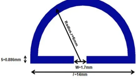
The single unit cell of semicircle Complementary Split Ring Resonator structure (CSRR) is considered for enhancing isolation in closely spaced antennas. The frequency design calculation is carried out using Equations (1) and (2) such that this frequency is the same as antenna resonant frequency to reduce the coupled signal. The structure is designed using High-Frequency Structural Simulator (HFSS), which is shown in Figure 1.
Figure 1. Semi-circle CSRR structure.
Table 1. Optimized dimension of semicircle CSRR.
Parameters Dimensions(mm)
Radius,r 6
Strip width, w 1.7
Thickness of ring, s 0.886 Outer ring length,l 14
The total length of the semicircle CSRR is calculated as
L=πr+l=w= 2s (1)
wherer,l,w,s are radius, outer length, width of the strip, thickness of strip, respectively
f0 = c
2L√εeff
(2)
wherec = speed of light, L = total length of CSRR,εeff = effective permeability.
The optimized dimension of the semi-circle CSRR is given in Table 1. First, the single CSRR structure is analyzed in the unit cell wave analyzer, shown in Figure 2. The perfect magnetic conductor (PMC) walls and perfect electric conductor (PEC) walls are defined at the top and bottom of the waveguide, and the remaining two walls are utilized for port excitation. Inside air-filled waveguide, the proposed structure is kept on an FR4 dielectric substrate. The real and imaginary parts ofS11,S21are
determined for the operating frequency of 2.51 GHz from the waveguide analysis. From the extraction of S parameters, the negative permeability is calculated by the following equations [12].
n = 1 kdcos
−1
1 2S21
1−S112 −S212
(3)
z =
(1 +S11)2−S212
(1 =S11)2−S212
(4)
Figure 2. Waveguide unit cell with semicircle CSRR structure.
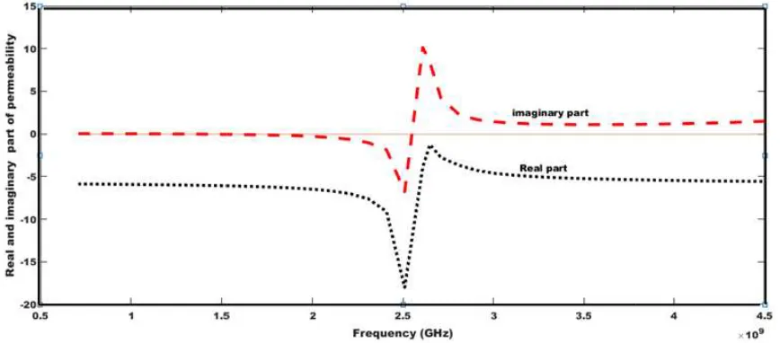
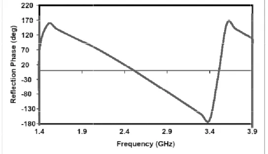
The stopband frequency behavior of CSRR is proven by using Equation (5), and the negative permeability, μ, is calculated by using Equations (3) & (4) and its negative permeability and phase response are plotted in Figures 3 & 4. Generally, the left-handed material has a negative refractive index with either negative permittivity or negative permeability which alters the propagation of the electromagnetic wave. The dispersion relation of left-handed transmission lines gives relation between the phase constant and frequency by Equation (6).
n= c v =
cβ
ω (6)
where propagation constant of a material is defined as
β=ω(με)12 (7)
It is observed from Figure 3 that the real part of permeability (μ) shows negative value of −18.5 at the operating frequency 2.51 GHz. By using this property, the mutual coupling effect can be highly reduced for closely spaced two-element antennas. In general, a closely spaced antenna generates more scatter surface waves in between them. Because of this surface wave, the overall performance of the antenna
26 Ambika and Tharini
Figure 4. Phase reflection of semicircle CSRR unit cell graph.
gets degraded. To reduce the coupling effect, a CSRR structure is used. The gap in CSRR acts as the capacitance; the lines act as inductance; together they form a resonator circuit which observes the scattered signal from both sides.
3. DESIGN CONFIGURATION OF ANTENNA STRUCTURE WITH PROPOSED CSRR & CIRCULAR SLOT
In this design, the two patch antennas with a similar dimension of (37.26 mm × 28.13 mm) and inset feed are kept very close to each other at a distance of 0.059λon the top of an FR4 substrate operating in the frequency of 2.51 GHz. The designed patch antenna is shown in Figure 5.
Figure 5. Proposed MIMO antenna. Figure 6. The transmission coefficient (S21) of
single semicircle CSRR structure.
The array of proposed semi-circle CSRR array is aligned back to back and etched from the ground plane for mutual coupling suppression in the resonating frequency, which is shown in Figure 6.
In Figure 7, the comparison of various numbers of semicircle CSRR’s mutual coupling effects on the proposed antenna is presented. The enhanced isolation is obtained as 38 dB at the resonance frequency (2.51 GHz) for a 5-element semicircle CSRR array.
Compared to Figure 7, the mutual coupling suppression (S21 = −38 dB) is insufficient for Wi-Fi
Figure 7. Comparison of number of semicircle CSRR structure.
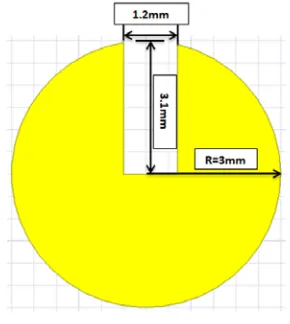
Figure 8. Circular slot structure.
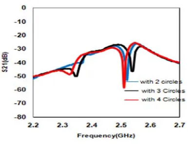
For creating a circular slot, a metal sheet is created on the substrate in-between the patch antenna, from which the circular slot structure is etched from the metal sheet. The slot and CSRR structures tend to couple with each other. The number of circular slots along with semicircular CSRR performance is analyzed at the resonance frequency (shown in Figure 9).
(a) (b)
Figure 9. (a) Antenna with CSRR and with circulator slot structure. (b) Antenna without CSRR and with circulator slot structure.
The circle slot with and without CSRR is analyzed, and the result is presented in Figure 10. The result shows that the structure with circle slot and CSRR provides an effective reduction of the mutual coupling effect between the antennas compared to that without circle slot and with CSRR.
By changing designed values of the width of the designed CSRR structure, both the circular slot and CSRR structure get coupled to the desired operating frequency. If we increase the width of the CSRR, the entire frequency range shifts towards left with the increase in the gain value. If we decrease the width of the CSRR, the entire frequency range shifts towards the right with the decrease in the gain value. By optimizing the value of the width of the CSRR as 0.886 mm, high mutual coupling suppression is achieved in the required 2.51 GHz operating frequency.
The simulated S11 and S12 parameters of the proposed antenna are shown in Figure 11. The
28 Ambika and Tharini
Figure 10. Frequency response of various circle slots.
Figure 11. Simulated frequency response of with and without CSRR & circular slot.
is found that S12 performance is improved to−58.36 dB. The improvement of isolation about 41.26 dB
can be observed by introducing CSRR.
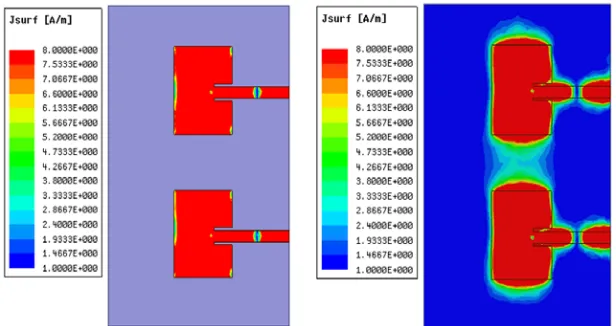
From Figure 12(a) it is shown that maximum amount of surface current flows into port 2 antenna without CSRR and circular slot. The surface current is reduced by an array of CSRR pairs between the patches, which avoids the current flow from one antenna to another. With the help of a circular slot and with CSRRs, the leakage current is further reduced between the patch antennas.
4. FABRICATED ANTENNA
The simulated antenna fabricated on low-cost FR-4 dielectric material, and the 50 Ω connector is fed in both antenna ports which is shown in Figure 13(a) (front and back views), and all S parameters are with and without semicircle CSRR and circular slot using a vector network analyzer (VNA) shown in Figure 13(b).
The results of measured and simulated S11and S21 agree with each other. In Figure 14, measured
S11&S21results with and without CSRR & circular slot are presented, andS21response of the proposed
structure shows 33.2 dB more than the conventional structure. The simulated and measuredS11 &S21
results are listed in Table 2.
(a) Without CSRR and circle slot current distribution on top and bottom surface
(b) With CSRR and without circle slot current distribution on top and bottom surface
(c) With CSRR and with circle slot current distribution on top and bottom surface
30 Ambika and Tharini
(a) (b)
Figure 13. (a) Fabricated antenna front and back view. (b) Measurement setup of VNA (with & without CSRR & circle slots).
Figure 14. MeasuredS parameters with and without CSRR & circle slot.
Table 2. Simulated and measured S parameters.
Simulated/measured Parameter Frequency (GHz) dB
Simulated S11 2.51 −17.44
S12 2.51 −58.36
Measured S11 2.415 −15.13
S12 2.415 −56.88
Envelope correlation coefficient,
(ECC) = |S
∗
11S12+S21∗ S22|
1− |S11|2− |S21|2 1− |S22|2− |S12|2
(8)
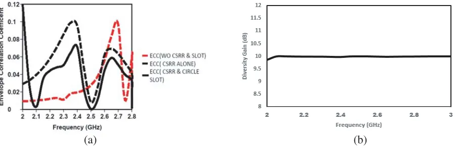
Figure 15(a) shows the variation of envelope correlation coefficient with frequency without, with CSRR & combination of both CSRR and circular slot. The ECC should have zero value in an ideal case. From the plot the proposed MIMO antenna has ECC value 0.005 which is close to an ideal value. The Diversity Gain (DG) is another important parameter, which describes the MIMO antenna performance.
The DG can be determined utilizing the formula below
DG= 10
1−(ECC)2 (9)
(a) (b)
Figure 15. (a) Envelope correlation coefficient of proposed MIMO antenna (with and without CSRR & slot and with CSRR alone). (b) Diversity gain of proposed MIMO antenna.
(a) (b)
Figure 16. (a) Radiation pattern of conventional and proposed MIMO antenna at phi = 90. (b). Radiation pattern of conventional and proposed MIMO antenna at phi = 0.
Figures 16(a) and 16(b) show the radiation pattern in both the planes (phi = 90◦, phi = 0◦) of the conventional and proposed MIMO antenna at 2.51 GHz. Due to CSRR etched on the ground planes, slight backward radiation occurs other than that the radiation pattern of proposed MIMO antenna is not much disturbed.
5. COMPARISON
The high level of mutual coupling of proposed antenna structure is compared with existing methods which is presented in Table 3.
Table 3. Comparison of mutual coupling of proposed antenna with existing antennas.
Reference Frequency in GHz Methods Used for reducing mutual coupling Improvement in dB
[9] 2.55 E Shaped Electronic Band Gap (EBG) structure 26
[10] 2.55 Multi Layered EBG 31
[11] 2.4 3 D Novel Meta material 18
32 Ambika and Tharini
6. CONCLUSION
Design, implementation, and single-cell analysis of a semicircle CSRR are presented. The negative permeability of the CSRR is analyzed at the operating frequency. The array of the semicircle CSRR is analyzed with a closely spaced patch antenna (f = 2.51 GHz) at the ground surface in-between patch antennas. It enhances isolation to nearly 38 dB. Further improvement is carried out by including a circular slot in existing structures. The entire design is fabricated on FR4 material. The return loss and transmission coefficients are measured and compared with simulated results. The proposed semicircle CSRR with circular slot method is utilized for high mutual coupling suppression in closely spaced (0.059λ) patch antennas for Wi-Fi application with 0.005 Envelope Correlation Coefficient and 10 dB directive gain. The Simple and low cost material makes the proposed antenna suit for Wi-Fi antenna performance enhancement.
REFERENCES
1. Sahandabadi, S. and S. V. A. Makki, “Mutual coupling reduction using complementary of SRR with wire MNG structure,”Microwave Optical Technology Letters, 1–4, 2019.
2. Kumar, N. and U. K. Kommuri, “MIMO antenna H-plane isolation enhancement using UC-EBG structure and metalline strip for WLAN applications,”Radio Engineering, Vol. 28, No. 2, 399–406, June 2019.
3. Panda, P. K. and D. Ghosh, “Isolation enhancement of patch antennas using metamaterial substrate,”IEEE International Symposium on Antennas and Propagation&USNC/URSI National Radio Science Meeting, 2017.
4. Malathi, C. J. and D. Thiripurasundari, “Review on isolation techniques in MIMO antenna,”Indian Journal of Science and Technology, Vol. 9, No. 35[2], 2016.
5. Mori, K., K. Uchida, and H. Arai, (n.d.), “Active antenna using parasitic elements,”IEEE Antennas and Propagation Society and International Symposium, Vol. 3, 1636–1639, 2002.
6. Zulkifli, F. Y. and E. T. Rahardjo, and D. Hartanto, “Mutual coupling reduction using dumbbell defected ground structure for multiband microstrip antenna array,” Progress In Electromagnetics Research Letters, Vol. 13, 29–40, 2010.
7. Su, S.-W., C.-T. Le, and F.-S. Chang, “Printed MIMO-antenna system using neutralization-line technique for wireless USB-dongle applications,”IEEE Transitions on Antennas and Propagation, Vol. 60, No. 2, 2011.
8. Selvaraju, R. R., M. H. Jamaluddin, M. R. Kamaruddin, J. Nasir, and M. H. Dahri, “Enhance isolation and pattern error correction in a 5G beamforming linear array using CSRR,”IEEE Access, Vol. 6, 65922–65934, 2018.
9. Jiang, T., T. Jiao, and Y. Li , “Array enhance isolation using L-loading E-shape electromagnetic band gap structures,” Hindawi Publishing Corporation International Journalof Antennas and Propagation, Vol. 2016, 13 July 2016.
10. Jiang, T., T. Jiao, and Y. Li, “A low mutual coupling MIMO antenna using periodic multi-layered electromagnetic band gap structures,”ACES Journal, Vol. 33, No. 3, March 2018.
11. Li, Y. and X. Liu, “Enhance isolation of a MIMO antenna array using 3-D novel meta-material structures,”Article in Applied Computational Electromagnetics Society Journal, August 2018. 12. Smith, D. R., D. C. Vier, T. Koschny, and C. M. Soukoulis, “Electromagnetic parameter retrieval