Microfluidic Reconfigurable Filter Based on Ring Resonators
Tejinder Kaur1, Leider Osorio1, Jose L. Olvera-Cervantes2, Roberto Reyes-Ayona1, and Alonso Corona-Chavez2, *
Abstract—In this letter a novel microfluidic reconfigurable filter is presented at 1, 1.4 and 1.8 GHz. This triple band filter is based on dual-mode ring resonators where metal-liquid switches are used for interconnection of different resonators and feed lines, therefore, allowing tuning of its center frequency as well as of its external Q. Simulated and experimental results are shown with good agreement.
1. INTRODUCTION
Modern communication systems require miniaturized RF filters with high performance. In order to meet the challenging multifrequency capabilities of these communication systems, adaptive and reconfigurable RF filters are a way forward [1–3]. However, current technologies face challenges such as linearity (as it is the case for solid state devices) and reliability as it is the case for MEMS filters [4, 5].
One technology that promises to overcome these shortcomings is microfluidic liquid metal filters such as the ones mentioned in [6–9]. In [10–12] SIW filters are presented with liquid metal tunability. In [13], eutectic Gallium-Indium is used to reconfigure a microstrip hairpin-based band-pass filter with a 60% tuning range. In [14] a microstrip reconfigurable comb-line filter is shown at 7 different bands. However, in none of these filters, the external Q can be independently tuned. Therefore, as frequency increases, the resonator couplings increase at a higher rate than the external Q, giving large ripples at higher frequencies.
In this letter we present a novel liquid metal reconfigurable filter based on dual band square ring resonators. The structure operates at 3 bands (1 GHz, 1.4 GHz and 1.8 GHz). Eutectic Gallium-Indium based switches are used to shift to different frequencies, where different resonator and feed line pads can be interconnected. The advantage of this configuration is that it allows independent external Q tuning, which is achieved by switching different tap coupling feed lines. This structure is realized in Rogers UL2000 with εr = 2.5 and h= 0.762 mm. For the liquid metal switches micropumps are used. Sodium hydroxide was used to improve the liquid metal fluidity. Table 1 shows a comparison between our proposal and the available literature.
2. FILTER DESIGN
The design starts with three conventional square ring resonators centered at 1 GHz, 1.4 GHz and 1.8 GHz, as shown in Figure 1(a), whereLi is given by Eq. (1)
Li = 300
f(GHz)√εr = mm (1)
Received 4 August 2018, Accepted 25 September 2018, Scheduled 12 October 2018
* Corresponding author: Alonso Corona-Chavez ([email protected]).
Reference [13] [6] [14] [10] [12] This work
Resonator type Hairpin WG λ/2 SIW SIW Ring
Operational frecuency (GHz) 0.8–1.5 NA 1.5–4 NA 2.2–2.5 1–1.8
Response type BP BR-BP BP BP BP BP
External Q tuning No No No No No Yes
where f is the central frequency, and εr is the effective permittivity. At each frequency we obtain
L1 = 50 mm, L2= 35 mm and L3 = 27 mm, with a linewidth ofW = 2.5 mm.
The filters are chosen to have a 15% fractional bandwidth (FBW) with a 2-pole Chebyshev response. The low pass coefficients g are g0 = 1, g1 = 0.8431, g2 = 0.6220 and g3 = 1.3554. From these values,
the externalQex and mutual coupling coefficients can be calculated using Equations (2) and (3) [15].
Qext = g0g1
F BW (2)
kj·j+1 = F BW √
g1g2
(3)
The final values are Qext= 5.6 and k12 = 0.21.
In order to build the triple band miniaturized filter, the double band ring resonators with a notch are placed inside one another as shown in Figure 1(b), where meandering is performed accordingly. Tap coupling is utilized. As seen from Figure 1(b), 8 gaps are left inside the resonators and coupling lines. In these gaps, liquid metal switches will be placed to reconfigure the desire band.
To extract the external coupling coefficients, a full wave simulator is utilized, using the technique described in [15]. For the 1 GHz filter, three tap couplings are used as seen in Figure 1. The gaps
S1, S2, S3, S4 and S1a are connected with transmission lines, and the rest are left unconnected. The
opposite side of the circuit is weakly-coupled, and the notch is removed. To obtainQextwe use Equation (4). t2 is kept constant to 0 mm, and we vary t1 (see Figure 2). For our required value of Qext= 5.62
we obtain t1 = 3.5 mm.
Qex = fo Δf3 dB
(4)
k12 =
(f2)2−(f1)2
(f2)2+ (f1)2
(5)
(a) (b)
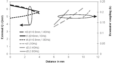
Figure 2. Simulated results of external coupling (Qext) and resonator coupling (k) at various distances (t3, t1, t4, d1, d2 and d3).
wherefo is the resonant frequency; Δf3 dB is the 3 dB bandwidth;f1andf2 are the resonant frequencies
of the coupled resonators.
For the 1.4 GHz filter,S1, S3, S5, S6 and S1a are connected and the rest unconnected. In this case,
we fixt1 = 3.5 mm and changet3 (Figure 2). Our required value is t3= 3.5 mm.
For the 1.8 GHz filter,S7,S8andS1bare connected and the rest unconnected. By fixingt1= 3.5 mm
and changingt4, we obtain t4 = 4 mm (Figure 2).
To obtain the coupling coefficientkof the dual band resonator, the notch size (d) is optimized using a full wave simulator. The structure is weakly coupled at both ends. For the 1 GHz filter,S1, S2, S3 and S4 are connected (the rest left unconnected). Using the simulator, the distanced1 is changed and thek
extracted using Equation (5). For 1.4 GHz S1, S3, S5 and S6 are connected, and for 1.8 GHz S7 and S8
are connected leaving the rest unconnected. Figure 2 shows the extracted values giving d1 = 11.2 mm, d2 = 9.5 mm and d3 = 8 mm.
It is seen that the 1 GHz resonator presents a harmonic resonance at 1.7 GHz, therefore interfering with our third passband. For this reason, a resonant suppression open stub of length L was added to the structure (Figure 1). This stub is designed to be λ/4 at 1.7 GHz; hence, forcing a virtual short on the outer resonator and attenuating the undesired resonance. The length of the stub was optimized, and the final dimension isL= 19 mm.
3. SIMULATED AND EXPERIMENTAL RESULTS
The final structure (Figure 1(b)) was simulated with the respective connections for each band (Table 1). The circuit was constructed using conventional photolithography on a Rogers UL2000 substrate with
h = 0.762 mm. To implement the metal liquid switches, thin pipes of 2.5 mm diameter are connected to syringes where Gallium/Indium eutectic is made to flow. It is important to note that pipes should be thin enough to have little impact on the filter response. For our case, liquid metal thickness is about 1.5 mm, which did not cause any apparent filter response degradation. To achieve proper flow, the metal liquid is mixed with a small amount of sodium hydroxide [10]. Switches are shown in Figure 3(b), where a dielectric capsule is placed on the desired transmission lines. When an ON connection is needed, metal liquid is pumped through, hence, connecting the lines. A picture of the final circuit with all the switches and manual pumps is shown in Figure 3. The switching for all the bands is shown in Table 2.
(a) (b)
Figure 3. (a) Picture of fabricated filter; (b) Filter setup showing a schematic of metal switch and a picture of the final experimental setup with syringes used as micropumps.
Frequency (GHz) Frequency (GHz)
(a) (b)
Figure 4. Simulated and experimental responses corresponding to: (a) Return Losses, and (b) Insertion Losses.
Table 2. Switching for triple band filter.
f (GHz) S1 S2 S3 S4 S5 S6 S7 S8 S1a S2a S3a S4a S1b S1c
1 On On On On On On On On
1.4 On On On On On On
1.8 On On On On
insertion losses are 0.68 dB for the first band, 0.69 dB for the second band and 0.47 dB for the third band.
4. CONCLUSIONS
REFERENCES
1. Hossain, E. and M. Hasan, “5G cellular: Key enabling technologies and research challenges,” IEEE
Instrum. Meas. Mag., Vol. 18, No. 3, 11–21, 2015.
2. Rais-Zadeh, M., et al., “Reconfigurable radios: A possible solution to reduce entry costs in wireless phones,”Proc. IEEE, Vol. 103, No. 3, 438–451, 2015.
3. Bage, A. and S. Das, “A frequency reconfigurable dual pole dual band bandpass filter for X-band applications,” Progress In Electromagnetics Research Letters, Vol. 66, 53–58, 2017.
4. El-Tanani M. A. and G. M. Rebeiz, “High-performance 1.5–2.5-GHz RF-MEMS tunable filters for wireless applications,” IEEE Trans. Microw. Theory Tech., Vol. 58, No. 6, 1629–1637, 2010. 5. Reines, I., S. J. Park, and G. M. Rebeiz, “Compact low-loss tunable X-band bandstop filter with
miniature RF-MEMS switches,” IEEE Trans. Microw. Theory Tech., Vol. 58, No. 7, Part 1, 1887– 1895, 2010.
6. Vahabisani, N., S. Khan, and M. Daneshmand, “Microfluidically reconfigurable rectangular waveguide filter using liquid metal posts,” IEEE Microwave and Wireless Components Letters, Vol. 26, No. 10, 801-3, Oct. 2016.
7. Entesari, K. and A. P. Saghati, “Fluidics in microwave components,” IEEE Microwave Magazine, Vol. 17, 50–75, May 6, 2016.
8. Arbelaez-Nieto, A., et al., “Balanced liquid metal reconfigurable microstrip filter,” Journal of
Electromagnetic Waves and Applications, Vol. 31, No. 14, 1453–1466, 2017.
9. Guo, S., et al., “A tunable low-pass filter using a liquid-metal reconfigurable periodic defected ground structure,”IEEE MTT-S Int. Microw. Symp. Dig., 10–12, 2012.
10. McClung, S. N., S. Saeedi, and H. H. Sigmarsson, “Band-reconfigurable filter with liquid metal actuation,”IEEE Trans. Microw. Theory Tech., Vol. 66, No. 6, 3073-80, Jun. 2018.
11. Dang, J. H., R. C. Gough, A. M. Morishita, A. T. Ohta, and W. A. Shiroma, “A tunable x-band substrate integrated waveguide cavity filter using reconfigurable liquid-metal perturbing posts,”
2015 IEEE MTT-S Int. Microw. Symp. IMS 2015, 1–4, 2015.
12. Eom, S., M. U. Memon, and S. Lim, “Frequency-switchable microfluidic CSRR-loaded QMSIW band-pass filter using a liquid metal alloy,” Sensors, Vol. 17, No. 4, 699, Mar. 28, 2017.
13. Palomo, T. and G. Mumcu, “Microfluidically reconfigurable metallized plate loaded frequency-agile RF bandpass filters,”IEEE Trans. Microw. Theory Tech., Vol. 64, No. 1, 158-65, Jan. 2016. 14. Palomo, T. and G. Mumcu, “Microfluidically reconfigurable microstrip line combline filters with
wide frequency tuning capabilities,” IEEE Trans. Microw. Theory Tech., Vol. 65, No. 10, 3561-8, Oct. 2017.