www.ijiset.com
Partitioning of a Freeform Surface for Machining with
Optimized Tool Path
Jeenendra Kumar Shiv 1,Sushant Kumar Gain2, Laxmi Kant Sahu3
1
Department of Mechanical Engineering, PCEM, Bhilai, Chhattisgarh-490011, India;
2
Department of Mechanical Engineering, CSIT, Durg, Chhattisgarh-491001, India;
3
Department of Mechanical Engineering, Govt. Polytechnic College, Korba, Chhattisgarh-495450, India;
Abstract
This project is related with the idea about partitioning of free form surface and to reach the optimization of tool path. Free-form surfaces have been widely used in CNC machining for various engineering applications. Various methodologies and theories have been developed in the last decades to improve efficiency and quality of free form surfaces. A Bezier surface is given as an example to demonstrate the proposed method including partitioning and machining. A program has been developed to perform the surface partitioning task and to get the coordinates of all points on the boundaries. Design software was used to create the computer-aided design (CAD) model of the free-form surface and generate the tool path for each region for illustration purposes.
The proposed work is based on the surface curvatures, a free-form surface can be successfully partitioned into convex, concave and saddle regions, have been discussed in this research. The chain code technique in the image processing field is applied to determine the boundaries of each region. Therefore, the machining time can be reduced significantly. The result obtained by simulation shows the effectiveness of the proposed theories which may be a milestone for manufacturing industries.
Keywords: Partitioning, Free-form surface, 5 axis CNC machining, Chain code, Tool path generation.
1. Introduction
Current research and development of free form surfaces or sculptured surfaces are widely used in various engineering applications, generally for parts manufactured by CNC machining. Partitioning free-form surfaces into sub-patches and finding optimal representative normal for each patch to maximize a global objective function is an important two-level operation in diverse industrial applications. An optimization algorithm is proposed to partition a free-form Bezier surface into two sub-patches and simultaneously report the optimal representative normals. A problem related to optimal free-form surface partitioning, which arises in surface machining in manufacturing. In particular, partitioning a free-form surface in 3-D into two subsurface
subject to a global objective function is carried out in this thesis. As a key subroutine, new algorithms developed for the geometric problem of processing an off-line sequence of insertions and deletions of convex polygons alternated with point membership/proximity queries on the common intersection of the polygons. A solution procedure of surface partitioning for this sub routine is described in the present thesis.
Various methodologies and design software have been developed by research community in the past to improve efficiency and quality of free form surfaces machining. High speed machining (milling) process requires fast and accurate following of a specified tool path. The accuracy with which can be sent to the control system. Subdivision curves are useful in calculating machining path, which can be generated significantly faster by using Bezier curve. A method for surface partitioning is developed and implemented. This approach is practical and it is easy to perform with the support of some popular commercial software. Based on the surface curvatures, a freeform surface can be partitioned into regions in which shapes are convex, concave or saddle. The boundaries of these regions are also defined by using the Freeman chain code technique using boundary curves. The design surface can be trimmed off into regions in the CAD modeling stage. Therefore, in the CAPP stage, users can program to machine region by region by several sequences with different types and sizes of tools. The concave regions can be milled by small ball end cutters and bigger ball-end cutters or flat-end cutters can be applied for the last regions so that the machining time can be reduced considerably, and the productivity and the surface finish can be improved.
2 Related works
2.1 Introduction
www.ijiset.com mathematically by parametric forms such as the Bezier
surfaces, B-splines and NURBS. A design and manufacture of the sculptured surface parts is an expensive and time-consuming process. First, a design surface is transformed into a computer model (possibly with the help of CAD programs). The computer model is then used by the CAM programs to generate commands to move the cutting tool of the machine. The resulting set of tool positions and orientations constitutes a tool path to machine the desired surface[1].During the rough machining, the material removal rate is high, results in high cutting forces and the surface quality is not so important. On the other hand, in the finishing stage, the material removal rate is low and the tool is not subjected to high cutting forces. This stage also requires high surface quality. The surface after finishing still leaves scallops hence the bench work consisting of grinding and polishing is required to remove these scallops. This manual stage is time consuming and the manual polishing cause’s errors and undesirable irregularities. The time consumed on the finishing and bench work stages is dependent on the size of the scallops. It is stated that over 78% of the total production time is spent on finishing, grinding and polishing [2].
The objective of this survey is to develop and implement a machining technique that uses the simplicity of three-axis tool positioning and the flexibility of five-axis tool orientation, to machine sculptured surfaces.
2.2 Surface partitioning
Surface partitioning can be described as a method for partitioning 3D surface meshes into useful segments. This surface segmentation uses the total curvature of the surface as an indication of region boundaries. The surface is segmented into patches, where each patch has a relatively consistent curvature throughout, and is bounded by areas of higher, or drastically different, curvature. This algorithm has applications for a variety of important problems in visualization and geometrical modeling including 3D feature extraction, mesh reduction, texture mapping 3D surfaces, and computer aided design.
In this regards an effective method for partitioning free-form surfaces is proposed by Tuong and Pokorny[3]. Based on the surface curvatures, a free-form surface can be successfully partitioned into convex, concave and saddle regions. They applied the chain code technique in the image processing field to determine the boundaries of each region. These regions can be separately machined by different kinds and sizes of cutting tool. Therefore, the machining time can be reduced significantly. A B-spline surface is given as an example to demonstrate their proposed method including partitioning and machining. They verified their result of surface parting task by simulations. Radzevich [4] has described the sculptured
surface machining (SSM). He developed an approach that enables one detecting regions of sculptured surface those are not accessible for a cutting tool of a given design (i.e. regions, which cutter cannot reach without being obstructed by another portion of the part). Then he observed not- machinable regions, his developed method has enabled one to subdivide the sculptured surface P (sculptured surface to be machined) and T (generating surface of the cutting tool) onto the cutter-accessible and onto the cutter-not-accessible regions. This enables derivation of equation for boundary curve, and enhancing the developed approach for locally external kinds of tangency of the surfaces P and T. The effectiveness of their proposed approach is verified from numerical simulation with the simple and clear examples. The main advantage of their developed approach over existing methods is that it incorporates topology not only of sculptured surface to be machined but also topology of the machining surface of a tool to be applied.
The iso-planar (Cartesian) tool path generation method has been used for several decades. However, it suffers an inherent drawback: in the region where the direction of the surface normal is close to that of the parallel intersecting planes, the intersecting plane intervals have to be reduced because of the influence of surface slopes. This causes redundant tool paths in the associated flatter regions and results in lower machining efficiency. Ding et al. [5] have presented an algorithm that overcomes the disadvantage of the iso-planar method while keeping its advantages of robustness and simplicity. In their algorithm, the concept of isophote is applied to partition the surface into different regions. In each region the tool path side steps are adaptive to the surface features. Therefore redundant tool paths are avoided. By applying the region-by-region or global–local machining strategy, the machining efficiency increases as shown in Fig. 2.1.
Fig.2.1Isophotes in a freeform surface.
Results from analyzing the curvature of a surface can be used to improve the implementation efficiency, and effectiveness of manufacturing and visualization of
v u V
n V n
An iso-phote
www.ijiset.com sculptured surfaces. A robust method using hybrid symbolic and numeric operators to create trimmed surfaces each of which is solely convex, concave, or saddle and partitions the original surface and the same method can be used to identify regions whose curvature lies within prespecified bounds [6]. Isophotes are points on a surface with the same light intensities [7]. An isophotes is a region on the surface where the normal vectors ‘n’ in all the points of the region are equal to a reference vector ‘V’ (usually z axis) by a predefined tolerance called the inclination range (Fig. 2.1). In isophote partitioning, the surface is segmented into regions which have rather the same normal, and hence the same path interval is required to machine the points on the surface. This method has been mainly applied in 3- axis machining.
Han et al. [8] have proposed a freeform surface was approximated by a ruled surface based on the isophote method. Iso-inclination curves were used as generators for the ruled surface and also as the boundary curves for the tool path generation. An adaptive iso-planar method was used by Ding et al. [5]for the tool path generation after isophote partitioning of freeform surfaces. It should be noted that in surfaces connected with C0 continuity, iso-inclination curves break at the edge of the junction and do not form a closed loop. Decision on uniting or separating these regions is not an obvious choice. In the global-local path planning strategy, first a global iso-planar path is developed for all the surface regions [3]. Then the path is locally adjusted for the regions with higher inclination ranges to satisfy the scallop height constraints. Yang and Han [9]have described a systematic tool-path generation methodology which incorporates interference detection and optimal tool selection for machining free-form surfaces on 3-axis CNC machines using ball-end cutters. In their method, the global and local interference is first detected and prevented, and then the optimal tools in terms of machining time are selected and tool paths are generated. A system of five algorithms is developed to determine the interference area. On the basis of these algorithms, the machining time of each available tool is estimated by considering tool size, scallop height, and accessible surface area. Finally, the combination of tools which possesses the minimum overall machining time is selected as the optimal tool sizes. Their case study has been demonstrated the validity of the proposed methodology and algorithms. Conventional algorithms for tool path generation from measured points did not use the region-by-region idea to generate adaptive tool paths since it is difficult to obtain geometric information of scattered points directly, which is necessary for adaptive tool path generation. His work has presented a new strategy for determining geometric information of physical parts measured and then three-axis numerically controlled (NC) adaptive (region-based) tool paths that overcome the inherent drawback (redundant tool paths) which can be directly generated from measured
points. A new algorithm for computing offsets of B-spline surfaces constructed using chosen point data as control points is also proposed by Yin [10]. Yin and Jiang [11]have proposed an important task in computer graphics, computer-aided design and reverse engineering is the mathematical modeling of three-dimension complex surfaces based on digitized points. However, there are several open problems that are viewed as a bottleneck in the mathematical modeling. The topology is unknown. The reconstruction is based on parameterization and fitting stages. The above problems are influenced mainly by the parameterization, and the issue of parameterization for curve and surface fitting has been a difficult one since the advent of computers in design engineering. To resolve the above problems, in their work a new strategy based on region-by-region adaptation is presented to surfaces fitting for digitized points. A regional optimization of automatically generated machining tool paths for computer based freeform mechanical models is considered in the framework of multiaxis (3–5) machining operations [12]. A trichotomy of an arbitrary freeform shaped surface into convex, concave and saddle-like regions is considered. Saddle-like and concave regions can be milled using a ball end tool, in 3-axis or 5-axis mode. A subset of the convex regions can be machined faster and with a smaller scallop using a flat end tool that is aligned with the normal of the surface in 5-axis mode. A method to robustly detect and eliminate local gouging of the milling tool into the object is developed and demonstrated on an actual part.
A method of partitioning free-form surfaces into sub-patches and finding optimal representative each patch to maximize a global objective function is an important two-level operation in diverse industrial applications is proposed by Tang and Liu [13]. In their presented work a maximum hemispherical partitioning problem is raised from a weighted Gaussian image, an optimization algorithm is proposed to partition a free-form surface into two sub-patches and simultaneously report the optimal representative normal is solved. By discretizing the free-form surface with W sample points and clustering normal on the surface with ‘m’ distinct sample normal, the proposed algorithm is designed, in general, with O(m2W2) time complexity and O(W2) space complexity, and in particular, if the surface is convex, in O(m2 log m) time complexity. Case studies with four representative examples are presented and a real world application is exploited to demonstrate the effectiveness and usefulness of their proposed algorithm. The mathematical expressions for surface partitioning [1] are as given below will be satisfy the entire research community.
Let S= S (u, v) be the required parametric surface, the unit normal n is computed from the relation
www.ijiset.com The first fundamental form (or line element) I is defined by
I= dS∙dS, (2.2)
= (Su du + Sv dv) ∙ (Su du+ Sv dv) = Su∙Su du2+2 Su∙Sv du dv+ Sv∙Sv dv2
=Edu2+2Fdudv+Gdv2, (2.3)
where
E=Su∙ Su F= Su∙Sv G=Sv∙Sv
The second fundamental form II, is defined by
II= dn∙dS, (2.4)
= (nu du + nv dv) ∙ (Su du + Sv dv)
= edu2+2fdudv+gdv2 (2.5)
where
e = n∙Suu f = n∙Suv g =n∙Svv
The normal curvature of S in the direction v=a.Su +b.Sv is given by
k (v) = (ea2+2fab+gb2)/(Ea2+2Fab+Gb2 ) (2.6)
All authors may agree with the above expression from (2.1) to (2.6)
2.3 Gouging
A key issue in the creation of error-free tool path for numerically controlled (NC) surface machining is gouging (over-cut) prevention. In the case of solid-based machining, where the creation of tool paths across several surfaces in a single pass is imperative, the major sources for gouging are the tangent discontinuity (C1 discontinuity) and the surface gap (C0 discontinuity)occurred in the constituent surfaces of the part model. C1 discontinuity is naturally identified in solid modeling as ‘edges’ and ‘vertices’. C0 discontinuity occurs, however, in the free edges of surfaces or from errors in surface definition [14].
Based on the concept of Eular- Meusnier Spheres (EMS) that portrays the generic curvature model of surfaces, a new three-dimensional (3D) method for curvature gouge detection and elimination in sculpture surface machining is presented by Wang et al. [15]. Their proposed method is superior for presenting one-dimensional (1D) and
two-dimensional (2D) approaches for curvature gouge detection and curvature gouge-free machining due to its capability to consider both normal and osculate curvatures of the cutter and machined surfaces and their interactions. Their developed method can be applied to all three types of commonly used milling cutters (end, torus and spherical mills) and all concave curved surfaces. They have verified their proposed method by simulation results. An exact method for detecting and eliminating local gouging (defined as mismatch in curvatures between the designed surface and the tool swept surface) in five-axis machining when using flat-end tools have presented by Rao and Sarma [16].Their proposed method is based on finding the curvatures of the tool swept surface at any CC (Cutter Contact) point along the tool path. Local gouging (Fig. 2.2 (a)) can then be detected and eliminated by sampling a finite set of points on the tool path, while comparing curvatures of the tool swept surface and the designed surface. They have assumed their designed surface is at least point, tangent and curvature continuity. For toroidal and flat-end cutters, to avoid local gouging, the effective cutting curvature of the tool must be greater than the maximum normal curvature of the surface. Obviously, it will take a long time if there is only one tool utilized to machine the entire surface during the machining period.
(a) (b) (c)
Fig. 2.2.Three types of gouging in 5-axis machining. (a) Local gouging. (b) Rear gouging. (c) Global gouging (collision).
Elber [6] has introduced a tool path optimization method which splits the surface into convex, concave, and saddle like regions. Applying a flat-end cutting tool to convex regions and a ball-end tool to other regions leads to better material removal rates and smaller scallops. Of course, having irregular-shaped regions cut by different tools is not always a good idea due to difficulties in finding the boundaries of those regions and possible inaccuracies at the boundaries. On the other hand, the ball-end (ball-nose) tool is capable of changing the orientation without additional path correction which makes it useful for regions that are hard to reach (see Fig. 2.3). Another important drawback of the ball-end cutters is that the
www.ijiset.com cutting speed varies along the tool radius. Maximal cutting
speed is reached along the tool circumference, and at the tool tip it is zero. This leads to cutting edge chipping as well as poor surface roughness (see Fig. 2.4).
Gani et al. [17] have noticed that the influence of the tool orientation in the cut cross-section calculation. They presented a model of the cut geometry in five-axis milling. This allows the establishment of a better model of cutting force to account for the influence of the tool orientation. The formulation of the width and the thickness of the cut were derived and implemented in computer simulation. The results of simulations were verified experimentally and good agreement was obtained. The result shows the importance of including the influence of the tool orientation in the cut cross-section calculation. Recall that as long as the five-axis machines are considered, the tool has five degrees of freedom relative to the surface. The three spatial degrees are used to locate the tool at the cutter location points point. The extra two rotational degrees are used to establish the orientation of the tool represented by the inclination angle and the tilt angle or the tilt angle and the yaw angle [16, 18]. The angles are evaluated in a local coordinate system usually defined by the feed direction, the surface normal and the corresponding cross product
vector. The mathematical description of the effective cutting shape for a flat-end cutter has been given for a fillet end milling by Lee [19, 20]. The gouging is then avoided by determining the smallest inclination angle that ensures the largest material removal, that is, the largest machining strip. Of course, gouging is still possible because the curvatures are compared only in one section. In order to eliminate this source of errors, Lee and Ji[21] have suggested comparing the curvature of the effective cutting shape evaluated in two planes: along the tool path and normal to the tool path. These effective cutting curvatures are compared to the normal curvatures of the surface in the respective planes and the inclination angle is computed as the maximum from the two minimal inclinations. Unfortunately, the method is not applicable to the non-convex surfaces when the radius of the curvature of the part surface is negative in the both directions but the maximum principle curvature is positive. In these cases, the method produces a zero inclination. Lo[22]has presented a method to improve the machining efficiency for 5-axis surface machining with a flat-end cutter. In his proposed method, the cutter paths are scheduled so that the scallop height formed by two adjacent machining paths is maintained constant. Along each machining path, the inclination angle of the flat-end cutter is tuned adaptively so that the cutter-path interval can be chosen as large as possible. With the adaptively cutter-inclined iso-scallop method, the machining path length required to finish the part surface is minimized.
Anotaipaiboon and Makhanov [23] have illustrated the concept of an adaptive space-filling curve for tool path planning for five-axis NC machining of sculptured surfaces. Generation of the adaptive space-filling curves requires three steps: grid construction, generation of the filling curve, and tool path correction. The space-filling curves, adapted to the local optimal cutting direction, produce shorter tool paths. Besides, the tool path correction stage makes it possible to eliminate the effect of sharp angular turns which characterize standard space-filling curve patterns. Our space-space-filling curve method is endowed with a new modification of techniques for computing the machining strip width along with a modified formula for the minimum tool inclination angle to avoid gouging. Finally, they showed that the adaptive space-filling curves was more efficient compared with the traditional iso-parametric scheme. Their developed numerical were verified with the simulation results as well as experimental results.
2.4 Free form surface
Definitions of free-form surfaces and objects are often intuitive rather than formal. Synonymous adjectives include “sculpted”, “free-flowing” or “piecewise-smooth,” for some desired degree of continuity ‘n’. Often,
“free-V
r
V
r
V
r
Fig. 2.4 Cutting speed profiles for the ball-nosecutter
R
Ball end
Fig. 2.3 Ball-end vs. flat-end
cutter
R
Part
Flat end
tt
www.ijiset.com form” is a general characterization of an object whose
surfaces are not of a more easily recognized class such as planar and/or natural quadric surfaces. Hence, a free-form object is often assumed to be composed of one or more nonplanar, non-quadric surfaces (“free-form surface”). A roughly equivalent characterization has presented by Besl [24] which states a free-form surface has a well-defined surface normal that is continuous almost everywhere except at vertices, edges and cusps.
Doraiand Jain [25] have addressed the problem of representing and recognizing 3D free-form objects when (1) the object viewpoint was arbitrary, (2) the objects may vary in shape and complexity, and (3) no restrictive assumptions were made about the types of surfaces on the object. They assumed that a range image of a scene is available, containing a view of a rigid 3D object without occlusion. They proposed a new and general surface representation scheme for recognizing objects with free-form (sculptured) surfaces. In their scheme, an object was described concisely in terms of maximal surface patches of constant shape index. The maximal patches that represent the object are mapped onto the unit sphere via their orientations, and aggregated via shape spectral functions. Properties such as surface area, curvedness, and connectivity, which are required to capture local and global information, were also built into the representation. The scheme yields a meaningful and rich description useful for object recognition. A novel concept, the shape spectrum of an object was also introduced within the framework of COSMOS for object view grouping and matching. They demonstrated the generality and the effectiveness of our scheme using real range images of complex objects. The problem of recognition of multiple flat objects in a cluttered environment from an arbitrary viewpoint is addressed by Stein[26]. The models were acquired automatically and approximated by polygons with multiple line tolerances for robustness. Groups of consecutive segments (super segments) were then encoded and entered into a table. It provides the essential mechanism for indexing and fast retrieval. Once the database of all models is built, the recognition proceeds by segmenting the scene into a polygonal approximation; the code for each super segment retrieves model hypotheses from the table. Hypotheses are clustered if they are mutually consistent and represent the instance of a model. Finally, the estimate of the transformation is refined. This methodology makes it possible to recognize models despite noise, occlusion, scale rotation translation, and a restricted range of weak perspective. A complexity bound is obtained.
Despite the different application contexts of free-form object models in vision and graphics, some criteria apply to representations regardless of domain. On object representation, Brown [27] has listed ambiguity, conciseness, and uniqueness as some mathematical
properties of object representation. Ambiguity measures the representation’s ability to completely define the object in the model space; this is sometimes referred to as completeness of the model description in the computer vision literature. Conciseness represents how efficiently (compactly) the description defines the object. Finally, uniqueness is used to measure if there is more than one way to represent the same object given the construction methods of the representation. If the representation is unambiguous and unique then there is a one-to-one mapping from the object to the representation. The importance of these mathematical properties to the object representation strategy depends on the application context. In the case of object recognition applications, completeness and compactness are often sacrificed in favor of efficiency [28].
The pragmatic issue of performance often makes such compromises appropriate. This highlights the application dependence on the use of complete vs discriminatory models. Discriminatory models are most often used in object recognition because they can be designed to capture the details that differentiate objects from one another efficiently. These representations are designed to be efficient for the task of matching, and not as a complete description of an object’s geometry.
2.5 Tool Path Planning
A systematic scheme for developing feasible tool-paths on a multi-axis NC machine for machining a sculptured surface is introduced by Radzevich [29]. They derived solution to the problem is convenient for particular cases when the angle of the surfaces P (sculptured surface to be machined) and T (generating surface of the cutting tool) local relative orientation is identical to zero (μ≡0). In general case of sculptured surface machining on multi-axis NC machine, the identity μ≡0 often doesn’t observe. Such problem is enhanced up to cases when the actual value of the angle μ could be of arbitrary value. His solution to the problem is based on implementation of the DG/K-method of surface generation. The methodology presented by him is a general one. It combines the activities of exploration of topology of a given sculptured surface, of the generating surfaces of the cutting tool, of the cutting tool configuration and of the cutting tool motion that it performs in the machining operation relative to the work, thus making the production process flexible, automatic and controllable. The approach is the CAD/CAM orientated one. The effectiveness of his proposed approach is verified from numerical simulation.
www.ijiset.com conforming that minimum one attitude of the cutter can be
found at every point of the surface that does not cause gouging. A discrete point-based approach is employed to check whether a given cutter is feasible for finishing the entire surface. To minimize the calculation time, the complete surface is partitioned into several regions with different machining features based on the local surface geometry. Only critical regions are subject to the analysis of gouge avoidance. Based on the comparison between the local part surface and cutter surface shapes, an exact geometry analysis method is developed to avoid local gouge problem along every possible feeding direction. An innovative and cost-effective method for carrying out multiple-axis CNC machining, 3½½-axis CNC machining technique adds automatic indexing/rotary tables with two additional discrete rotations to a regular 3-axis CNC machine, to improve its ability and efficiency for machining complex sculptured parts have proposed by Chen et al.[31]. They presented the concept of the 3½½-axis CNC machining. A new method to automatically subdivide a complex sculptured surface into a number of easy-to-machine patches; identify the favorable part set-up of each patch; and generate effective 3-axis CNC tool paths is introduced. The proposed method provides an alternative to the costly and complex 5-axis CNC machining using a number of 3-axis CNC machining on a modified CNC milling machine with high surface quality and part productivity. In addition, the method also provides an easy approach for generating 5-axis CNC tool paths for complex sculptured surface. An important factor is customer satisfaction therefore many products are designed with aesthetic sculptured surfaces to enhance their appearance, especially for automotive and consumer electronics products. In other cases, products have sculptured surfaces to meet functional requirements. Functional surfaces interact with the environment or with other surfaces. Because of this, functional surfaces can also be called dynamic surfaces. Functional surfaces do not possess the property to slide over it, which causes significant complexity in machining of sculptured surfaces. Reduction of machining time is a critical issue when machining sculptured surfaces on multi axis NC machines. To reduce the machining cost of a sculptured surface, the machining time must be as short as possible [32].In the machining of free-form surfaces is machining of steep regions which is proposed by Ding et al. [33]. A new tool path generation algorithm to adaptively machine free-form surfaces has been developed. However, similarly too many newly emerged methods, so far it has not been used in practical purpose, since no commercial platform is currently available and the user-developed system is not robust enough for industrial applications. They presented a new implementation method by integrating it in a commercial CAD/CAM system. They found that the other than performed detailed computations for parameters, such
as scallop heights and forward steps, or designing the non-cutting functions such as engaging and retracting methods, which was routines in every tool path generation process, the implementation utilized existing tool path generation templates. This makes the tool path generation process easier and the tool paths generated more practicable because the integration is relieved of the time-consuming routine calculation and the entire cutting and non-cutting functions in the commercial system are transparent to users.
In sculptured surface machining, many machining operations required cutting areas to be expressed in terms of a boundary representation. To extract cutting areas from a sculptured surface, a regular grid model (Z-map model) with procedure extracting areas from a Z-map model has been proposed by Park et al. [34]. The extracted areas may correspond to various machining features, depending on what the Z-map stores, such as curvature (fillet, uncut area), slope (wall, floor) and Z-values (contour). The core of the procedure is a ‘boundary extraction algorithm’ extracting boundaries and identifying the inclusion relationships among the boundaries from a binary image. The time complexity of the boundary extraction algorithm is O(n), where n is the number of runs. In terms of its time complexity and simplicity, the proposed algorithm has advantages over the prior ones. Empirical tests show the performance of the proposed algorithm. They presented a new optimization algorithms designed to improve the efficiency of tool paths for five-axis NC machining of sculptured surfaces. Makhanov et al. [35]have introduced fundamental issues involved in the tool path planning such as the kinematics of five-axis machines, types of 5 axis machines, part surface representation, machining strips, optimal tool orientation, gouging avoidance and forward step error. They introduced new methods of optimization based on research conducted by the many authors, including schemes performed in the spatial domain, angular domain as well as procedures to optimize the initial setup. Their proposed idea can be used by researchers in the field of NC machining and CAD/CAM as well as by the corporate research groups for advanced optimization of cutting operations.
www.ijiset.com milling (finish cut) of sculptured surfaces, the cutter's
accessibility to the part surface is an important issue for subsequent process planning tasks. A unique algorithm has been presented by Li et al. [37]. To evaluate the accessibility of a cylindrical fillet-ended cutter to a point on the part surface by considering machine axis limit, avoidance of local-gouging, rear-gouging, and global-collision. By applying this algorithm to the sampled points of a given part surface, the accessibility map (A-map) of the cutter to any point on the part surface can be obtained. More significantly, the A-maps can be subsequently employed for optimal cutter selection, optimal cutting direction selection, and optimal tool-path generation. It is expected that by employing this concept, the process planning tasks for 5-axis milling of sculptured surfaces can be carried out in an integrated and efficient manner. Five-axis machines are normally used to machine complex surfaces. It changes the tool or the work piece orientation by using two additional axes to match the shape of the tool to the shape of the surface [38]. Since the shape of the tool and that of the surface match, the side step between passes would be much larger than in three-axis machining. The reduced number of passes typically leads one to believe that five-axis machining would result in reduced machining time compared to three-axis machining. In reality, this is not always the case, because the rotary axes on a tilt/rotary table or on the headstock cannot turn fast enough to keep up with linear axes and thus slow down the actual feed rate of the tool [2]. The slowdown is further accentuated by the singularity point associated with the kinematics of these machines. Near the singularity point a small change in tool axis direction results in large rotation of the rotary axes. Despite the inbuilt advantages offered by five-axis machining, the manufacturing industry has not widely adopted this technology due to the high cost of machines and insufficient support from CAD/CAM systems. Companies are used to three-axis machining and their shop floors are not yet ready for five-axis machining in terms of training and programming. This technique, 3½½ axis, divides a sculptured surface into patches and then machines each patch using a fixed tool orientation. The surface partitioning scheme and the method of selecting an optimum number of sub-divisions along with actual machining experiments[39]. For example surface utilized in this study, the proposed hybrid method led to shorter machining time compared to traditional three-axis machining and comparable to simultaneous five-axis machining.
2.6 Chain code
Object shape is an important feature of images and is used in content-based image retrieval. Two important issues of shape based image retrieval are how to find a shape representation which is invariant to translation, scale and rotation, and a similarity measure which conforms to
human perception [40].To present a shape representation and similarity measure are required to meet these requirements. To obtain the unique chain code a normalization process for each shape which is invariant to translation, scale and rotation are required. The unique chain code is suitable for shape representation but it is difficult to calculate shape similarity based shape chain codes. An alternative shape representation based on which shape similarity can be computed easily derived. Their experimental results show that the proposed shape representation and similarity measure verified favorably with the Fourier descriptor-based method in both terms effectiveness and efficiency.
Chain code representation approximates a boundary using directed straight line segments and its boundary is obtained as a plane with grids is overlaid on top of the boundary shown in Fig. 2.5 (a).The boundary in a fixed to a (normally clockwise direction) and assigned each boundary pixel to a node of the grid, depending on the proximity of the original boundary to that node as shown in Fig.2.5 (b). Once the grid of the boundary fixed then the spatially resampled boundary obtained in this way can then be represented by straight line segments are illustrated in Fig. 2.5 (c). Typically, this representation is based on the 4 or 8 directional segments, where the direction of each segment is coded using a number in counter clock wise direction as shown in Fig. 2.6. The lengths of the segments are determined by grid spacing used to sample the boundary.
(a) (b)
(c) (d)
Fig. 2.5 (a) original boundary with resampling grid superimposed (b) Results of resampling (c) 4-directional chain codes. (d) 8-directional chain codes.
www.ijiset.com of 1.414 times grid spacing. If selected node marked by
letter S as the starting point and traverse the resampled boundaries clockwise, the 4 directional chain codes for the boundary shown in Fig. 2.5 (a) are 0303332221211010 which is coded from Fig.2.5(c) also 8directional chain codes is 776644424120 considering Fig. 2.5 (d) for the same boundary. Note that for 4 directional codes, the path between two points is sometimes not unique. For example, there are two possible paths to connect the two nodes P1 and P2 in Fig. 5 (c).In this case, the shortest allowable external path should be used.
Fig.2.6 Directions and their corresponding values (a) 4-directional chain code (b) 8-directional chain code.
3. Methodology
The Bezier curve representation is one that is utilized most frequently in computer graphics and geometric modeling. It plays greater role to generate tool path of CNC machine. The degree of polynomial defining the curve segment is one less the than the number of control points. The tangent vectors at the ends of the curves have the same direction as the first and last polygon spans respectively. In a single patch surfaces (Bezier surface), there is one more pole than the degree values of the surface. Surface patches can be merged in to a single NURB’s surfaces: at these points are knots will determine the influence of the poles on either side or how smooth the transition is.
Mathematically, for (n+1) control points, the Bezier curve is defined by the following polynomial of degree n:
P(u)=∑Pi B(i,n) (u), 0≤u≤1
Where P (u) is any point on the curve and Pi is a control point. B (i, n)is the Bernstein polynomials. Thus, the Bezier curve has a Bernstein Basis. The Bernstein polynomial serves as the blending or basis function for the Bezier curve and is given by
B(i, n) (u) = C(n.i)ui (1-u)(n-i)
Where C(n, i) is the binomial coefficient
C (n, i) = n! /i! (n-i)! Observing that C (n.0)=C(n,n)=1 Equation (1) can be expanded to give
P(u)=P0 (1-u)n +P1 C(n,1)u(1-u)(n-1)+ P2 C(n,2) u2 (1-u)(n-2) …..+P(n-1) C(n, n-1) u(n-1) (1-u)+ Pn un, 0≤u≤1
0 0.5 1 1.5 2 2.5 3 3.5
0 0.5 1 1.5 2 2.5 3 3.5
Bezier curve control point
Generated line segment
Fig. 3.1 A schematic view of Bezier Curve with 4 control point
The objective of surface partitioning is to divide a freeform surface into a number of regions that have the same characteristics. These regions can be machined separately with different types of cutter and setups. In this section, based on the Gaussian curvature and the mean curvature, a free-form surface is partitioned into convex (including plane regions), concave, and saddle regions. The combination between convex and plane regions results in a reduction of the number of regions, hence the calculating time will be reduced. Because it is very difficult to solve analytically the equation above therefore high-level math’s skills are needed to solve the equations and a high level of programming is required for implementation. Therefore this mathematical functions are well defined in programming language and thus it values can be used in generating coordinate system which will be beneficial for this research. The following are main steps for surface partitioning.
(1) Develop the mathematical model of the freeform surface.
(2) Sampling the surface in u and v directions to get a set of grid points.
www.ijiset.com (4) Groups the neighboring concave and saddle points to
form concave regions and saddle regions, respectively. The last portion of points forms convex regions.
(5) Define the surface boundry regions by image processing techniques.
4. Result and Discussions
Mathematical concept of Bezier surface from equation (3.9) to equation (3.14) is used to generate a Bezier surface. The maximum and minimum limits of coordinate’s X, Y, Z and the parametric value of u and v have been defined in the developed software. The inputs taken for proposed method to generate 4×4 control points Bezier patches are listed in Table 4.1. The surface finishing step of patch depends on the values of parameter u and v. Suppose, the parametric step value of u and v taken 0.01 respectively, (Varying between 0 and 1) in this research the number of patches will be 100 and the number of intermediate points will be 101 (100+1) and, the obtained patch size will be then 101×101.The simulation results of Bezier surface obtained from the proposed method using MATLAB (R2009a) is shown in Fig 4.1 and Fig 4.2. For machining different surfaces cutter locations are generated through Pro E shown in fig 4.3.Tool motions for machining of different regions are shown fig. 4.4 to fig. 4.8.
Fig 4.1 Bezier curve generated through MATLAB
Fig 4.2 Different regions partitioned through MATLAB
www.ijiset.com
Fig 4.4 Conventional Machining Process tool motion
Fig 4.5 Machining Process of Saddle I region
Fig 4.6 Machining Process of Saddle II region
Fig 4.7 Machining Process of Convex region
Fig 4.8 Machining Process of Concave region
Region Mach
ining
time
X
minX
maxY
minY
maxZ
minZ
maxTool path
length(m
m
Conventi
onal
50.53 -75.5534
75
-75.5059
74.4911
-56.722
30
4471.11
convex 11.05 25
75
74.4894
24.4894
29.9955
30
526.72
Saddle 1 11.32 75
25
74.4974
25.5026
54.715
30
559.64
Saddle II 4.103
25
75
25.5026
74.4974
33.7297
30.1018
263.36
Concave 4.596
-75
25
21.4193
71.4193
43.3348
30
296.28
www.ijiset.com
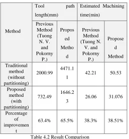
Method
Tool path
length(mm)
Estimated Machining
time(min)
Previous Method
(Tuong N. V.
and Pokorny
P.)
Propos
ed
Metho
d
Previous Method (Tuong N.
V. and Pokorny
P.)
Propose
d
Method
Traditional method (without partitioning)
2000.99 4471.1
1 42.21 50.53
Proposed method
(with partitioning)
732.49 1646.2
3 26.06 31.076
Percentage of improvemen
t
63.4% 65.5% 38.3% 38.51%
Table 4.2 Result Comparison
5. Conclusion and future works
From the previous literature it apparent that the various efforts have been made by entire research community to improve the surface machining quality and optimization of tool path length. But it still needs to improve the surface quality which depends upon computational approaches. From the theoretical, simulation and virtual test experimental results it can be concluded that the partitioning of the surface plays an important role to optimize the tool path length and improves the quality of surface machining with optimum time. In the current research work, the techniques developed for optimization of tool path length and improvement of surface quality with minimum time is still an open area of the research are number of interesting directions to pursue as future work. In this research, Bezier surface is used for machining process. However more flexible free form surfaces like B-spline and NURBS can be used for machining process to optimize the tool path length and improvement of quality of surface machining.
References
1. Makhanov, S. S. and Anotaipaiboon, W., “Advance numerical methods to optimize cutting operations in five axis milling machining”, Springer Publication, 2007.
2. Warkentin A, Ismail F and Bedi S., “Multi-point tool positioning strategy for 5 axis machining of
sculptured surfaces”. Computer Aided Geometry Design, Vol 17, 2000, pp. 83-100.
3. Tuong N. V. and Pokorny P., “A practical approach for partitioning free-form surfaces”, International Journal of Computer Integrated Manufacturing, Vol 23, No. 11, 2010, pp. 992– 100.
4. Radzevich, S.P., “A cutting-tool-dependent approach for partitioning of sculptured surface”. Computer-Aided Design, Vol 37, No. 7, 2005, pp. 767–778.
5. Ding, S., Mannan, M.A., Poo, A.N., Yang, D.C.H., and Han, Z., “Adaptive iso-planar tool path generation for machining of free-form surfaces”, Computer-Aided Design, Vol 35, No. 3, 2003, pp. 141–153.
6. Elber, G. and Cohen, E., “Second order surface analysis using hybrid symbolic and numeric operators”. Transactions on Graphics, Vol 12,No. 2, 1993, pp. 160–178.
7. Han Z.L., Yang D.C.H., “Iso-phote based tool-path generation for machining free- form surfaces”, Journal of Manufacturing Science and Engineering, ASME Transactions; Vol 121, No. 4, 1999, pp. 656-64.
8. Han Z.L., Yang D.C.H. and Chuang JJ.
“Isophote-based ruled surface approximation of free-form surfaces and its application in NC machining”, International Journal of Production Research, Vol 39, No. 9, 2001, pp. 191-130. 9. Yang D.C.H., Han Z., “Interference detection and
optimal tool selection in 3-axis NC machining of free-form surfaces”, Computer-Aided Design, Vol 31, No. 5, 1999, pp. 303-315.
10. Yin Z., “Adaptive tool path generation from measured data”, Proceedings of the Institution of Mechanical Engineers - Part B: Engineering Manufacture, Vol 218, No. 1, 2004, pp. 103-11. 11. Yin Z.W. and Jiang S.W., “Iso-phote based
adaptive surface fitting to digitized points and its applications in region-based tool path generation, slicing and surface triangulation”, Computers in Industry, Vol 55,No. 1, 2004, pp. 15-28.
12. ElberG., “Freeform surface region optimization for 3- axis and 5-axis milling”, Computer-Aided Design, Vol 27, No. 6, 1995, pp. 465–470.
13. Tang, K. and Liu Y. J., “An optimization algorithm for free-form surface partitioning based on weighted Gaussian image”. Graphical Models Vol 67, 2005, pp. 17–42.
www.ijiset.com 15. Wang, J., “Global finish curvature matched
machining”, Thesis (MS). Brigham Young University, 2005.
16. Rao, A. and Sharma, R., “On local gouging in five-axis sculptured surface machining using flat-end tools”. Computer-Aided Design, Vol 32, No. 7, 2000, pp. 409–420.
17. Gani, E. A., Kruth, J. P., Vanherck, P., and Lauwers, B., “A geometrical model of the cut in five-axis milling accounting for the influence of tool orientation”, International Journal of Advanced Manufacturing Technology, Vol 13, No. 10, 1997, pp. 677–684.
18. Jun, C.-S., Cha, K., and Lee, Y.S., “Optimizing tool orientations for 5-axis machining by configuration-space search method”, Computer- Aided Design, Vol 35, No. 6, 2003, pp. 549–566. 19. Y-S Lee, T.-C. C., “Automatic cutter selection for
five-axis sculptured surface machining”. International Journal of Production Research, Vol 34, No. 4, 1996, pp. 977–998.
20. Lee, Y. S., “Admissible tool orientation control of gouging avoidance for 5-axis complex surface machining”, Computer-Aided Design, Vol 29,No. 7, 1997, pp. 507–521.
21. Lee, Y.S. and Ji, H., “Surface interrogation and machining strip evaluation for 5-axis CNC die and mold machining”. International Journal of Production Research, Vol 35, No. 1, 1997, pp. 225–252.
22. Lo, C. C.,” Efficient cutter-path planning for five-axis surface machining with a flat-end cutter”. Computer-Aided Design, 31, No. 9, pp. 557– 566, (1999).
23. Anotaipaiboon, W. and Makhanov, S. S., “Tool path generation for five-axis NC machining using adaptive space-filling curves”. International Journal of Production Research, Vol 43, No. 8, 2005, pp. 1643–1665.
24. Besl P. J., “The free-form surface matching problem, in Machine Vision for Three-Dimensional Scences”, Academic Press, San Diego (H. Freeman, Ed.), 1990, pp. 25–71.
25. Dorai, C. and Jain A. K., “COSMOS-A representation scheme for 3D free-form objects”, IEEE Trans. Pattern Anal. Mach. Intell, Vol 19, 1997, pp. 1115–1130.
26. Stein F. and Medioni, G., “Structural indexing: Efficient 3-D object recognition’. IEEE Trans. Pattern Anal. Mach. Intell. Vol 14, 1992, pp. 125–145.
27. Brown C. M., “Some mathematical and
representational aspects of solid modeling”. IEEE Trans. Pattern Anal. Mach. Intell, Vol 3, 1981, pp. 444–453.
28. Flynn P. and Jain A. K., “Bonsai 3D object recognition using constrained search”. IEEE Trans. Pattern Anal. Mach. Intell, Vol 13, 1992, pp. 1066–1075.
29. Radzevich, S.P., “R-surfaces: A novel tool for partitioning of a sculptured surface”. Mathematical and Computer Modelling, Vol 46, No. 9-10, 2007, pp. 1314–1331.
30. Li, L.L. and Zhang, Y.F., “Cutter selection for 5-axis milling based on surface decomposition”, 8th International Conference on Control, Automation, Robotics and Vision, Kunming, China, Vol 3, 2004, pp. 1863–1868.
31. Chen, Z.C., Dong, Z., and Vickers, G.W., “ Automated surface subdivision and tool path generation for 3½½- axis CNC machining of sculptured parts”. Computers in Industry, Vol 50, No. 3, 2003, pp. 319–331.
32. Radzevich, S.P., “CAD/CAM of Sculptured surfaces on multi-axis NC machine; The DG/K-based approach”. San Rafael, CA: Morgan & Claypool, 2008.
33. Ding, S., Mannan, M.A., Poo, A.N., Yang, D.C.H., and Han, Z., “The implementation of adaptive isoplanar tool path generation for the machining of free-form surfaces”, International Journal of Advanced Manufacturing Technology, Vol 6, No. 7-8, 2005, pp. 852–860.
34. Park, S.C. And Choi, B.K., “Boundary extraction algorithm for cutting area detection”, Computer-Aided Design, Vol 33,No. 8, 2001, pp. 571–579.
35. Makhanov, S.S. and Anotaipaiboon, W.,”
Advanced numerical methods to optimize cutting operations of five axis milling machines”. Berlin: Springer-Verlag, (2007).
36. Li, L.L. and Zhang, Y.F.,” Flat-end cutter accessibility determination in 5-axis milling of sculptured surfaces”. Computer-Aided Design and Applications, Vol 2, No. 1-4, 2005, pp. 203–212. 37. Li, L.L. and Zhang, Y.F.,” An integrated
approach towards process planning for 5-axis milling of sculptured surfaces based on cutter accessibility map”. Computer-Aided Design and Applications, 3,No. 1-4, pp. 249–258, (2006). 38. Rao N, Ismail F, Bedi S.,” Tool path planning for
www.ijiset.com 39. Roman, A., Bedi, S., and Ismail, F., “Three-half
and half-axis patch-by-patch NC
machining of
sculptured surfaces”, The International
Journal of Advanced
Manufacturing Technology, Vol 29, No. 5-6, 2006, pp. 524–531.
40. Lu, G., “Chain code-based shape representation and similarity
measurer”, In:
C.H.C. Leung, ed. Visual information systems. Berlin:
Springer-Verlag, Vol 1306, 1997, pp. 135–150.
41. “CAD/CAM-Theory and Practices”, Ibrahim Zied and S Subramanium, TMH Publication.
42. Tiwari, P., “Tool path generation for Bezier surface for constant scallop height”, M.Tech. Thesis, ITGGV Bilaspur (2013).
AUTHORS
Jeenendra Kumar Shiv, he did his BE in Mechanical Engineering from Rungta College of Engineering and Technology in 2009 and M.Tech from Institute of Technology Guru Ghasidas University Bilaspur in 2014. He is working as Assistant Professor in Mechanical Engineering Department in Parthivi College of Engineering and management BHILAI.
Sushant Kumar Gain, he did his BE in Mechanical Engineering from Chhatrapati Shivaji Institute of Technology in 2009 and is pursuing his M.Tech in From Sri Shankaracharya Group of Institution.
Laxmi Kant Sahu received the Bachelors of Technology degree in Mechanical Engineering from Government Engineering College, Bilaspur, Chhattisgarh Swami Vivekananda Technical University, Bhilai, Chhattisgarh, India in 2010 and Masters of Technology in Machine Design from Guru Ghasidas Vishwavidyalaya (A central university),