P a g e | 1834
Prediction of Fatigue Cracking In Life Edge Has Achieved a Single Package
Using the Exponential Model
1. R.PRUDHVI RAJU,2. Dr.B.S.R.MURTHY
1
PG SCHOLAR, DEPEARTMENT OF MECHANICAL ENGINEERING,SRISAI EDUCATIONAL SOCIETY'S
GROUP OF INSTITUTIONS-KODAD
2
PROFESSOR, DEPEARTMENT OF MECHANICAL ENGINEERING,SRISAI EDUCATIONAL SOCIETY'S
GROUP OF INSTITUTIONS-KODAD
ABSTRACT: Metal beams are extensively used in structures, automobile sectors and machine
components. Some of their applications include connecting rod of IC engine, shafts, axles, and
gears, structures members of bridges and also components of machines. Most of them experience
fluctuating or cyclic load condition in their service life’s such loading conditions may initiate a
crack and cause fatigue crack growth. The monitoring and modelling of fatigue crack growth are
necessary for the stability and safety of machines and structures. In the present investigation an
attempt has been made to develop a fatigue life prediction methodology by using an Exponential
Model in single edge notched (SEN) cracked beams. The predicted results are compared with
experimental crack growth data. It has been observed that the results obtained from the models
are in good agreement with experimental data.
Keywords: -Beams, crack profile, fatigue crack propagation, constant amplitude loading, life
prediction, exponential model.
INTRODUCTION
Failure due to repeated loading, that is
fatigue, has accounts for at least half of this
mechanical failure. No exact data is
available, but many books and articles have
suggested that between 50 to 90 per cent of
all mechanical failures are due to fatigue,
most of this is unexpected failures. In many
situations a beam experiences fluctuating
loading conditions. This may initiate and
propagate a crack. The monitoring and
modelling of fatigue crack growth is more
significant for the stability and safety of
machines components, bridges, aircraft and
structures. In this project (EN8) medium
carbon steel beam is used. In fatigue fracture
the stress is generally below the yield stress.
In general ductile material deforms before
fracture and gives warning before failure of
a component but in case of fatigue failure
the ductile materials fails suddenly. This
becomes more significant when failure is
related to automobile sectors or machinery
work being done. In a dynamic world,
however, failure occurs at stresses much
below the materials ultimate strength or
yield strength. This phenomenon, failing at
relatively low stresses, came as quite a
surprise to most engineers in the early years
of metal component design and
manufacturing. The other frustrating aspect
is that the material exhibited no sign of its
tiredness or fatigue and could fail without
much warning. This could be more
dangerous if proper selection of design
criteria is not selected and validation of
those criteria with experiment is not done.
There are many areas where the fatigue
criteria should be in mind before designing
the component.
OBJECTIVES The objective of present
work is: To develop compliance correlation
of a-N data and estimation of fatigue crack
propagation life by using exponential model.
1. To conduct fatigue crack propagation
test of supplied (EN8) medium
carbon steel under constant
amplitude loading condition with
different stress ratios.
2. To propose an exponential model to
predict fatigue crack propagation in
single edge notched cracked beam.
The crack initiation starts in a point where
the stress concentration is high. This stress
concentration may be due to abrupt change
in cross section or due to defect present
within the system. The change of the cross
section can do in such a way that the stress
concentration will be lower. But the defect
due to manufacturing process cannot be
eliminated completely because of the
complex nature of manufacturing and
human interference.
EXPERIMENTAL INVESTIGATION
The fatigue crack propagation tests were
conducted on (EN-8) medium carbon steel
beams. All the tests were conducted in a
servo-hydraulic dynamic testing machine
(Instron-8800) using through crosssectional
of cracked beam specimen under load
control mode. A four point bend fixture was
fabricated for conducting fatigue crack
propagation tests. Before conducting the
test, COD gauge was calibrated for single
edge straight notched cracked beams
specimens. All the tests were conducted in
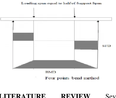
air and at room temperature. Four Points
bend Method: Four point bending (FPB) is a
cornerstone element of the beam flexure
portion of a sophomore level mechanics of
materials course. The FPB lecture has
traditionally developed the theory from body
diagram through beam deflection, with
P a g e | 1836
analytical practice. In FPB method Beam
flexure represents one of the three most
common loading categories for mechanical
systems. As such, it is on the syllabi of
nearly all sophomore- level mechanics of
materials courses, including the mechanical
engineering technology course under
consideration here. Within the lecture
setting, FPB theory is developed from
free-body diagram through beam deflection. This
theory is reinforced by analytical practice
solving related homework problems. By this
FPB the result to experimentally and
analytically verify and Validated beam
flexure theory. According to the convention
specified in ASTM D6272-00 transverse
vertical loads are applied to horizontal
beams such that a constant bending moment
results between the two inner load locations.
Figure below shows the corresponding
loading diagrams, from free-body to bending
moment. The major difference between the
three point and four point flexural tests is the
location of bending moment. The four point
bending method allows for uniform
distribution between the two loading noses,
while the three point bending method, stress
is located under the loading nose. But in
four point bending test, no shear force acts
in between two inner spans, while in case of
three point bending test maximum shear
force act a loading nose.
LITERATURE REVIEW Several
experiments and models have been proposed
till date in order to predict fatigue crack
propagation with load control method under
constant amplitude loading conditions with
different stress ratios with the help of
INSTRON-8800. Generally crack length is
measured by travelling microscope
determined by mathematical modeling of
standard specimens or by empirical
relationship or by experimental
investigation. We are here doing the
experimental procedur e to find out the
crack length for beams. Generally
compliance crack length relationship and
four point bend test are used for
determination of crack growth. The
objective of present work is to develop
compliance correlation of a-N data and
estimation of fatigue crack propagation life
by using exponential model. Cyclic fatigue
involves the microstructural damage and
failure of materials under cyclically varying
rarely designed with compositions and
microstructures optimized for fatigue
resistance. Metallic alloys are generally
designed for strength, intermetallics for
ductility, and ceramics for toughness; yet, if
any of these materials see engineering
service, their structural integrity is often
limited by their mechanical performance
under cyclic loads. In fact, it is generally
considered that over 80 percent of all service
failures can be traced to mechanical fatigue,
whether in association with cyclic plasticity,
sliding or physical contact (fretting and
rolling contact fatigue), environmental
damage (corrosion fatigue), or elevated
temperatures (creep fatigue). Accordingly, a
large volume of literature has been amassed
particularly over the past twenty-five years,
dealing with the mechanics and mechanisms
of mechanical fatigue failure [1, 2].
Subcritical crack growth can occur at stress
intensity K levels generally far less than the
fracture toughness Kc in any metallic alloy
when cyclic loading is applied (∆KTH/Kc is
nearly equal to 0.1 – 0.4). In simplified
concept, it is the accumulation of damage
from the cyclic plastic deformation in the
plastic zone at the crack tip that accounts for
the intrinsic mechanism of fatigue crack
growth at K levels below Kc. The process of
fatigue failure itself consists of several
distinct processes involving initial cyclic
damage (cyclic hardening or softening),
formation of an initial „fatal‟ flaw (crack
initiation), macroscopic propagation of this
flaw (crack growth), and final catastrophic
failure or instability. The physical
phenomenon of fatigue was first seriously
considered in the mid nineteenth century
when widespread failures of railway axles in
Europe prompted Wohler in Germany to
conduct the first systematic investigations
into material failure under cyclic stresses
Wohler, 1860 [3]. However, the main
impetus for research directed at the crack
propagation stage of fatigue failure, as
opposed to mere lifetime calculations, did
not occur until the mid-1960s, when the
concepts of linear elastic fracture mechanics
and so-called „defecttolerant design‟ were
first applied to the problem of subcritical
flaw growth (Paris et al., 1961; Johnson and
Paris, 1967). Such approaches recognize that
all structures are flawed, and that cracks
may initiate early in service life and
propagate subcriticaly. This paper [4, 5]
presents the fatigue crack growth analysis on
the perforated wide flange I-beam which is
subjected to constant amplitude bending
loadings. I-beam of grade steel is widely
used in building and other structural
constructions. The detailed geometries
according to the size and weight have been
P a g e | 1838
I-beam has a significant contribution in
building and other structural constructions,
careful considerations has to be taken if
defects or cracks are present in the beams.
Many researchers have reported the
behaviors of beam. Dunn et al.have
introduced closed-form expressions for
stress intensity factors for cracked square
-beams subjected to a bending moment. GAO
and Herman [6] have estimated the stress
intensity factors for cracked beams. Most
structural components are often subjected to
cyclic loading, and fatigue fracture is the
most common form of failure. In general,
fatigue process consists of three stages:
initiation and early Crack propagation,
subsequent crack growth, and final fracture.
The fatigue crack growth rate, da/dN, which
determines the fatigue life of the cracked
components, has extensively been
investigated experimentally and
theoretically. Stephens et al. [7] reported
that fatigue crack growth curve for constant
amplitude loading consisting of the crack
growth rate (da/dN) versus the stress
intensity factor range (ΔK) in the log–log
scale typically includes three regions.
Region-I is the near threshold region and
indicate the threshold (ΔKth) value which
there is no observable crack growth.
Microstructure, mean stress, frequency, and
environment mainly control Region I crack
growth. Region II corresponds to stable
macroscopic crack growth that is typically
controlled by the environment. In Region III
the fatigue crack growth rates are very high
as they approach to instability. In Region III
crack growth is often ignored in practice due
to the insignificant fatigue life remaining
upon entering the region. Structural
engineers have been utilizing numerical
tools/ software packages of Finite Element
Method or Boundary Element Method to
assess their designs for strength including
crack problems. BEM has emerged as a
powerful alternative to Finite Element
Method (FEM) for cases where better
accuracy is required due to situations such
as stress concentration (as in the case of a
crack), or an infinite domain problem. Since
BEM only requires discretization of surfaces
(in case of 3D problems) and discretization
of lines (in case of 2D problems), it allows
modeling of the problem becoming simpler.
Aliabadi [8] reported various applications of
BEM to solve solid mechanics problems.
Boundary element formulations for
modeling the nonlinear behavior of concrete
were reported by Aliabadi and Saleh [9].
Fatigue crack growth is required for the
assessment of residual fatigue life, or for a
damage tolerance analysis to aid structural
design. In this paper fatigue crack growth of
constant amplitude bending loading are
presented. A quarter-elliptical corner crack
in a prismatic solid is analyzed as
benchmarking model for the available
analytical solution [10] prior to making
further modeling of the cracks. This paper
[11] examines the fatigue crack growth
histories of a range of test specimens and
service loaded components in Aircraft
structures and Joint failures. The crack
growth shows, as a first approximation a
linear relationship between the log of the
crack length or depth and number of cycles.
These cracks have grown from; semi- and
quarter elliptical surface cuts, holes, pits and
inherent material discontinuities in test
specimens, fuselage lap joints, welded butt
joints, and complex tubular jointed
specimens‟ .This application of exponential
crack growth are discussed. The stress
intensity factor range, ∆K has for many
years been known to have a significant
correlation with the crack growth rate,
da/dN. The first paper making this
correlation was published in 1961 by Paris,
Gomez and Anderson [12], who adopted the
K-value from the analysis of the stress field
around the tip of a crack as proposed by
Irwin in 1957 [13]. The results of the
constant-amplitude crack growth tests by
Paris were expressed in terms of da/dN
(where N is the number of fatigue cycles) as
a function of ∆K (which is Kmax - Kmin)
on a double log scale. Plotting such data
shows a region of growth where a linear
relation between log (da/dN) and log (∆K)
appears to exist. This paper examines the
Compliance crack length relations for the
four-point bend specimen geometry in the
laboratory. Crack lengths can be measured
by direct and indirect means. While direct
methods of crack length measurement, e.g.
by travelling microscope, are tedious and
prone to human error, the indirect methods
are not only
CONCLUSIONS
1. The calibration curve of COD gauge is
found to be straight line, which shows linear
relationship between COD gauge and crack
depth of straight notched beam.
2. The crack front profile is approximately
thumbnail shape in nature as the crack depth
increases.
3. Exponential model of the form has been
used for other specimen geometries and can
also be used to determine the fatigue life in
beams without going through numerical
integration.
4. Subsequently, to predict fatigue life, the
exponent, mij (specific growth rate) has
been judiciously correlated with crack
P a g e | 1840
material properties KC (for specific
specimen geometry) E, Ϭys and R in the
form of dimensionless quantities.
5. The proposed exponential model may be
used to predict fatigue crack propagation
under constant amplitude loading condition
with different stress ratios.
FUTURE WORK
1. The proposed models may be tested for
other specimen geometries.
2. The soft computing methods may be used
to determine the specific growth rate.
REFERENCES
[1] Suresh, S. (1991). Fatigue of Materials,
Cambridge University Press, Cambridge.
[2] Johnson, H.H. and Paris, P.C. (1967).
Subcritical flaw growth. Engineering
Fracture Mechanics 1, 3.
[3] Wohler, A. (1860). Versuche über die
festiykeit eisenbahnwagenuchsen.
Zeitschrift für Bauwesen 10.
[4] Crack Growth Analysis of Wide Flange
I-beam under Constant Amplitude Bending
Loadings. Euro Journals Publishing, Inc.
2009 by J. Purbolaksono, A.A. Ali, A.
Khinani, and A.Z. Rashid.
[5] M.L. Dunn, W. Suwito and B. Hunter,
Stress Intensity Factors for Cracked IBeams,
Engineering Fracture Mechanics, 1997, 57,
609-615.
[6] H. GAO and G. Herrmann, On Estimates
of Stress Intensity Factors for Cracked
Beams. Engineering Fracture Mechanics,
1992, 41, 695-706.
[7] R.I. Stephens, A. Fatemi, R.R. Stephens
and H.O. Fuchs, Metal Fatigue in
Engineering, New York: Wiley Interscience,
2001
[8] M.H. Aliabadi, the Boundary Element
Method, Chichester: John Wiley, 2002.
[9] M.H. Aliabadi and A.L. Saleh, Fracture
Mechanics Analysis of Cracking in Plain
and Reinforced Concrete Using the
Boundary Element Method, Engineering