R E S E A R C H
Open Access
Improved synchronization, channel estimation,
and simplified LDPC decoding for the physical
layer of the DVB-T2 receiver
Doaa H Sayed
1*, Maha Elsabrouty
2and Ahmed F Shalash
3Abstract
The newly developed 2nd generation standard for digital video broadcasting (DVB-T2) emerges as a significant upgrade over its first generation predecessor DVB-T. The DVB-T2 standard targets an increased system throughput by at least 30% over the DVB-T. This article introduces algorithms in the signal processing chain to improve the mobile operation for DVB-T2. The proposed modified synchronization blocks, along with the improved channel estimation, show significant improvement compared to the results reported in the DVB-T2 implementation guide. In addition, state-of-the-art low-complexity algorithms in the bit processing chain, particularly in the LDPC decoder, are used to provide robustness and support throughput increase, while reducing the implementation complexity. The integrated system is simulated including implementation effects. The simulation results confirm the enhanced performance of the developed integrated model and provide better results compared to those reported in literature.
1. Introduction
The first generation terrestrial digital video broadcasting standard, DVB-T, introduced a breakthrough in TV trans-mission with well-structured transtrans-mission chain that is based on OFDM and powerful forward error correction. Recently, the state-of-the-art technology in the digital communication and the economics of digital transmission has developed considerably, enabling a second generation of the DVB standards to emerge, DVB-T2.
The DVB-T2 standard was introduced in 2010 [1], providing an advancement of the terrestrial video trans-mission. DVB-T2 can achieve a capacity increase by at least 30%. compared to its predecessor DVB-T [2]. In fact, DVB-T2 is taking serious steps to effectively replace the DVB-T in Europe. Several innovative business models to benefit from its improved capacity and performance have been developed [3]. However, the ambitious increase in the throughput can be useful under mobile channel conditions only if the DVB-T2 receiver is carefully designed. More specifically, the channel estimation and
synchronization blocks play the main role in enhancing the performance in mobile reception scenarios.
This article focuses on improving the performance of channel estimation and synchronization blocks along with a low-complexity LDPC decoder. A modification to the synchronization block is added to improve its per-formance and eliminate the need for an extra timing synchronization stage. Efficient implementation, with im-proved performance channel estimation, is employed to better suit the mobile channel compared to the rather li-mited channel estimation proposed in the DVB-T2 imple-mentation guide [4]. On the other hand, a low-complexity layered decoder is employed to reduce the implementa-tion cost of the LDPC decoder. By combining these modifications together, an enhanced performance lower complexity DVB-T2 receiver is obtained. Numerical re-sults show improved performance of the integrated design when compared to results reported in an example existing industrial solution [5] as well as improved performance of the individual targeted blocks when compared to the im-plementation guide [4].
The remainder of the article is organized as follows: Section 2 is dedicated to the improvement in the re-ceiver signal processing chain, namely, the introduced * Correspondence:[email protected]
1
Varkonsemiconductors, El Gezirah Tower 1, next to El-Sadat Academy, 9th floor, Maadi, Cairo, Egypt
Full list of author information is available at the end of the article
algorithms for synchronization and channel estimation. Section 3 highlights the LDPC decoder employed in the receiver along with possible efficient storage procedure of the parity check matrix which helps in reducing the complexity and memory requirement. Section 4 intro-duces the integrated DVB-T2 model simulation results in different channel conditions. Section 5 presents a conclusion and summary of the study.
2. Improved DVB-T2 synchronization and channel estimation design
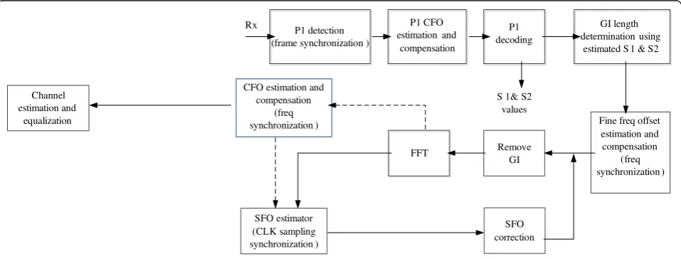
The general structure of the DVB-T2 receiver signal pro-cessing chain is shown in Figure 1. The signal propro-cessing chain in the receiver is mainly responsible for compensa-ting the channel effects and performing synchronization and proper detection of the frames. This section presents our contribution towards modifying critical blocks in the signal processing chain, namely the synchronization block [including frame synchronization, i.e., coarse time synchronization and coarse frequency offset (CFO) com-pensation], and the channel estimation block. The algo-rithms used in the design of these blocks are either newly developed or improved implementations of selected state-of-the-art algorithms in wireless communications. They meet the requirement of robust and improved perfor-mance while maintaining low-complexity constraints.
2.1. Synchronization
Accurate synchronization should be implemented to achieve robust reception of the DVB-T2 signal. In general, the synchronization process in DVB-T2 is achieved in two categories:
(i) Timing synchronization: Coarse time
synchronization (Frame synchronization), and fine timing synchronization.
(ii)Frequency synchronization: Both fine and CFO estimation and compensation.
2.1.1. Coarse time synchronization
In this section, we propose a modification to the coarse time synchronization block to improve its performance. This is done in two steps: (1) Changing the correla-tion circuit involved in the deteccorrela-tion of preamble P1. (2) Threshold comparison circuit with emphasis on choosing an appropriate threshold level.
The T2-frame always begins with a P1-preamble that has a special structure as shown in Figure 2. The first stage in synchronization, referred to as“Frame synchro-nization”, intends to capture the start of the T2 frame. DVB-T2 makes major use of the special structure of the preamble P1 in achieving synchronization. The main middle part of the P1 symbol, called part A, comprises
an OFDM symbol which has a length NA of 1024
subcarriers. This part of the P1symbol is surrounded by two frequency shifted versions of the part A. The part C in the P1 symbol is of length Nc = 542 and it is a
fre-quency shifted version of the first 542 samples of middle part A. The part B of length NB = 482 is a frequency
shifted version of the last 482 samples of part A. The DVB-T2 implementation guide presents an algorithm for coarse timing synchronization using P1. This algo-rithm is based on a double branch correlator.
In our proposed circuit, the original algorithm pro-vided in the implementation guide is further modified into two ways. In order to achieve an accurate estima-tion of the FFT window posiestima-tion (in case of no fading), the running average filter span is modified to the length
Tc=Nc×Tin the upper branch and the lengthTB=NB× T, in the lower branch instead ofTA, whereTA=NA×T, and T is the chip rate. The modified correlation circuit is shown in Figure 3. In the figure, the delay applied in
Fine freq offset
estimated S 1 & S2
Channel
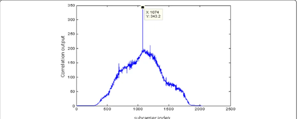
the upper correlation branch is also modified to 2TB instead of the original length TA. These modifications not only improve the resulting peak of the correlation, but also reduce the computations required in the synchro-nization operation. Figure 4 presents the output of the correlation of the proposed P1 detection circuit. The figure indicates that the proposed design eliminates the flat trapezoidal shape which results in the original algo-rithm correlation output, and produces a clear peak indi-cating a clear maximum of the correlation with quadratic decaying neighboring points. Thus, the need for an extra fine timing symbol synchronization step is eliminated.
The threshold comparison block is our second modifi-cation to enhance the peak detection. The resulting
correlated signal output is compared to a threshold related to the power in the P1 signal. In the previous algorithm, a suitable threshold could be calculated as follows:
Threshold¼FACTOREBEc ð1Þ
where EB is the energy in the samples with length Tb
preceding the peak position in branch B, EC is the
energy in the samples with lengthTc preceding the peak
position in branch C, and FACTOR is decided through
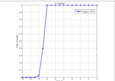
the simulations. Figure 5 shows the probability of correct detection for FACTOR = 1/256 which is better than the resultant one shown in the DVB-T2 implementation s
Tc=59µ TA=112µs Tb=53µs
Figure 2P1 frame structure [4].
Tb Tb
Figure 4Correlation output of the proposed coarse timing synchronization block.
guide [4] in case of AWGN channel. The peak is not de-clared directly after exceeding the threshold. However, when this threshold is exceeded by the correlation out-put, the correlation values after the threshold are kept for a predetermined period to choose the maximum value. This limits the possibility of false detection of P1, when the frame is not captured at its beginning. It is worth noting that in [6], similar work was delivered in-dependently based on modifying the implementation guideline circuit. This modification is used to produce a modified P1 detection circuit with linear decaying rate around the maximum peak.
The algorithm is tested under Rayleigh Channel fading (Mobile Channel, TU-6) which has been defined by COST 207 [7] as a typical urban profile. TU-6 is mainly composed of six paths having wide dispersion in delay and relatively strong power. Figure 6 shows the histo-gram of the peak detection position. Using our modi-fied algorithm enhances the performance of this coarse timing estimation step. The modified synchronization algorithm needs only a maximum margin of 16 points into the guard interval to insure the position in the cy-clic prefix.
2.1.2. CFO
The fractional part of the frequency offset is estimated and compensated using the algorithm in the DVB-T2 implementation guide [4]. The integral part of frequency offset is referred to as CFO. CFO can be estimated in two stages using P1 and P2 symbols in the frequency domain. The DVB-T2 implementation guide does not disclose a specific detailed procedure to estimate and compensate the CFO. In the following we present our proposed modified CFO estimation and compensation, which is based on a modification of the algorithm in [8]
to improve its performance when applied to the DVB-T2 signal.
CFO is done in two stages. In the first stage, FFT of resolution 1024 is applied to the detected time domain P1 symbol (the main part of the P1 symbol, i.e., part A) then a correlation is done between the active carriers and the detected P1. This operation is repeated for shifted versions of active carriers. The initial estimate of the coarse offset is compensated for in the rest of the frame by multiplying with the inverse phase. Simulation of the modified CFO is done under the assumption of SNR = 0 dB, Rayleigh fading and offset equals to 50 sub-carrier spacing of 1024 OFDM signal. The result is shown in Figure 7. In the second stage, the residual CFO is estimated using the continual pilots P2 symbol similar to the algorithm in [8].
The algorithm for the second stage of the CFO recov-ery is modified by comparing only a specific subset of the P2 pilots recorded in lookup tables. The modifica-tion is required because of the intricacies of DVB-T2 sig-nal in case the CFO is equal to, or more than, three times subcarrier spacing in the presence of Rayleigh channel and with strong noise. This will generate more than one peak leading to an erroneous decision. This is due to the nature of the pilots, which repeat every three subcarriers. For example, if the CFO = 3 times sub-carrier spacing, then we shift the received signal for cor-relation process from–15:15 and at shift = 3. There are several pilots which can, in the presence of channel and noise, produce a second peak with a wrong decision as illustrated in Figure 8. This problem is eliminated using the new proposed algorithm as shown in Figure 9. Thus, the pilots that cause the problem are eliminated and the appropriate subset of pilots is stored in lookup tables. Figure 10 illustrates the probability of correcting the
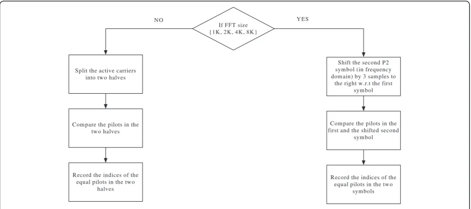
residual CFO estimation from P2 before and after modi-fication. The algorithm, based on comparing the pilots to a lookup table, was implemented according to the flowchart in Figure 11. The construction of the lookup table is done based on two sets of pilots extracted either from two consecutive P2 symbols for FFT sizes ranging between 1-k up to 8-k or only one symbol in case of
FFT sizes 16K or 32K (in this case, they are split into two halves). A record of similar pilots’indices in the two sets is formed by comparing the two pilot sets in the first symbol and the shifted second symbol for all the FFT sizes and using it as lookup table.
Using the lookup tables, the CFO is estimated as illus-trated in Figure 12. The algorithm is applied and Figure 7output of correlation versus subcarrier index in case of estimating CFO from P1 preamble.
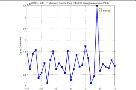
Figure 9Output of correlation in case of estimating residual P2 CFO from lookup table pilots with CFO = 9 and P1 rayleigh fading channel.
repeated with different positive and negative offsets, and then the peak is picked corresponding to the CFO.
2.2. Channel estimation
The channel estimation suggested by the DVB-T2 imple-mentation guide is a linear interpolation channel estima-tor in both time and frequency directions, which has the advantage of low complexity but its performance is very poor in fading channels. Instead we employ a robust esti-mator that does not require the channel profile knowledge. Although its implementation complexity is comparable to
the linear channel estimator, the performance of the robust estimator is, by far, superior to the linear estimator cur-rently reported in the DVB-T2 implementation guide.
In general, DVB-T2 operation in fading channels is di-rectly affected by the channel estimation technique used. The choice of the channel estimation becomes more crucial with the DVB-T2 migrating to mobile applica-tion. A careful inspection of the channel estimation uti-lized in the DVB-T2 implementation guide reveals its reliance on 1D cascaded linear interpolation in time and frequency domains. However, the performance of this
If FFT size
Com pare the pilots in the first and the shifted second
sym bol
Record the indices of the equal pilots in the tw o
sym bols Split the active carriers
into tw o halves
Com pare the pilots in the tw o halves
Record the indices of the equal pilots in the tw o
halves
Y ES N O
Figure 11Flow chart for picking the two sets of pilots in two consecutive P2 symbols.
Extract the pilots in the P2 symbol(s) according to the
lookup table
Multiply the first set of pilots with the conjugate of the second set and sum
the result
Add the offset value to the indices of the lookup table Repeat
first-order interpolation is generally mediocre [9]. The literature of channel estimation classifies the estimator types into two main categories: Decision directed and pilot-aided channel estimation (PACE). The DVB-T2 provides eight different pilot patterns, named PP1,. . ., PP8, which implies clearly limiting our search to the pool of the PACE algorithms which generally perform better than the decision directed algorithms. In the lit-erature of PACE algorithms, minimum mean square error (MMSE), also referred to as Wiener-based estima-tor, stands out as the measuring stone to all other algo-rithms. MMSE provides the optimal linear estimation in the mean square error (MSE) sense [10,11]. However, a major problem with MMSE estimation is that it re-quires the knowledge of the exact channel correlation functions. The channel correlation functions are usually unknown and time varying, which makes this technique impractical. This is one of the main reasons the DVB-T2 implementation guide favored linear interpolation. In fact, the linear interpolation method is chosen mainly due to two main factors: the first is its simplicity; the second reason is its independence of the changing chan-nel profile in mobile environment.
In [10], a robust MMSE channel estimation is deve-loped. The robust algorithm is based on using a generic robust correlation function that gives acceptable MSE for all channel correlations. The used solution employs a uniform power delay profile which is longer than the channel delay spread as well as a uniform Doppler spec-trum profile with Doppler frequency higher than that of the channel. The main advantage of this algorithm is that the filter coefficients do not depend on the channel profile. They can be calculated a priori and stored in a memory at the receiver side to be applied on the least
squared (LS) estimate of the channel at pilot positions. The robust estimator has many advantages: (1) It ex-hibits performance which is very similar to the optimal channel estimation. (2) It does not require the know-ledge of the channel profile and is thus immune to de-gradation in performance when operating in a fast changing mobile environment. (3) The complexity of the robust estimator is much less than the MMSE solution. The robust estimator depends on a single channel pro-file and the filter coefficients are pre-computed and stored. This relieves the load of an on-line updated cal-culation of the channel coefficients which includes the inversion of a high order matrix.
A one-dimensional (1D) cascaded linear interpolation/ Robust Wiener filtering is considered for the channel estimation. During the first step, anLS estimate of the channel response is made at the pilots, then linear interpolation is carried out in the time domain to obtain accurate estimations at the in-between subcarriers. Linear time interpolation or “time averaging” is used to get the pseudo pilots that are the circled subcarriers illustrated in Figure 13. In the second step, frequency domain estimation utilizes both the original pilots and
Frequency Axis
Added Pilot – using time interpolation (piecewise linear, or piecewise constant) or time filtering
Data Subcarrier – estimated using frequency linear interpolation or filtering
Figure 13Creating pseudo carriers in the time domain method (PP2 pilot pattern).
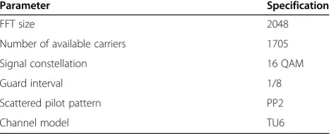
Table 1 The simulation configuration for channel estimation
Parameter Specification
FFT size 2048
Number of available carriers 1705
Signal constellation 16 QAM
Guard interval 1/8
Scattered pilot pattern PP2
the newly generated pseudo pilots. The pilots are passed to the 1D filter (1D robust MMSE) to get the remaining data subcarriers in each symbol:
e
H m½ ¼Xm1∈p
mC m½ 1
e
H m½ 1; ð2Þ
Where H me½ is the estimated complex channel
fre-quency response at location m on the time/frequency
grid, and H m^½ is the LS estimates for pilot locations and the time interpolated pseudo-pilots. C[m1] is the
complex Wiener filter coefficients that can be calculated as in [12], and m1 belongs to the indices of the nearest
LS pilots in the same OFDM symbol to the required subcarrier m. The set Pm represents the Nt pilot loca-tions nearmwhereNtis the number of the filter coeffi-cient. When utilizing the nearest pilots in the frequency domain estimation, the middle part of the coefficients is periodic. Using this property the calculation process of the robust filter coefficients can be further reduced by up to 90% in some cases. This could be valuable, with Figure 14Performance of PP2 pilot pattern channel estimation for 2k OFDM mode and 40 Hz Doppler frequency.
the need to store the coefficients for the different pilot patterns and different OFDM sizes.
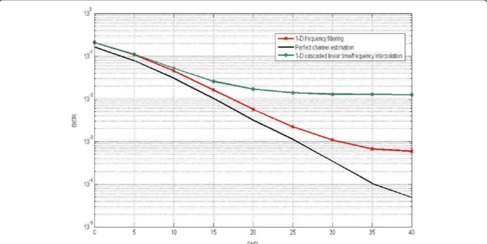
The method, referred to as “1D frequency filtering”, is compared to the method proposed in the DVB-T2 im-plementation guideline, referred to as“1D cascaded time/ frequency interpolation”. In our simulation, perfect time and frequency synchronization is assumed. The simula-tion is applied to TU6 channel model with Doppler shifts of 40 and 100 Hz. The chosen bandwidth is 8 MHz. Table 1 presents the simulation configuration parameters.
Figures 14 and 15 present the bit error rate (BER) per-formance of PP2 scattered pilot pattern for Doppler fre-quencies 40 and 100 Hz, respectively. The figures clearly show the improved performance of the robust estimator. This improvement comes at minimum possible added complexity as the robust algorithm utilizes hybrid linear time interpolation/robust frequency interpolation. Re-cently, the research group came across a linear mini-mum square errorproposed for DVB-T2 system in [13]. The channel estimation in [13] is simulated using the same channel parameters we used in Table 1, except for using QPSK mapping rather than the 16 QAM constel-lation which we employed. The QPSK is known to have a better error rate performance. However, even with the higher 16 QAM constellation we used, the 1D frequency filtering channel estimation employed here outperforms the reported results in [13] for the respective scattered pilot patterns. Similar results were obtained for different pilot patterns and different OFDM sizes.
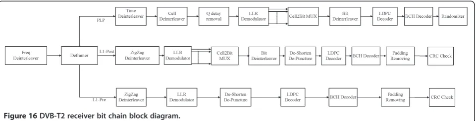
3. Bit processing chain
The improved structure of the signal processing chain of the DVB-T2 receiver is complemented with an enhanced bit processing chain structure to improve the overall performance of the receiver. The bit processing chain structure is illustrated in Figure 16. The implementation of the bit chain receiver involves a state-of-the-art log-likelihood soft demapper, and BCH decoding [14-16]. On the other hand, the LDPC decoder poses a particular implementation challenge regarding the algorithmic and implementation complexity, not to mention its memory requirements. To begin with, an efficient low
complexity-high performance decoder is required. To reduce the memory requirements, an efficient storage procedure for the parity check matrix at the receiver side is also needed.
3.1. Layered decoding for DVB-T2 LDPC codes
LDPC codes are first introduced as linear binary codes [17,18]. The Tanner graph [19] is used to represent con-nections and edge links. An edge links the check node i
to the variable node j if the element Hij of the parity check matrix is non-null. Decoding algorithms based on Tanner graphs are iterative, based on exchanging infor-mation between parity check nodes and variable nodes. Belief propagation is applied to Tanner graphs to effi-ciently decode LDPC codes [20,21].
Soft decoding algorithms dominate the scene in real application of LDPC decoding. In general, LDPC de-coding algorithms can be seen as an approximation of belief propagation decoding. Improvements to the belief propagation through scaling have been addressed in se-veral publications [21-24]. Min-Sum decoding is used in our proposed decoder. The main reason for this choice is its relative implementation simplicity and its robust-ness to quantization errors when implemented on hard-ware. A modified normalized Min-Sum update is used to speed the convergence of the Min-Sum algorithm [22]. The detailed complexity comparison of the different LDPC codes and their quantized performance is detailed in [22,23].
To make the encoding and decoding of LDPC codes in DVB-T2 more efficient, the sparse part of the parity Figure 16DVB-T2 receiver bit chain block diagram.
check matrix is designed to be in a quasi-cyclic form [25,26]. Thus, further efficient manipulation of the struc-ture of the parity check matrix can make it suitable for layered decoding [27-29].
The employed decoder makes use of the concept of la-yered decoding [28,30,31]. Lala-yered decoding approaches the parity check matrix as a sequence of elementary matri-ces or layers. The soft-decoding algorithm is then modi-fied to work on these layers. The regular iteration done on
the whole parity check nodes is divided intoQLDPC
sepa-rate sub-iteration, whereQLDPCis the number of layers in
the parity check matrix H. In our implementation, the layer size is 360. The different values forQLDPCare given
in Tables 2 and 3.
In each sub-iteration, the soft bits are updated and the syndrome is calculated and checked. If the syndrome is zero, a valid codeword is obtained and the decoder con-cludes the decoding. Otherwise, the decoder proceeds to the next sub-iteration with updated version of soft bits and the process continues until it reaches the maximum number of iterations.
The breakup of the iteration into sub-iterations improves the convergence speed. The number of iterations required for layered decoding is generally half the number of itera-tions needed for the regular LDPC decoder [27,28,32].
3.2. Storage method of the parity check matrix
The quasi-cyclic structure of the sparse part of the parity check matrix can be better exploited to serve the layered structure of the decoding algorithm. In the following, we Table 3 Short frame parameters for layered LDPC decoder
KLDPC NLDPC Rcode R QLDPC
3240 16200 1/4 1/5 36
7200 16200 1/2 4/9 25
9720 16200 3/5 3/5 18
10800 16200 2/3 2/3 15
11880 16200 3/4 11/15 12
12600 16200 4/5 7/9 10
13320 16200 5/6 37/45 8
present one possible way of storing and regenerating the
Hmatrix that is capable of producing the submatrices in each layer separately, without the need to reproduce the whole matrix Hat once. Consider the information part, which can be viewed in each layer as ZLDPCP matrices
whereP is a 360 × 360 matrix andZLDPC= KLDPC/360.
These matrices may be zero, identity, shifted version of identity matrix, or (2, 3, and 4) different shifted versions of identity matrix added together. The maximum num-ber of possible shifts is 360 and the maximum numnum-ber of additions corresponds to the maximum number of 1’s in a column, i.e., equals to 4.
As the 1’s positions in the shifted P matrices are non-overlapping, the addition of the four matrices corresponds to the different shifts. This property can be exploited through substituting with a“for”loop to sequentially rege-nerate the 1s in thePmatrix at hand. The following pseudo code illustrates the general idea of how to reproduce aPmatrix in the information part within a certain layer.
Initialize: Matrix at position ULDPC= 0360×360; If Pshift(1:4) > 360
Exit; Else For i=1:4 For C=1:360
Cu=360×(ULDPC-1)+C Ru=(Pshift(i)+C) mod 360 End
End End
where ULDPC represents the order of matrix in layer, ULDPC = 1,2,3. . .,ZLDPC,C represents the column index
inside thePmatrix,C= 1,. . .,360,Curepresents column index in the matrix at position ULDPCin the layer, Ru represents row index in the matrix at position ULDPCin
the layer.
The information part of H matrix can be stored in
QLDPC × ZLDPC × 4 × 9 bits. The 9 bits represent the
four possible shiftsPshift,t= 0,. . .,359,i= 1,. . .,4. Any num-ber in thePshift,tlarger than 359 indicates that thePmatrix is all zeros. QLDPCandZLDPCare system parameters which
are dependent on code rate and frame type (short or nor-mal frame). This storage method operates on the parity matrix to represent it in the closest form to quasi-cyclic submatrices. It is capable of producing the layers sepa-rately, and thus suits the operation of the layered decoding that doesnot require all the nodes of theHmatrix, but ra-ther the intended layer the decoder operate on. Using the concept of layered decoding can reduce the memory re-quirements and logic operation by up to 50% [33].
4. Simulation results
The integrated DVB-T2 receiver is simulated under dif-ferent channel conditions and various channel models.
Few publications address the complete DVB-T2 receiver simulation. The integrated simulation results in case of AWGN channels are shown in Figure 17. Compared to the result reported for AWGN channel in [5], our inte-grated results provide better performance in all the tested FFT sizes, rates, and QAM constellations. In par-ticular in case of 32K, 256 QAM, CR = 2/3, the pro-posed integrated DVB-T2 receiver is better than the corresponding curve in [5] by around 0.6 dB.
Figure 18 presents the simulation results of our in-tegrated receiver for Rayleigh fading channel (P1) and Ricean fading (F1), defined according to the DVB-T2 implementation guide [4]. Other integrated DVB-T2 results are presented in literature as in [34]. The proposed integrated DVB-T2 receiver results show consistent improved performance to the results re-ported in [34]. The difference in performance varies according to the simulation parameters. Compared to
the results reported in the DVB-T2 implementation guide, our integrated DVB-T2 receiver performs com-parably. It is worth noting that the DVB-T2 implemen-tation guide assumes perfect channel estimation and synchronization. Nevertheless, the performance loss of the proposed integrated DVB-T2 receiver compared to perfect signal processing chain operation is relatively small and indicates a very good performance of the dif-ferent channel estimation and synchronization blocks proposed. Figure 19 shows the performance in case of TU6 fading channel with Doppler = 92 Hz for 64QAM and 16QAM and CR = 3/5. Figure 20 illustrates that there is very little loss between floating and fixed point models in signal processing chain.
5. Conclusion
This article presents modifications to key blocks in the T2 receiver. Throughout our design of the DVB-T2 receiver physical layer we targeted real-life oper-ation scenario of DVB-T2, taking into consideroper-ation the mobile channel. Several new ideas, along with util-izing state-of-the-art algorithms have been developed with two main targets in mind. The first is to provide improved performance suitable for mobile channel con-ditions and the second is to preserve the low implemen-tation complexity mandated by the nature of a mobile device. The modifications proposed are concerned with the synchronization, channel estimation, and forward error correction decoding of DVB-T2 receiver. In the
synchronization block, a modified coarse timing
synchronization is presented that solves the problem of the trapezoidal shaped autocorrelation circuit presented in the implementation guide. The CFO is also modified by adding an additional stage to improve the accuracy of the coarse offset estimator. The concept of operation of the modified CFO is carefully selected from the lit-erature. However, it is modified to suit the special na-ture of pilots used in the DVB-T2. In the channel estimation block, we emphasize and focus the atten-tion on one carefully selected robust channel estima-tor. The proposed estimator outperforms the legacy zero forcing channel estimator without adding the complexity burden of the optimal MMSE estimator. The layered decoding concept is used in the LDPC along with one possible storage method that rearranges the H matrix to better exploits quasi-cyclic structure. The DVB-T2 receiver results were presented for the integrated performance after applying the modifica-tions. The integrated DVB-T2 system is tested for dif-ferent code rates and under various channel models. The simulation results prove the improved perform-ance of the proposed DVB-T2 receiver.
Competing interests
The authors declare that they have no competing interests.
Acknowledgment
Author details 1
Varkonsemiconductors, El Gezirah Tower 1, next to El-Sadat Academy, 9th floor, Maadi, Cairo, Egypt.2Department of Electronics and Communications, Egypt-Japan University for Science and Technology (E-JUST), P.O. Box 179, New Borg El-Arab City Postal Code 21934, Alexandria, Egypt.3Department of Electronics and Communications, Faculty of engineering, Cairo University, Giza, Egypt.
Received: 8 March 2012 Accepted: 4 February 2013 Published: 4 March 2013
References
1. Digital Video Broadcasting (DVB),Framing Structure, Channel coding, and Modulation for digital terrestrial television broadcasting system (DVB-T2), September 2009. ETSI EN 302755v1.1.1
2. L Vangelista, N Benvenuto, S Tomasin, C Nokes, J Stott, A Filippi, M Vlot, V Mignone, A Morello, Key technologies for next-generation terrestrial digital television standard DVB-T2. IEEE Commun. Mag.47, 146–153 (Oct. 2009) 3. A Sugaris, I Reljin, DVB-T2 technology improvements challenge current
strategic planning of ubiquitous media networks. EURASIP Journal on Wireless Communications and Networking2012, 52 (2012). http://jwcn. eurasipjournals.com/content/pdf/1687-1499-2012-52.pdf
4. Digital Video Broadcasting (DVB),Implementation guidelines for a second generation digital terrestrial television broadcasting system (DVB-T2). ETSI Document A133, June 2010
5. Sony CXD2820R DVB-T2, DVB-T and DVB-C demodulator chip, Sony CXD2820R DVB-T2, DVB-T and DVB-C demodulator chip, www.sony.net/ Products/SC-HP/cx_news/vol60/np_cxd2820r.html
6. JG Doblado, V Baena, AC Oria, D Perez-Calderon, P Lopez, Coarse time synchronization for DVB-T2. Electron. Lett.46(11), 797–799 (May 2010) 7. DI Laurenson, DGM Cruickshank, GJR Povey, A computationally efficient
multipath channel simulator for the COST 207 models, inDigest of the Colloquiutn on Computer Modelling of Communication Systems (94–1 15) (IEE, London, UK, May 10th 1994), pp. 8/1–8/6
8. D-S Han, J-H Seo, J-J Kim, Fast carrier frequency offset compensation in OFDM systems. IEEE Trans. Consum. Electron.47(3), 364–369 (Aug. 2001) 9. X Wang, Y Wu, JY Chouinard, S Lu, B Caron, A channel characterization
technique using frequency domain pilot time domain correlation method for DVB-T systems. IEEE Trans. Consum. Electron.49(4), 949–957 (November 2003) 10. YG Li, LJ Cimini Jr, NR Sollenberger, Robust channel estimation for OFDM
systems with rapid dispersive fading channels. IEEE Trans. Commun.46(7), 902–915 (July 1998)
11. O Edfors, M Sandell, J-J van de Beek, SK Wilson, PO Brjesson, OFDM channel estimation by singular value decomposition. IEEE Trans. Commun.46(7), 931–939 (July 1998)
12. L Hanzo, T Keller, M Muenster, B-J Choi,OFDM and MCCDMA for Broadband Multi-User Communications, WLANs and Broadcasting(Wiley, New York, 2003) 13. F Li, S Songlin, J Xiaojun, H Hai, Analysis of pilot patterns and channel estimation
for DVB-T2, inProceedings of 2ndIEEE Conference on Network Infrastructure and Digital Content, (ICNIDC2010)(Beijing (China), 2010), pp. 609–613
14. ER Berlekamp,Algebraic Coding Theory(McGraw-Hill, New York, 1968) 15. JL Massey, Shift-register synthesis and BCH decoding. IEEE Trans. Inf. Theory
15(1), 122–127 (Jan 1969)
16. Y-M Lin, C-L Chen, H-C Chang, C-Y Lee, A 26.9 k314.5 mb/s soft (32400,32208) bch decoder chip for dvb-s2 system. IEEE J. Solid State Circuits45(11), 2330–2340 (Nov. 2010)
17. RG Gallager, Low density parity check codes. IRE Trans. Inf. Theory Vol.IT-8, 21–28 (Jan. 1962)
18. RG Gallager,Low-Density Parity-Check Codes (MIT Press(MA, Cambridge, 1963) 19. RM Tanner, A recursive approach to low complexity codes. IEEE Trans. Inf.
Theory27(5), 533–547 (Sept. 1981)
20. DJC MacKay, R Neal, Good codes based on very sparse matrices, in5thIMA Conference on Cryptography and Coding, ed. by C Boyd.Lecture Notes in Computer Science, no. 1025 (Springer, Berlin, Germany, 1995), pp. 100–111 21. J Chen, MPC Fossorier, Near optimum universal belief propagation based decoding of low-density parity check codes. IEEE Trans. Commun.50(3), 406–414 (March 2003)
22. J Chen, A Dholakia, E Eleftheriou, MPC Fossorier, X Hu, Reduced-complexity decoding of LDPC codes. IEEE Trans. Commun.53(8), 1288–1299 (Aug. 2005)
23. J Chen, MPC Fossorier, Density evolution for BP-based decoding algorithms of LDPC codes and their quantized versions, inProceedings of the IEEE Globecom(R.O.C, Taipei, Taiwan, Nov. 2002), pp. 1026–1030
24. MR Yazdani, S Hemati, AH Banihashemi, Improving belief propagation on graphs with cycles. IEEE Commun. Lett.8(1), 57–59 (Jan. 2004) 25. K Lukasz, B Imed, G Moncef, LDPC FEC code extension for unequal error
protection in DVB-T2 system: design and evaluation. Int. J. Dig. Multimed. Broadcast834924, 11 (2012). http://www.hindawi.com/journals/ijdmb/2012/ 834924/
26. M Tanner, On quasi-cyclic repeat-accumulate codes, inProceedings of the 37thAllerton Conference on Communication, Control, and Computing (,Allerton House, Monticello, IL, USA, Oct. 1999), pp. 249–259 27. C Marchand, J Dore, L Canencia, E Boutillon, Conflict resolution for
pipelined layered LDPC decoders, inIEEE workshop on SiPS(Tampere, 2009), pp. 220–225
28. M Rovini, F Rossi, P Ciao, N L’Insalata, L Fanucci, Layered decoding of non-layered LDPC codes, inProceedings of the 9thEuromicro Conference on Digital System Design (DSD)(Croatia, Aug-Sept. 2006), pp. 537–544
29. C Marchand, J-B Dor´e, L Conde-Canencia, E Boutillon, Conflict resolution by matrix reordering for DVB-T2 LDPC decoders, inGlobal Telecommunications Conference(Honolulu, Hawaii, USA, Nov.-Dec. 2009), pp. 1–6
30. D Hocevar, A reduced complexity decoder architecture via layered decoding of LDPC codes, inSISP 2004(Austin, Texas, USA, Oct. 2004), pp. 107–112
31. M Mansour, N Shanbhag, High-throughput LDPC decoders. IEEE Trans. VLSI Syst.11(6), 976–996 (Dec. 2003)
32. Z Cui, Z Wang, Y Liu, High-throughput layered LDPC decoding architecture. IEEE Trans. VLSI Syst.17(4), 582–587 (April 2009)
33. S-C Chou, M-K Ku, C-Y Lin, Switching activity reducing layered decoding algorithm for LDPC codes, inProceedings of the IEEE International Symposium on Circuits and Systems (ISCAS 2008)(Seattle, WA, USA, May 2008), pp. 528–531 34. M Mendicute, I Sobrón, L Martínez, P Ochandiano, DVB-T2: new signal
processing algorithms for a challenging digital video broadcasting standard, inDigital Video(In-Tech, 2010), pp. 185–206. ISBN 978-953-7619-70-1
doi:10.1186/1687-1499-2013-60
Cite this article as:Sayedet al.:Improved synchronization, channel estimation, and simplified LDPC decoding for the physical layer of the DVB-T2 receiver.EURASIP Journal on Wireless Communications and Networking20132013:60.
Submit your manuscript to a
journal and benefi t from:
7Convenient online submission
7Rigorous peer review
7Immediate publication on acceptance
7Open access: articles freely available online
7High visibility within the fi eld
7Retaining the copyright to your article
![Figure 2 P1 frame structure [4].](https://thumb-us.123doks.com/thumbv2/123dok_us/970044.1119115/3.595.61.539.90.230/figure-p-frame-structure.webp)