Regenerative Braking and Torque Ripple
Reduction of Induction Motor Drives Based on
Space Vector Modulation Direct Torque
Control Strategy
Pradeep Kumar Yadav1, S.K. Sinha2
PG Scholar [PE&D], Dept. of EE, Kamla Nehru Institute of Technology, Sultanpur, Uttar Pradesh, India1 Professor, Dept. of EE, Kamla Nehru Institute of Technology, Sultanpur, Uttar Pradesh, India2
ABSTRACT:The induction motorsare the most used one in electrical drives. For the electrical drives with frequent starting, stopping or reversing regimes the consumed electrical energy is important and the overall efficiency of the system decreases significantly. Nowadays the worldwide manufactures in the power converters production area proposed as an alternative solution the regenerative electrical drives. This paper embarks on the issues of bidirectional power conversion, regenerative braking and energy storage. A simplified and cost effective method of three phase inverter fed induction motor drive capable of regenerative energy storage is discussed. This method is very useful for Hybrid Electric Vehicles, Traction Drive and hoist drive applications. The proposed method is focused on smooth control and energy efficiency of AC drive systems. A simulation model has been developed for the analysis of system dynamics and power flow. The classical direct torque control (CDTC) strategy provides the faster dynamic response.There are some disadvantages of classical direct torque control strategy such asit is associated with large torque ripple. Space vector modulation DTC strategy is proposed for reducing torque ripple of induction motor drives.
KEYWORDS: Direct Torque Control, Space Vector Modulation, Induction Motor, Regenerative Braking, Inverter.
I.INTRODUCTION
Motion control is required in large number of industrial and domestic applications like transportation systems, rolling mills, paper machines, textile mills, machine tools, fans, pumps, robots, washing machines etc. Systems employed for motion control are called drives, and may employ any of prime movers such as diesel or petrol engines, gas or steam turbines, steam engines, hydraulic motors and electric motors, for supplying mechanical energy for motion control. Drives employing electric motors are known as electrical drives. An electric drive can be defined as an electromechanical device for converting electrical energy into mechanical energy to impart motion to different machines and mechanisms for various kinds of process control [1].The electromagnetic forces or torques developed in the driving motor tend to propagate motion of the drive system. This motion may be uniform if the linear velocity (in the case of translational motion) or the angular velocity (in the case of rotational motion) is constant, or non-uniform, as it occurs while starting, braking or changing the load on the drive. In case of uniform motion the torque developed by the driving motor is to overcome any resisting torque offered by the driven equipment as well as the torque due to friction. In other words, only static resisting torques, commonly called as load torques, are to be counterbalanced, if the motion were uniform [2].
this paper, A most efficient braking named as regenerative braking is explained for induction motor drives. Torque ripple is reduced with help of space vector modulation strategy [4].
II. REGENERATIVE BRAKING OF INDUCTION MOTOR DRIVES
We know the power input to an induction motor is given by:
= 3 cos (1)
Where:
= Stator Phase Voltage = Stator Phase Current = Phase Angle between Phase Voltage and Phase Current
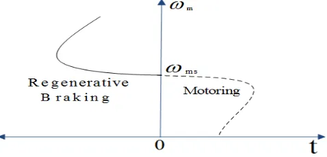
For motoring operation < 90° and for braking operation > 90°. When the speed of the motor is more than the synchronous speed, relative speed between the motor conductors and air gap rotating field reverses, as a result the phase angle because greater than 90° and the power flow reverse and thus regenerative braking takes place. The nature of the speed torque curves are shown in the figure below.
Fig. 1Regenerative Braking of Induction Motor Drives
If the source frequency is fixed then the regenerative braking ofinduction motor can only take place if the speed of the motor is greater than synchronous speed, but with a variable frequency source regenerative braking of induction motor can occur for speeds lower than synchronousspeed. The main advantage of this kind of braking can be said that the generated power is use fully employed and the maindisadvantage of this type ofbraking is that for fixed frequency sources, braking cannot happen below synchronous speeds [5].
III. CLASSICAL DIRECT TORQUE CONTROL STRATEGY
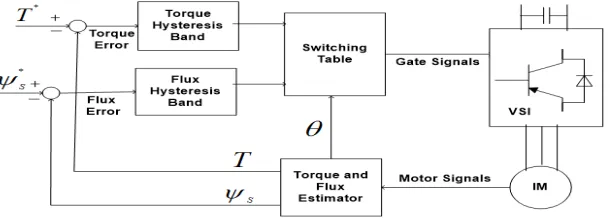
The classical direct torque control strategyis a closed loop control scheme, the important elements of the control structure being: the power supply circuit, a three phase voltage source inverter, the induction motor, the speed controller to generate the torque command and the DTC controller. The CDTC controller again consists of torque and flux estimation block, two hysteresis controllers and sector selection block, the output of the CDTC controller is the gating pulses for the inverter.
from measured motor terminal quantities i.e. stator voltages and current [7]-[9]. An optimal voltage vector for the switching of VSI is selected among the six non-zero voltage vectors and two zero voltage vectors by the hysteresis control of stator flux and torque.
Fig. 2 Block diagram of classical DTC strategy for IM drives
A. TORQUE AND FLUX CALCULATION
This is the simplest method of stator flux estimation, where the machine terminal voltages and currents are sensed and from the stationary frame equivalent circuit the fluxes are computed.
The estimated stator flux is given by the following equations:
= and = −
√ ( + 2 )(2)
= and = −
√ ( + 2 )(3)
= ∫( − ) (4)
= ∫ − (5)
The magnitude of stator flux is given by:
= ( + ( )(6)
Torque is calculated as per below relation:
= − (7)
B. TORQUE AND FLUX CONTROLLER
CDTC of induction motor drives requires two hysteresis controllers. The drive performance is influenced by the width of the hysteresis bands in terms of flux and torque ripples, current harmonics and switching frequency of power electronics devices [10]. Current distortion is reduced by small flux hysteresis band and torque ripple is reduced by small torque hysteresis bands.
= 1 for > + (8)
=−1 for <− (9)
Where 2 is hysteresis bandwidth of the controllers.
= 1 for > + (10)
=−1 for <− (11)
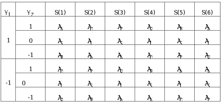
C. SWITCHING SELECTION:
Switching selection is based on , and ( ) is as per below table. Table1 Applied selected voltage vector to inverter
S(1) S(2) S(3) S(4) S(5) S(6)
1
1 0 -1
-1
1 0
-1
IV.SPACE VECTOR MODULATION DTC STRATEGY
In space vector modulation strategy the three phase sinusoidal signals are transformed into a revolving voltage vector with a constant magnitude and angular frequency [11].
The main objectives of space vector pulse width modulation generated gate pulse are the following.
Wide linear modulation range
Less switching loss
Less total harmonic distortion in the spectrum of switching waveform
Easy implementation and less computational calculations
With the emerging technology in microprocessor the space vector modulation has been playing a pivotal and viable role in power conversion (Jenni and Wueest 1993). It uses a space vector concept to calculate the duty cycle of the switch which is imperative implementation of digital control theory of PWM modulators [12]-[16]. Before getting into the space vector modulation theory it is necessary to know about the harmonic analysis of power converters.
Fig. 3 Block diagram of space vector modulation DTC strategyapplied to induction motor
A. IMPLEMENTATION PROCEDURE OF A TWO-LEVEL SPACE VECTOR MODULATION STRATEGY FOR INDUCTION MOTOR DRIVES:
The procedure for implementing a two-level space vector PWM can be summarized as follows: 1. Transform three phase quantities to two phase quantities: ABC to dq
2. Calculate the angle and reference voltage vector based on the input voltage components.
= ( + ) (13)
The phase angle is evaluated from
= (14)
3. Find the sector in which lies, and the adjacent space vectors of V k and V k+1based on the sector angle.
(Where K = 1,2,……….5)
Table2 sector sextant Sector Degrees
1 0 < ≤60
2 60 < ≤120
3 120 < ≤180
4 180 < ≤240
5 240 < ≤300
6 300 < ≤360
5. Find the time intervals , and based on and the angle ( ).
= + (15)
= ( )
( ) (16)
= ( )
( )(17)
= −( + ) (18)
ℎ
= =
and , and are dwell times for the vectors , and respectively [18].
V. SIMULATION RESULTS AND DISCUSSION
Induction motor drive model is simulated as per parameters given in below:
Nominal Power = 150 KW,Rated Torque = 955 N,Stator voltage = 460 V,Frequency = 50 HZ Stator Resistance = 14.85 mStator Leakage Inductance = 0.3027 mH,Rotor Resistance = 9.295 mΩ
Rotor Leakage Inductance = 0.3027 mH,Mutual Inductance = 10.46 mH
A. SIMULATION MODEL OF CLASSICAL DTC STRATEGY
Fig.4 Simulink Model of Classical DTC
B. SIMULATION MODEL OF SPACE VECTOR MODULATIONDTC STRATEGY
In the simulinkmodel of space vector modulation DTC strategy the reference torque and flux both are calculated from the induction motor speed. There are flux and torque PI controller to compensate the steady state error and to produce the decoupling effect between torque and flux.IGBT switches are controlled by space modulation strategy.
Fig.5 Simulink Model of Space Vector Modulation DTC
C. SIMULATION RESULTS OF CLASSICAL DTC STRATEGY
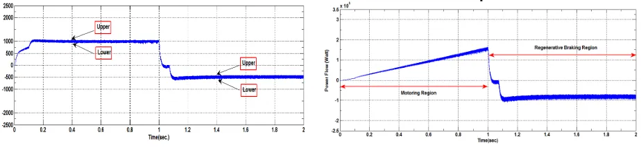
Fig. 6 Stator Currents in Classical DTC Fig. 7 Speed in Classical DTC
Initially stator currents of induction motors are more than the steady state currents, this condition occurs due to inductance of the induction motor. Speed is varying linearly upto 1 second after that it is more than the synchronous speed i.e. (1500rpm) for regenerative braking.
Fig.8 Torque in Classical DTC Fig.9 Power Flow in Classical DTC Torque and power flow both are positive in forward motoring region and negative in the regenerative braking region. Power flow in the regenerative braking is from load to source side.
Reference to theFig.8torque ripple for motoring and regenerative braking mode is calculated as below: Peak to peak torque ripple in motoring mode (0 to 1 second) = 1080-910
= 170 N-m. (19) Regenerative mode peak to peak torque ripple =(-400)-(-600)
= 200 N-m. (20)
D.SIMULATION RESULTS OF SPACE VECTOR MODULATION DTC STRATEGY
Speed variation for space vector modulation DTC is same as the classical direct torque control strategy, Because of inputs applied to the speed control unit are same for both strategies.
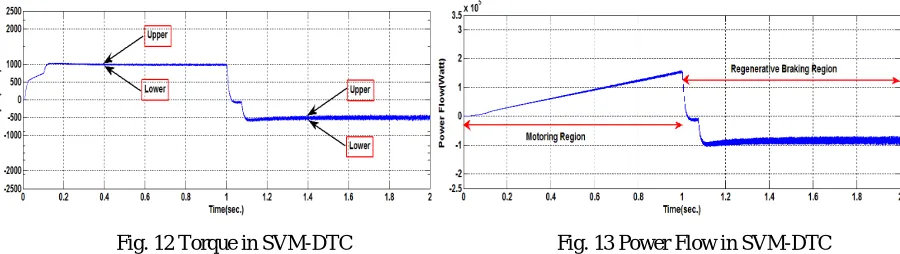
Fig. 12 Torque in SVM-DTC Fig. 13 Power Flow in SVM-DTC
Reference to Fig.13, between time 0 to 1 seconds drive is operating in motoring mode and in the time range 1 to 2 seconds drive is operating in the regenerative braking mode.Power flow in the motoring mode is positive and negative for regenerative braking mode.
Torque ripple reference to the Fig.12 is calculated as following: Peak to peak torque ripple in motoring mode (0 to 1 second) =1040-950
= 90 N-m. (21) Regenerative mode peak to peak torque ripple =(-460)-(-564)
= 104 N-m. (22)
Henceaccording to relation (19)-(22) toque ripple in SVM-DTC is reduced as compared to the classical DTC for both motoring and regenerative braking region. Hence it can be observed that space vector modulation DTC strategy is superiorthanthe classical DTC strategy.
VI.CONCLUSIONS
In this paper, regenerative braking of induction motor drive is explained with the help of simulation results for classical and space vector modulation strategies. Following conclusions are derived from simulink results:
(1) Inverter switching frequency is variable in the classical DTC due to presence of the hysteresis controller, space vector modulation DTC strategy provides the constant switching frequency.
(2)It is realized that induction motor drive operation under the space vector modulation direct torque control strategy gives reduced torque ripple as compared to classical direct torque control strategy for the entire load and speed range. (3)In the classical direct torque control strategy a single voltage vector is applied during one sampling time, for space vector modulation direct torque control strategy a sequence of the six vectors is applied during the same time. This is the merit of space vector modulation direct torque control strategy due to reduced harmonics.
REFERENCES
[1] B.K.Bose, “Modern Power Electronics and AC Drives” Prentice-Hall, 2005.
[2] G.K Dubey “Fundamentals of electrical drives” Narosa Publishing House Second Edition 2001 Fifty Eight Reprint 2014.
[3] Ion Boldea, Cristian Lascu and Frede Blaabjerg “A modified direct torque control for induction motor sensorless drive”IEEETransactions on Industry Applications, vol. 36, no. 1, January/February 2000.
[4] Jun-Koo Kang,“New direct torque control of induction motor for minimum torque ripple and constant switching frequency”IEEE Transactions On Industry Applications, vol. 35, no. 5, September/October 1999.
[5] Giuseppe Buja and Roberto Menis “Steady-state performance degradation of a dtc im drive under parameter and transduction errors”IEEE Transactions On Industrial Electronics, vol. 55, no. 4, April 2008.
[7] Francesco Profumo “FOC and DTC: Two viable schemes for induction motors torque control”IEEE Transactions on Power Electronics, vol. 17, no. 5, September 2002.
[8] M. A. Jabbar, Ashwin M. Khambadkone and Zhang Yanfeng “Space-vector modulation in a two-phase induction motor drive for constant-power operation”IEEE Transactions On Industrial Electronics, vol. 51, no. 5, October 2004.
[9] Tole Sutikno “An optimized switching strategy for quick dynamic torque control in dtc-hysteresis based induction machines” IEEE Transactions On Industrial Electronics, vol. 58, no. 8, August 2011.
[10] Zhifeng Zhang, Renyuan Tang, Baodong Bai and Dexin Xie “Novel direct torque control based on space vector modulation with adaptive stator flux observer for induction motors.IEEE Transactions On Magnetics, vol. 46, no. 8, August 2010.
[11] Giovanni Serra, Domenico Casadei, Angelo Tani, Luca Zarri, and Francesco Profumo “Performance analysis of a speed-sensorless induction motor drive based on a constant-switching-frequency dtc scheme”IEEE Transactions On Industry Applications, vol. 39, no. 2, March/April 2003.
[12] Thomas G. Habetler, Francesco Profumo, Michele Pastorelli, and Leon M. Tolbert, “Direct torque control of induction machines using space vector modulation” IEEE Transactions On Industry Applications, vol. 28, no. 5, September / October 1992.
[13] Paul C. Krause, Oleg Wasynczuk and Scott D. Sudhoff “Analysis of Electrical machinery and drive systems second edition IEEE.
[14] G. Narayanan and V.T. Ranganathan “Aalytical evoluation of harmonic distortion in pwm ac drives using the notion of stator flux ripple” IEEE Transation On Power Electronics vol. 20(2), pp. 466-474, Mar. 2005.
[15] Peter Vas “Sensorless vector and direct torque control” Oxford Science Publication.
[16] Tae-Woong Yoon “Speed-sensorless dtc-svm for matrix converter drives with simple nonlinearity compensation” IEEE Transactions On Industry Applications, vol. 43, NO. 6, November/December 2007.
[17] Giuseppe Buja and Roberto Menis “Steady-state performance degradation of a dtc im drive under parameter and transduction errors” IEEE Transactions On Industrial Electronics, vol. 55, no. 4, April 2008.
[18] M. A. Jabbar, Ashwin M. Khambadkone and Zhang Yanfeng “Space-vector modulation in a two-phase induction motor drive for constant-power operation” IEEE Transactions On Industrial Electronics, vol. 51, no. 5, October 2004.
BIOGRAPHY
Pradeep Kumar Yadav was born in Faizabad, India in 1991. He completedhis M.Tech degree in electrical engineering with specialization in power electronics and drives from Kamla Nehru Institute of Technology Sultanpur, affiliated to Dr. A. P. J. Abdul Kalam Technical University, Lucknow, Uttar Pradesh India.