Power Quality Improvement in 3-Phase
4-Wire Distribution System Using Shunt Active
Power Filter
Ram Pratap1, Associate Prof. Padmesh Singh2, Ubaidullah3
Site Engineer, M. Tech (BBDU), Lucknow, UP, India1
Associate Professor, Head Incharge, Dept of Electrical Engg., BBDNIIT, Lucknow, UP, India2 P G Scholar, Dept of Electrical Engg, BBDU, Lucknow, UP, India3
ABSTRACT: In the recent decades, the world has seen an expansion in the use of non-linear loads. These loads draw
harmonic non-sinusoidal currents and voltages in the connection point with the utility and distribute them through it. The propagation of these currents and voltages into the grid affect the power systems in addition to the other clients’ equipments. Active power filters have been proposed as efficient tools for power quality improvement and reactive power compensation. The different traditional and modern harmonic solutions topologies are presented. The use of SAPF for harmonic current and total harmonics distortion had been studied for unbalanced three phase four wire system. Self-Tuning Filter for the improvement of the SAPF’s efficiency in the case of distorted and unbalance voltage system is presented and discussed. This new control concept is demonstrated with extensive MATLAB/Simulink simulation studies and validated through digital signal processor-based results and are tabulated and discussed. . The simulation results confirm the improvement of the quality of energy, by maintaining the THD of the source current after compensation below 5%the harmonics limit imposed by the IEEE-519 standard.
I. INTRODUCTION
The electric power system is considered to be composed of three functional blocks -generation, transmission and distribution. For a reliable power system, the generation unit must produce adequate power to meet customer’s demand, transmission systems must transport bulk power over long distances without overloading or jeopardizing system stability and distribution systems must deliver electric power to each customer’s premises from bulk power systems. Distribution system locates the end of power system and is connected to the customer directly, so the power quality mainly depends on distribution system. The reason behind this is that the electrical distribution network failures account for about 90% of the average customer interruptions. In the earlier days, the major focus for power system reliability was on generation and transmission only as these more capital cost is involved in these. In addition their insufficiency can cause widespread catastrophic consequences for both society and its environment. But now a day’s distribution systems have begun to receive more attention for reliability assessment.
Initially for the improvement of power quality or reliability of the system FACTS devices like static synchronous compensator (STATCOM), static synchronous series compensator (SSSC), interline power flow controller (IPFC), and unified power flow controller (UPFC) etc are introduced. These FACTS devices are designed for the transmission system. But now a days more attention is on the distribution system for the improvement of power quality, these devices are modified and known as custom power devices. The main custom power devices which are used in distribution system for power quality improvement are distribution static synchronous compensator (DSTATCOM), dynamic voltage Restorer (DVR), active filter (AF), unified power quality conditioner (UPQC) etc.
The energy distributers as like as consumers was then concerned by imposing some regulations protecting against the expansion of harmonic problem. Many regulations concerning the harmonic emissions has been proposed by the international electrical committee’s like IEC-61000 and by the recommendations IEEE Std. 519-92 [1, 2].
The consumption of reactive power in industrial and domestic loads presents also an important issue in the discussion of power quality problems. The reactive power consumed by non-resistive loads causes higher RMS current values in addition to extra heating of power transmission and distribution systems. The use of batteries of capacitors or synchronous machines for local reactive power production has been proposed for a long time. The accelerated development of power electronics and semiconductor production had encouraged the use of STATIC VAR compensators for the reactive power compensation. However, these solutions looks inefficient and can cause extra problems in power systems in the case of high current and voltage harmonic emissions. The fact that these systems are especially designed to compensate the fundamental based reactive power, in addition to high possibilities of interaction between these compensation elements and system harmonics make it unstable solutions in modern technologies.
In order to face the problem of harmonics, many solutions has been proposed. These solutions included modifications on the load itself for less harmonic emissions like the case of special structure single phase and three phase rectifier, and PWM rectifiers. Or the connection on the polluted power grids of other traditional or modern compensation systems.
Most of traditional harmonic reduction solutions includes the use of harmonic trapping passive filters based on RLC elements calculated in accordance with the harmonic ranges has been trapped. In addition, these passive filters could be designed to compensate the reactive power simultaneously with the desired harmonics. Nevertheless, these solutions are of poor efficiency due to different factors.
II POWER QUALITY ISSUE AND SYSTEM DESCRIPTION
Power quality is “the provision of voltages and system design so that the user of electric power can utilize electric energy from the distribution system successfully without interference or interruption.” A broad definition of power quality borders on system reliability, dielectric selection on equipment and conductors, long-term outages, voltage unbalance in three-phase systems, power electronics and their interface with the electric power supply and many other areas .
Electric systems and grids are complex dynamic systems. These systems suffer usually from unexpected or sudden changes of the currents and voltages. These changes are due to mainly the different types of linear and non-linear loads which they are connected. In addition, to different types of accidents which can intervener into the grid [3]. With the increasing use of power semiconductor devices in the most of industrial and domestic procedures, the electric grids is polluted with different harmonic currents and voltages. These harmonics affect the normal function of the most of the grid connected devices; in addition to considerable economic losses. Many classic and modern solutions have been proposed in the literary for the harmonic problems. In this chapter ,we discuss the harmonic problem as one of the most common power quality problems will be presented. The different modern and traditional solutions will then be discussed.
Power quality in electric networks is one of today's most concerned areas of electric power system. The power quality has serious economic implications for consumers, utilities and electrical equipment manufacturers. Modernization and automation of industry involves increasing use of computers, microprocessors and power electronic systems such as adjustable speed drives. Integration of non-conventional generation technologies such as fuel cells, wind turbines and photo-voltaic with utility grids often requires power electronic interfaces. The power electronic systems also contribute to power quality problems (generating harmonics).
Under the deregulated environment, in which electric utilities are expected to compete with each other, the customer satisfaction becomes very important. The impact of power quality problems is increasingly felt by customers - industrial, commercial and even residential.
III SHUNT ACTIVE POWER FILTER
The SAPF, also called pure active filter, meets overall specifications and constitutes the optimal harmonic filtering solution as it is viable and cost-effective for low to medium kVA industrial loads where system engineering effort is a large part of overall cost. This system does not create displacement power factor problems and utility loading. Moreover supply side inductance Ls does not affect the harmonic compensation capability of parallel active filter system, controlled as a harmonic current source. The SAPF can damp harmonic propagation in a distribution feeder or between two distribution feeders , controlled as a harmonic current source its performance is not affected by supply voltage harmonics.
Shunt active power filter compensates current harmonics by injecting equal-but-opposite harmonic compensating currents into the grid. In this case the shunt active power filter operates as a current source introducing the harmonic components generated by the load but phase difference by 180° [8]. This principle is applicable to any type of load considered as harmonic source. Moreover, with an appropriate control scheme, the active power filter can also compensate the load power factor. In this way, the power distribution system sees the non-linear load and the active power filter as an ideal resistor. The current compensation characteristics of the shunt active power filter is shown in Figure 3.
Figure 1 : Compensation characteristic of shunt active power filter
The SAPF, also called pure active filter, meets overall specifications and constitutes the optimal harmonic filtering solution [4] as it is viable and cost-effective for low to medium kVA industrial loads where system engineering effort is a large part of overall cost. This system does not create displacement power factor problems and utility loading. Moreover supply side inductance Ls does not affect the harmonic compensation capability of parallel active filter system, controlled as a harmonic current source. The SAPF can damp harmonic propagation in a distribution feeder or between two distribution feeders [5], controlled as a harmonic current source its performance is not affected by supply voltage harmonics. Figure shows the basic circuit diagram of a pure shunt active filter. It should be connected in parallel as close as possible to a harmonic-producing load. The power circuit of the SAPF consists of a three phase Voltage-Source PWM Inverter (VSI), using the IGBTs, coupled at the Point of Common Coupling (PCC) via an output ac filter (L, LC, LCL) and a dc capacitor, generally considered as an energy storage element. The control circuit is usually based on a modern digital controller using DSPs, FPGAs, etc
Modeling of Active Power Filter
Figure 2 : SAPF connection to the PCC
The SAPF are connected in parallel with the harmonic producing loads. They are expected to inject in real time the harmonic currents absorbed by the pollutant loads. Thus, the grid current will become sinusoidal.
IV DESIGN AND CONTROL SCHEME OF SHUNT ACTIVE POWER FILTER
The quality of electrical power is one of the major growing concerns for utility as well as consumers. The increasing use of non linear and poor power factor loads such as Power electronic converters, Arc furnace, Adjustable speed, uninterruptable power supplies etc. are the responsible factor for the power quality issues. The most important factors of poor power quality are harmonics and high neutral current. Poor power quality factors such as switching phenomena results in oscillatory transients in the electrical supply, connection of high power non-linear loads contributes to the generation of current and voltage harmonic components, voltage sags are generated due to the high economical losses, short-term voltage drops (sags) can trip electrical drives or more sensitive equipment, leading to costly interruptions of production etc.
In this dissertation an overview of design parameters of a SAPF is presented and analyzed. Since the increase in the value of the DC voltage improves the controllability of the active filter and knowing that the choice of this voltage is reflected in large part on the choice of switches, the Vdc value continues to be chosen as the greatest voltage respecting the switches. The inductor value is an optimal one taking the HF filtering and harmonics injection in consideration. A reduction in the value of the capacity will cause a significant increase ripple voltage.
However, the modification of Cdc can have a serious impact on the variation of ΔVdc during load transients creating
voltage drop that can negatively affect the controllability of current compensation The design of these components is based on the following assumptions:
(a). The source voltage is sinusoidal
(b). To design the Lf ac side line current distortion is assumed to be 5% (c). There is fixed capability of reactive power compensation of the active filter
(d). The PWM converter is assumed to operate in the linear modulation mode (0≤ma≤1).
(e). The switching frequency is selected in function of the highest order of harmonic to be compensated. Theoretically it is possible to control the harmonics up to half the switching frequency to be compensated.
The controlling of shunt Active Power Filter is done by Active Current Component, Hysteresis Control Method.
A. Active Current Component Theory
Ua=sin(θ)
Ub= sin(θ-2π/3)
Uc= sin(θ+2π/3) (1)
Error current can be calculated as
Ierr = I*-I (2)
The actual dc-link voltage is sensed and passed through a first-order low pass filter (LPF) to eliminate the presence of switching ripples on the dc-link voltage and in the generated reference current signals. The difference of this filtered dc-link voltage and reference dc-link voltage is given to a discrete- PI regulator to maintain a constant dc-link voltage under varying generation and load conditions. The dc-link voltage error at seventh sampling instant is given as:
Vdcerr(n)=V*dc(n)-Vdc(n) (3)
Figure 3: Block diagram representation of grid-interfacing inverter control.
The duty ratio of inverter switches are varied in a power cycle such that the combination of load and inverter injected power appears as balanced resistive load to the grid. The regulation of dc-link voltage carries the information regarding the exchange of active power in between renewable source and grid. Thus the output of dc-link voltage regulator results in an active current The multiplication of active current component with unity grid voltage vector templates generates the reference grid currents. The reference grid neutral current is set to zero, being the instantaneous sum of balanced grid currents. The grid synchronizing angle obtained from phase locked loop (PLL) is used to generate unity vector template. The PLL circuit tracks continuously the fundamental frequency of the load current. The design of the PLL circuit should allow proper operation under high distorted and unbalanced load currents. An interesting design of PLL circuit, that is almost insensitive to unbalances and distortions. This synchronizing circuit (PLL circuit) determines quickly the frequency and phase angle of the fundamental positive-sequence component of the measured load currents ia, ib, and ic. Inputs are iab = ia – ib and icb = ic – ib. This circuit has proved to be very effective, even under very high distorted and/or unbalanced input waveforms.
B. Hysteresis Current Control Method
Because of advances in solid state power devices and microprocessors, switching power converters are used in more and more modern motor drives to convert and deliver the required energy to the motor. The energy that a switching power converter delivers to a motor is controlled by Pulse Width Modulated (PWM) signals
applied to the gates of the power transistors. PWM signals are pulse trains with fixed frequency and magnitude and variable pulse width. There is one pulse of fixed magnitude in every PWM period. However, the width of the pulses changes from pulse to pulse according to a modulating signal. When a PWM signal is applied to the gate of a power transistor, it causes the turn on and turn off intervals of the transistor to change from one PWM period to another PWM period according to the same modulating signal. The frequency of a PWM signal must be much higher than that of the modulating signal, the fundamental frequency, such that the energy delivered to the motor and its load depends mostly on the modulating signal
sine PWM (SPWM) technique. The utilization rate of traditional sine PWM technique is only 78.5 % of DC bus voltage.
Another technique which is widely used is hysteresis band current controller because of its simplicity. This method has uses fast response of current loop. Another advantage is that it does not need any knowledge of load parameters. But it has disadvantage that switching frequency is irregular.
One of the simplest current control PWM techniques is the hysteresis band (HB) control shown in this figure 4. Basically, it is an instantaneous feedback current control method in which the actual current continuously tracks the command current within a pre assigned hysteresis band. As indicated in the figure 4.2, if the actual current exceeds the HB, the upper device of the half-bridge is turned off and the lower device is turned on. As the current decays and crosses the lower band, the lower device is turned off and the upper device is turned on. If the HB is reduced, the harmonic quality of the wave will improve, but the switching frequency will increase, which will in turn cause higher switching losses.
This same logic can applied to three phase waveform also. In three phase 3 reference signal 120 phase shifted is used and is compared with load current as a result we get desired output. Advantage and disadvantage of this method is shown below.
Advantages:
1. Excellent dynamic response. 2. Low cost and easily implementation. Disadvantages:
1. Large current ripple in steady state. 2. Variation of switching frequency.
3. No intercommunication between each hysteresis controller of three phases and hence no strategy to generate zero voltage vector. Hence signal will leave hysteresis band whenever zero vector is turn on.
4. The modulation process generates sub harmonic components
The current control strategy plays an important role in fast response current controlled inverters such as the active power filters. The hysteresis current control method is the most commonly proposed control method in time domain. This method provides instantaneous current corrective response, good accuracy and unconditioned stability to the system. Besides that, this technique is said to be the most suitable solution for current controlled inverters.
Hysteresis current control is a method of controlling a voltage source inverter so that an output current is generated which follows a reference current waveform [9].
The basic structure of PWM voltage source inverter with hysteresis controller is shown in Figure 2. The hysteresis control strategy aims to keep the controlled current inside a defined rejoin around the desired reference current. The status of the switches is determined according to the error. When the current is increasing and the error exceeds a certain positive value, the status of the switches changes and the current begins to decrease until the error reaches a certain negative value, then the switches status changes again.
Figure 4 : Hysteresis control principle
frequency is the major draw-back of this method [4, 9]. This variable frequency affects mainly the function of power electronic elements which can’t support high switching frequency in high power applications. In order to solve the problem of variable switching frequency, a new hysteresis control strategies like “modulated hysteresis control” and “variable hysteresis band” were proposed. In the modulated hysteresis control it is difficult to define the hysteresis band width. Over more, the fix switching frequency achieved using this method affects the rapidity obtained by hysteresis control [4].
Although the likelihood of harmonic problems is very low, the cases in which they do occur can result in decreasing power system reliability. An understanding of the causes, potential effects and mitigation means for harmonics can help to prevent harmonic related problems at the design stage and reduce the probability of undesired effects occurring on start-up. It should be kept in mind that if the harmonic producing loads are small in relation to the total plant load, then harmonics are not an issue. When the non-linear loads become a substantial portion of the total load, it becomes worthwhile to give some consideration to harmonics. In these cases, harmonic modelling analysis is recommended to predict harmonic levels and identify potential resonance problems regardless of the rectifier pulse number.
V.MODELLING AND SIMULATION
In the last two sections, different topologies and control methods of Shunt Active Power Filter (SAPF) were presented and discussed. These methods include the harmonic contents extraction from one part, and the control of SAPF from the other part. Different direct and indirect methods were presented and discussed. The control schemes of these methods were also presented. Simulation is the imitation of the operation of a real world system over time. It involves the generation of an artificial history of the system and the drawing of inferences from it.
Advantages of Simulation Building consensus. Preparing for change. Cost effective investment. Training aid capability. Specification of requirements Disadvantages of Simulation
Interpretation of results required Time consuming skill oriented.
Inappropriately used Training required
This presents the simulation results of models discussed in this work in addition to different parameters of grid and filter. The simulation results are shown and discussed. Different grid conditions will be discussed and results will be compared. The comparison includes the extraction methods, VSI control theories, DC voltage control, in addition to the function under non ideal system conditions and the use of Self Tuning Filter (STF) for non ideal system.
The simulated system is a three phase balanced and non-balanced voltage system, the non-linear load used in this work is a three phase non controlled universal bridge rectifier discussed in the previous chapters. Another important thing in simulation is powergui, it is graphical user interface for the analysis of circuits and systems. The Powergui block opens a graphical user interface (GUI) that displays steady-state values of measured current and voltages as well as all state variables (inductor currents and capacitor voltages). The Powergui block allows you to modify the initial states in order to start the simulation from any initial conditions. It allows load flow computation and initialization of three phase networks containing machines. The Powergui block also displays impedance versus frequency plots when Impedance Measurement blocks are present in your model. If you own the Control System Toolbox, the Powergui block can generate the state-space model (SS) of your system and automatically opens the LTI Viewer interface for time and frequency domain responses. Copy the Powergui block in the top level of your model and double-click on the block to open the interface.
Display and modify initial state values Perform load flows and machine initialization Display impedance vs frequency measurements Use the LTI Viewer of the Control System Toolbox Generate a report of the steady-state calculations
VI.RESULTS
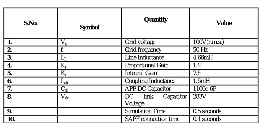
All control schemes used in SAPF is shown in model. Their parameters values are tabulated as below.
TABLE I
PARAMETERS OF THE ANALYZED SYSTEM
S.No.
Symbol
Quantity
Value
1. Vg Grid voltage 100V(r.m.s.)
2. f Grid frequency 50 Hz
3. LL Line Inductance 4.66mH
4. Kp Proportional Gain 1.9
5. Ki Integral Gain 7.5
6. Lsh Coupling Inductance 1.5mH
7. Cdc APF DC Capacitor 1100e-6F
8. Vdc DC link Capacitor
Voltage
283V
9. Simulation Time 0.5 seconds
10. SAPF connection time 0.1 seconds
The THD of the line current is reduced to permissible limit (below 5%) after using the SAPF. The THD figure of the FFT window is shown below.
Figure: 5 THD of phase a with SAPF
Figure: 6 THD of phase b with SAPF
In above FFT (Fast Fourier Transform) window we can see THD is equal to 4.67 % for phase b, and in this case 2nd (even) and 5th (odd)harmonics are more dominating in the system.
Figure: 7 THD of phase c with SAPF
In above FFT (Fast Fourier Transform) window we can see THD is equal to 4.33 % for phase c, and in this case again 2nd (even) and 5th (odd)harmonics are more dominating in the system.
From above three analyses we see that the THD of line current of all three phases is very much reduced below desired level (below5%). The Shunt Active Power Filter can do this in a very efficient way. By reducing the THD it also reduces the neutral current and makes the power factor unity.
TABLE II
S.No. THD
THD without
SAPF
Dominating frequencies
without SAPF
Reduced THD
with SAPF
Dominating frequencies with SAPF
1. Phase
a 20.27% 5
th
and 7th 4.49% 2nd and 3rd
2. Phase
b 20.22% 5
th
and 7th 4.67% 2nd and 5th
3. Phase
c 14.18% 5
th
In this paper we have analyzed the three phase four wire distribution system and point out the problems associated due to use of unbalanced non- linear loads. By the use of SAPF we have reduced current harmonics of the system which is shown in table. It also improves power factor and reduces neutral current which make system stable. The simulation results confirm the improvement of the quality of energy, by maintaining the THD of the source current after compensation well below 5%, the harmonics limit imposed by the IEEE-519 standard. Even harmonics can be created in rectifier systems by firing timing irregularities. Symmetry makes the Fourier coefficients of even order harmonics to
zero. Harmonics bred from loads are mainly odd order because the current waveforms have half-wave symmetry. Since
the even harmonics are negligibly small, they generally are not measured in electric power systems.
VI. CONCLUSION AND FUTURE SCOPE
The work was set out to explore the concept to improve power quality in distribution system. The main facts findings are chapter specific and were summarized within the respective chapters of dissertation. This work has presented a novel control of an existing grid interfacing inverter to improve the quality of power at PCC for a 3-phase 4-wire system. It has been shown that the grid-interfacing inverter can be effectively utilized for power conditioning without affecting its normal operation of real power transfer. This approach thus eliminates the need for additional power conditioning equipment to improve the quality of power. Extensive MATLAB/Simulink simulation as well as the DSP based experimental results have validated the proposed approach and have shown that the grid-interfacing inverter can be utilized as a multi-function device.
These control strategies tested on different sets of loads to predict the performance of shunt active power filter. In Active Current Component Theory, DC capacitor voltage is used to generate reference currents. The regulation of the capacitor voltage carries the information of reactive power exchange between SAPF and load. Performance of shunt active power filter is verified with the simulation results.
The studies shows that the parallel active power filters represent an efficient solution for the compensation of harmonics produced by the non- linear loads. The performance of active power filter depends not only on the choice of its power circuit, but also on the used control strategy.
The control of SAPF based on PI controllers in three-phase, two stationary phases, and synchronous reference system has been studied and discussed. Because of its simple structure, PI controllers have been used for the control of filter currents and its DC voltage, the simulation results shows that it offers a very good performance and stability.
Harmonic distortion is increasing day by day at a faster rate and is a matter of concern to the utility, customer and manufacturers of different equipment. To keep the harmonic distortion to low value, following actions are necessary. (a)-In India it is necessary first to create awareness regarding harmonic problems, their effects and elimination techniques among the utility, consumers and manufacturers of different equipments to make power system less polluted.
(b)-The harmonic standards should be imposed on the equipment and should be made mandatory to the manufactures and consumers. The equipment should strictly comply to the harmonic standards before selling it in open market. (c)-The utility should monitor the installation of high tension consumers periodically, regarding the harmonic distortion and penalties should be imposed on customers using equipments crossing specified limits.
(d)-Filters should made compulsory to High Tension Line (H.T.) consumers.
REFERENCES
[1] Dharmendra Gour, Devendra Dohare, Abhishek Saxena,” A study of various filters for powe quality improvement.” International Journal of Advanced Research in Electical, Electronics and Instrumentation Engineering (IJAREEIE), vol. 4, issue 1, pp 138-143, January 2015. [2] Sai Kiran Kumar Sivakoti, Y.Naveen Kumar, D. Archana,” Power quality improvement in distribution system using DSTATCOM in
transmission lines.” Sept/Oct 2011.
[3] C. Sharmeela, M. R. Mohan, G. Uma, J. Baskaran et A.C. College, Fuzzy Logic Controller Based Three-Phase Shunt Active Filter for Line Harmonics Reduction, Univ Anna, Vol. 3, No. 2, pp. 76-80,2007.
[4] IEEE-519, IEEE Recommended Practices and Requirements for Harmonic Control in Electric Power Systems, 1992.
[5] IEC 61000-3-4, Limitations of Emissions of Harmonic Currents Low-voltage Power Supply Systems for Equipment with Rated Current Greater than 16A, 1998.
[6] Leow Pei Ling, SVM Based Hysteresis Current Controller for a Three Phase Active Power Filter, MSc Thesis, Universiti Teknologi Malaysia, 2004.
[7] M. Sc. Mariusz Cichowlas, PWM Rectifier with Active Filtering, Ph. D. Thesis, Warsaw University of Technology, Poland, 2004.
[8] Smruti Ranjan Prusty, FPGA Based Active Power Filter for Harmonics Mitigation, MSc. Thesis, National Institute of Technology Rourkela, India, 2011.
[9] Tan Perng Cheng, A Single-Phase Hybrid Active Power Filter with Photovoltaic Application, Msc. Thesis, Universiti Teknologi Malaysia, 2007.
[10] Abdelmadjid Chaoui, Jean-Paul Gaubert, Fateh Krim, and Laurent Rambault,” IP Controlled Three-Phase Shunt Active Power Filter for Power Improvement Quality‟, IEEE, 1-4244-0136-4/06, pp 2384-2389, 2006.
[11] IlhamiColak, RamazanBayindir, Orhan Kaplan, and FerhatTas, “DC Bus Voltage Regulation of an Active Power Filter Using a Fuzzy Logic Controller”, IEEE Ninth International Conference on Machine Learning and Applications, pp 692-696, 2010.
[12] RongFei, Yu Jingrong, and Luo an, “Reference current computation method based on adaptive low-pass filter for active power filter”, IEEE International Conference on Measuring Technology and Mechatronics Automation, pp 996-999, 2010.
BIOGRAPHY
Ram Pratap He is a site engineer having teaching experience of 2 years in field of digital communication. He got his
B.Tech degree in 2009 and M.Tech degree in 2014 from Babu Banarasi Das University (BBDU),,Lucknow,Uttar Pradesh. His specialization is analog and digital electronics.
Padmesh Singh He is an Associate Professor in Electrical engineering department in Babu Banarasi Das Northern
India Institute of Technology (BBDNIIT), with a teaching experience of 11 years. He got his B.Tech degree in 2005 from Shri Ramswaroop College of Engineering and Management (SRCEM, Dr. A.P.J. Abdul Kalam Technical University, formerly known as UPTU) and M.Tech. degree from Kamla Nehru Institute of Technology, Sultanpur,Uttar pradesh(Dr. A.P.J. Abdul Kalam Technical University, formerly known as UPTU). His specializations are power system and electric machines.
Ubaidullah Received B.Tech. degree from Sagar Institutue of Technology and Management, Barabanki, Uttar Pradesh