University of Twente
EEMCS / Electrical Engineering
Control Engineering
Design of the global software structure and
controller framework for the 3TU soccer robot
Marten Lootsma
MSc report
Supervisors: prof.dr.ir. S. Stramigioli
dr.ir. J.F. Broenink dr. R. Carloni ir. G. van Oort
June 2008
i
Summary
Four identical humanoid soccer robots are currently developed by the three universities of technology in the Netherlands (3TU), with the intention to participate as the TeamDutchRobotics at the RoboCup 2008 competition. In order to move, each robot has 14 joints in its arms and legs, from which 12 are actuated by electric motors. The mechanical configuration is designed for dynamical walking; it is unstable and should continuously have stabilizing control. The ‘brain’ of the robot is a single processor computer, a PC-104 stack. The aim of this master thesis project is twofold:
• Design of the global software structure • Design of the joint controller framework
The first part is about the software architecture, real-time behavior and the use of third-party software. Many software projects do exist for robots, the so-called robot software frameworks. The usability of these frameworks has been investigated, it remained in two candidates for us-ing it in TUlip: Orocos and RoboFrame. However, no framework fully satisfied the require-ments, because Orocos is not light weighted and RoboFrame does initially not support real-time. It has been chosen to use RoboFrame for the non-real-time part of the software and a self-written framework for the real-time part, with kept in mind that RoboFrame later can be ported to support real-time behavior. Furthermore it has been decided to use Linux/Xenomai as operating system to achieve the real-time execution of the software.
The second part is about the design of a software framework for stabilizing controllers: the joint controller framework. The movements of the robot exist of several basic behaviors, such as walking, kicking the ball, stand up etcetera. Each basic behavior might need different config-urations of the joint controllers or even different types of joint controllers. The goal is to create a framework that gives control engineers the opportunity to switch among controllers and to be flexible in adjusting the parameters. The joint controller framework has been designed and a prototype has been realized. Instead of testing it on the real robot, models of the robot have been used to test the framework, because the robot was not assembled yet. Because of prob-lems with the model of TUlip’s body, the joint controller framework is tested on models of a humanoid head as well. The joint controller framework worked well and it has been used for realizing the head demo, as described in Visser (2008).
For future work, the prototype of the joint controller framework has to be extended to support switching between controllers while performing movements. It is expected that switching of controllers require an initialization mechanism for the new controllers in order to perform the transition of the controllers as smooth as possible.
Instead of having two separate frameworks for TUlip, it is an option to port RoboFrame to sup-port real-time behavior, in order to create a light weight real-time framework that can be used for the whole system.
Samenvatting
Vier identieke humanoid voetbal robots worden op dit moment ontwikkeld door de drie Neder-landse technische universiteiten (3TU), met de intentie om als de TeamDutchRobotics aan de RoboCup 2008 competitie mee te doen. The robots hebben elk 14 gewrichten in de armen en benen, waarvan 12 geactueerd door elektrische motoren. Het mechanische ontwerp is toege-spitst op dynamisch lopen; het is onstabiel en heeft voordurend stabiliserende regelactie nodig. Het ‘brein’ van de robot is een computer met een enkele processor, een PC-104 stack. Het doel van deze master opdracht kan worden verdeeld in twee gedeelten:
• Ontwerpen van de globale software structuur • Ontwerpen van de joint controller framework
Het eerste gedeelte gaat over de software architectuur, real-time gedrag en het gebruik van soft-ware van derden. Er zijn veel softsoft-ware projecten speciaal voor robots beschikbaar, de zoge-naamde robot software frameworks. Het nut van het gebruik van deze frameworks is onder-zocht. Het resulteerde in twee kandidaten voor het gebruik in TUlip: Orocos en RoboFrame. Alhoewel, geen van beide frameworks voldoet volledig aan de eisen, omdat Orocos waarschi-jnlijk een te zware belasting voor de processor is en RoboFrame ondersteund geen real-time gedrag. Het is gekozen om RoboFrame te gebruiken voor het niet real-time gedeelte van de soft-ware en om een zelf geschreven real-time framework te gebruiken voor de tijdkritische softsoft-ware gedeelten, met de gedachten dat RoboFrame later kan worden aangepast om real-time gedrag te ondersteunen.
Het tweede gedeelte gaat over het ontwerp van een software framework voor stabiliserende regelaars: de joint controller framework. De bewegingen van de robot bestaan uit verschil-lende basic behaviors, zoals lopen, tegen een bal schoppen, opstaan etcetera. Elke van die basic behaviors heeft wellicht een andere configuratie van regelaars of zelf verschillende type regelaars nodig. Het doel is om een framework te creëren dat regeltechnici de mogelijkheid geeft om van regelaars te wisselen en om flexibel te zijn met het aanpassen van parameters. De joint controller framework is ontworpen en een prototype is gerealiseerd. Omdat de mecha-nische constructie van de robot nog niet volledig af was, is het framework getest op modellen van de robot. Door problemen met het model van de lichaam van de robot, is het framework ook getest op een model van een humanoid hoofd. Het framework is later gebuikt voor het realiseren van de hoofd demo, als beschreven in Visser (2008).
Voor verder werk, de prototype van the joint controller framework moet worden uitgebreid om tijdens het bewegen van de robot het verwisselen van regelaars te ondersteunen. Het is te verwachten dat een initialisatie mechanisme nodig is om de transitie naar nieuwe controllers zo geleidelijk mogelijk te laten verlopen.
In plaats om twee verschillende frameworks voor TUlip te gebruiken, is het een optie om RoboFrame aan te passen om real-time gedrag te ondersteunen, zodat een framework kan worden gebruikt voor het gehele systeem.
iii
Preface
With this report I conclude my Master’s program in Electrical Engineering. Doing the Master’s program has been a great addition to my HBO education. I am very thankful that I had the opportunity to do so.
First of all I want to thank my parents that they always believed in me and for their support. They made me who I am and they make me feel proud.
In general I want to thank the people of the Control Engineering group. It has been a great experience to participate with them in several interesting projects. I would like thank Rafaella Carloni, without her help this report could not be finished in time. I owe thanks to Gijs van der Hoorn from the University of Delft for his cooperation and interesting ideas.
I want to thank my fellow students and friends Harm de Boer, Hans van der Steen, Jeroen War-nas and Rein Hoekema for being with me this three years. I owe special thanks to Harm for being critical on how to document my work.
Last but not least, I want to thank my better half: Alfiya Lootsma. Thanks for standing by me and for your unlimited support and patience.
Contents
1 Introduction 1
1.1 The TUlip project . . . 1
1.2 Assignment . . . 1
1.3 Approach . . . 1
1.4 Report outline . . . 2
2 Background 3 2.1 Configuration of TUlip . . . 3
2.2 Software in similar robots . . . 4
2.3 Robot software frameworks and middleware . . . 4
3 Software architecture analysis 5 3.1 Requirements . . . 5
3.2 Functional specification . . . 5
3.3 Functions mapped on layered structure for priorities . . . 7
3.4 Conclusions . . . 8
4 Software framework analysis 9 4.1 Comparison of third-party robot software frameworks . . . 9
4.2 Software framework choice for TUlip . . . 11
4.3 Real-time operating system . . . 11
4.4 Conclusions . . . 12
5 Analysis of joint controller organization 13 5.1 Multiple controller configurations . . . 13
5.2 Principle of control objects . . . 14
5.3 Conclusions . . . 16
6 Design and implementation of the joint controller framework 17 6.1 Time driven tasks with data storages . . . 17
6.2 Execution of the control objects . . . 18
6.3 Implementation . . . 19
6.4 Discussion on the extension of features . . . 20
6.5 Conclusions . . . 21
7 Realization of test setups and control configurations 22 7.1 Implementation of the control objects . . . 22
CONTENTS v
7.3 Test setup . . . 23
7.4 Results . . . 25
7.5 Conclusions . . . 26
8 Conclusions and recommendations 27 8.1 Conclusions . . . 27
8.2 Recommendations . . . 27
A Robot software framework to use for TUlip 29 A.1 Requirements for a robot software framework for TUlip . . . 29
A.2 Evaluation available frameworks . . . 30
A.3 Orocos versus RoboFrame . . . 31
A.4 Conclusion . . . 33
B Real-time module 35 B.1 Timing measurements of the tasks . . . 35
B.2 Model-in-the-loop . . . 35
C Timing test of a task running on Xenomai 37
1
1 Introduction
1.1 The TUlip project
TUlip is the Dutch Robotics soccer robot, which is a common project of the three technical uni-versities of the Netherlands (3TU). It is a humanoid robot, whose body structure resembles that of a human. The goal of the Dutch Robotics Team is to participate in the TeenSize Humanoid League of RoboCupSoccer 2008 in China, an annual soccer competition for robots, where the TeenSize Humanoid League is a category for autonomous humanoid robots larger than one meter.
The Dutch Robotics Team consists of four identical robots. They should be able to walk dynam-ically and kick the ball while maintaining balance, processing human-like sensor information, making tactical decisions and communicating among each other.
At the beginning of this master thesis project, the mechanical parts were already designed and in production. The design of the electronics was almost finished as well. However, no decisions about the software had been made yet.
Together with students from Delft, the design and implement of TUlip software had to be real-ized.
1.2 Assignment
The assignment is to participate in the design and the implementation of the robot software architecture. The main point of interest is the implementation of the joint controllers. The aim of the assignment is split into two parts:
• To design a global software architecture and to exploit, if possible, suitable third-party soft-ware in order to realize the designed architecture.
• To design a framework for the joint controllers. The focus of this design is to be as flexible as possible in order to give the control designers the freedom to use and switch between different configurations of controllers.
1.3 Approach
1 The first phase of the assignment is the study on robotics, a survey on software in existing robots and especially how the control of the joints is performed in similar robots.
2 After that, the functions that the software of TUlip should cover had been investigated, and a list of requirement has been set up.
3 In the third phase, the usability of third-party software had been investigated.
• The usability of several third-party software frameworks had been considered. Together with Deen (2008), a test-case has been set up in order to compare two different architec-tures: RoboFrame and Orocos.
• The use of Linux/Xenomai as the real-time operating system had been evaluated.
Together with the project members of the TUlip development team, the decisions have been made.
4 The design and implementation work have been divided over the project members. In the fourth phase of this assignment, the possible controller configurations have been investi-gated and a concept design for the organization of joint controller has been made.
1.4 Report outline
• In Chapter 2, background information on the robot is provided.
• An analysis has been done on the requirement and functions for the software in Chapter 3. A global software architecture will be presented. The different functions of the software are categorized by the layered control structure in order to divide priorities.
• In Chapter 4 several robot software frameworks have been analysed for the usability in TUlip. A suitable robot software framework is suggested and explained. Furthermore the chose is made on which operating system the software will run.
• Chapter 5 describes the analysis of the possible controller configurations and a concept de-sign is made.
• The design and implementation of the joint controller framework is discussed in Chapter 6. • In Chapter 7 the validation of the joint controller framework is discussed.
• Appendix A is the recommendation report on which third-party robot software frameworks are useful to realize the designed software structure.
• Appendix B describes the real-time software abstraction, the timing tests of tasks and how model-in-the-loop is realized.
3
2 Background
In this chapter, background information to support understanding the context of this project is given.
2.1 Configuration of TUlip
The humanoid robot TUlip is about 1.20mhigh and weights, fully assembled, about 14kg. The mechanical configuration is designed for dynamic walking (McGeer, 1988). It is unstable and should continuously have stabilizing control. A rendered picture of the TUlip design is shown in Figure 2.1(a).
In order to move, TUlip has a total of 14 rotational joints in legs and arms, as depicted in Figure 2.1(b). 12 joints are actuated by electrical motors, some of which are constructed asseries elastic actuators(SEA), as described in Williamson (1995).
(a) CAD design (b) Indication of the joints (green boxes with axis)
FIGURE2.1 - The robot TUlip (a) and the simulated model (b)
TUlip should be able to walk dynamically and kick the ball while maintaining balance, pro-cessing human-like sensor information, making tactical decisions and communicating among each other. All these functions are performed by some sort of ‘brain’, which determines au-tonomously the tactical decisions that has to be made. These tactical decisions are based upon information about its environment and status. This information is provided by sensors, such as:
• Pressure sensors in both feet • Acceleration sensors
• Vision system
The tactical decisions are then translated to the necessary movements. To perform these move-ments, the joints need to be actuated. Joint controllers are needed to control this actuation in order to move the initially unstable robot in a proper way. Feedback for joint controllers are provided by rotational position sensors in the joints.
TABLE2.1 - Basic PC104 specifications
Type Specification
Processor low power, fan-less 1.0GHz VIA Eden ULV Work memory 256MB 533MHz DDR2 RAM
Data storage 4GB flash card Communication Gigabit Ethernet
4x USB 2.0 4x Serial port 33MHz PCI Bus
2.2 Software in similar robots
Similar dynamic walking robots have been analysed in order to evaluate the software in existing robots. The main point of interest is the computation of the joint controllers because TUlip has been designed to have a central computer on which the control algorithms of the joint have to be computed as well.
One of these projects is the two dimensional biped Dribbel. Dribbel has been designed at the University of Twente and it is controlled by a distributed network of micro-controllers (Dertien, 2005). A central computer is used, to control all the different distributed micro-controllers. Since the software of Dribbel does not compute the controller at a central computer, the soft-ware implementation of Dribbel is no used.
Flame, a robot of the University of Delft, computes the joint controllers in a central computer. The robot itself is in fact the standard used for the mechanical design of TUlip and therefore similar. The software is a self written set of libraries on a real-time Linux kernel. One thread, timed with the critical time period, processes all the tasks sequentially. So even the non-real-time tasks are performed on the highest frequency which leads to less computational space for the time critical tasks. Flame focuses on implementing a dynamic walking algorithm, while TUlip needs to perform, besides dynamic walking, several other functions. No software of Flame has been used for the implementation of TUlip, however, the software architecture has been studied in order to learn from it.
2.3 Robot software frameworks and middleware
As defined by Douglass (2003): “A framework is a ‘partially completed application that you cus-tomize or specialize for you specific application.’ A framework differs from a library in that a library is a passive thing that you call to invoke a service. A framework is your application that invokes the problem-specific services that you want to perform. Fortunately frameworks for robot software exists.”
As described in Section 2.2, software for similar robots have been developed in previous projects. Since the software in these projects are not reused in TUlip, there are two options:
• write the software from scratch and create a self-written framework, • use a third-party software framework to start with.
5
3 Software architecture analysis
This chapter presents the analysis of software architecture of TUlip. In order to set up a archi-tecture, a list of requirements has been made.
3.1 Requirements
The RoboCup rules, hardware limitations and requests of the control engineers are analysed, and translated to the requirements for the robot software. These requirements are:
• Multiple functions: TUlip should make autonomous decisions, have a vision system, actuate the hardware for performing complex movements (e.g.: dynamic walking), have stabilizing control and communicate with team members and the referee. These functions have to be implemented in the software.
• Real-time: Some parts of the software (e.g.: stabilizing control) are time critical and need real-time execution.
• Multiple controller algorithms and topologies: It has to be possible to select different con-trollers for each joint and situation.
• Light weighted: As the hardware is already designed, the computational power of 1GHz and the available work memory of 256MB are restrictions that should be taken into account. Be-cause of the high complexity of the system, it is a challenge to fit the software in the given hardware. Therefore, the software should be light weighted.
Furthermore requirements according to the organization of the software are:
• Reusable: The intention of Dutch Robotics is to participate each year at the RoboCup tourna-ment. The goal is to evolve the hardware and software over the years. Therefore the software needs to be reusable.
• Easily configurable: It should be possible to configure and adjust the software easily. For minor changes of the system, for instance parameter adjustments, the system should not have to be recompiled.
• Modularity: Since the software needs to be reusable, it should be modular. With a modular structure, it is also easier to divide the software implementation over a large (changing) group of developers.
3.2 Functional specification
As mentioned in the requirements, the robot software should fulfil several functions and be modular. A graph is set up in order to get a general overview of the functions and their relation, it is depicted in Figure 3.1. The structure consists of function blocks, which are explained in the following paragraphs:
World modeling
The robot is supposed to play in a field with borders, goals, team mates and opponents. Static parameters are available on forehand, such as: field size, border indication, color of team mem-bers and opponents etcetera. Information about the active environment is collected in this function block to create an up-to-date model of the environment. The information is gath-ered by several inputs, e.g: vision, distance sensors, status of the robot, information from other robots.
Communication
(absolute positions, x-sense)
(vision, distance sensors)
14 joints
(states of joints)
Configuration / parameters / setpoints stand / walk / kick Behavior commands
FIGURE3.1 - Functions and their relations within the software. A function block
The distribution of information is show by the arrows. Ovals are the robot and the joint actuation/monitoring.
The bond-graph arrows indicate the physical interaction of the robot.
Decisions
Since it is an autonomous robot, TUlip needs to make decisions by itself. It has to decide which movements need to be performed, and give commands to the basic behaviors in order to per-form the movements. The decisions can be based on inper-formation from the robot states, the world model and through communication with other robots and the referee.
Basic behaviors
The robot needs to move in various ways and perform different tasks (e.g.: walk to the ball and kick in direction of the opponent’s goal). These movements are split up in simple move-ments (e.g.: walk, turn, kick), which are called basic behaviors. The idea and the term of basic behaviors came from a German RoboCup team as mentioned in Brunn et al. (2001). Each ba-sic behavior is a set of motions which can be ‘played’. A list of several baba-sic behaviors can be played in order to perform a task. To perform motions, the basic behavior should be able to manipulate the joint controllers by:
Software architecture analysis 7
Joint control
The joints of the robot are actuated by electric motors and need to be controlled continuously. The joint control should support several control algorithms and combination of control algo-rithms to perform the motions requested by the basic behaviors.
Safety
This function block has to prevent the robot from damaging itself, or its environment. Safety can be achieved by setting limitations to system states, such as maximum velocity, maximum torque and maximum position of the joints (also known as software end-stops).
Variable estimation
Information of position sensors on the joints can be used to estimate other useful information such as joint velocities, torques etcetera.
Robot status
This function block collects the information provided by the sensors on the status of the robot (e.g.: its current posture). This information can be requested by other function blocks.
3.3 Functions mapped on layered structure for priorities
Each function described in the previous section has a certain extent of real-time requirements. Since the software is running on a single central processing unit (CPU), computational time needs to be shared.
In digital control theory, real-time is an important issue. Real-time is spread over a range of non- and hard-real-time. Between these boundaries there is the area of soft-real-time. Hard-real-time stands for: not allowed to be to late, and soft Hard-real-time for: try not to be to late. Sharing of the CPU is done by means of processes with priorities. Software with hard-real-time require-ments should have the highest priority.
User
interface
Hard-realtime Non-realtime
So ft-real
tim e
FIGURE3.2 - Layered control structure
The Control Engineering group has experience with real-time control applications. The control processes should be divided over the range of hard and soft real-time. To make this visible a layered priority structure is used, as proposed by Broenink et al. (2007) and depicted in Figure 3.2. It consists of several control layers in order to indicate the priority of the control processes. The function structure of Figure 3.1 have been mapped into the layered controller structure, which resulted in the new structure as depicted in Figure 3.3. The safety and loop control are hard-real-time, because missed deadlines may result in unstable control actions for the joints or in a system failure. It includes the function blocks: Safety, Variable estimationand Joint control. The sequence control configures the loop controllers and includes theBasic behaviors
of the function blocksDecisions,World modelingandCommunication. These functions do not influence the stability of the robot and therefore they are non-real-time.
Loop control & Safety Sequence control Supervisory control
Hardware
FIGURE3.3 - Function structure mapped onto the layered control structure
3.4 Conclusions
In this chapter a software architecture that complies with the analysed requirements is pro-posed. This modular software architecture consists of function blocks in which all required functions are implemented. The function blocks have been mapped onto a layered structure to divide them in real-time priority layers.
9
4 Software framework analysis
As mentioned in Section 3.1 one requirement is that the software should be reusable. Reusabil-ity of software can be achieved by using a framework, as described in Section 2.3.
As explained in Section 2.2, software from previous projects are not useful as a framework for TUlip. However, various third-party software frameworks especially for robots are available. For this assignment, several frameworks have been investigated for the usability in TUlip. In this chapter, the results of this investigation is discussed.
4.1 Comparison of third-party robot software frameworks
A literature study have been performed on the capabilities of the commonly used robot soft-ware frameworks, which are: Alliance, CLARAty, Miro, Orca, Orocos, Player, RoboFrame, URBI and YARP. In order to create a software architecture as given in Section 3.3, the main goal was to find an open framework with middleware that gives the opportunity to create executable modules that can communicate with each other. By investigating the software structure and the used techniques of each framework, as described in Appendix A, two possible candidates remained for use in TUlip:
• Orocos (Bruyninckx, 2001)
• RoboFrame (Petters and Thomas, 2005)
As described in Appendix A.3, the capabilities of these frameworks have been compared in detail. The result of this comparison is listed in Table 4.1.
TABLE4.1 - Comparison list of RoboFrame and Orocos
Requirements RoboF
ram
e
Or
ocos
Multi layered structure + + Light weighted + -Inter module communication
- local + +
- through network + + Real-time - +
Open + +
From the nine investigated robot software frameworks, Orocos is the only framework which supports real-time, however it is known to be resource consuming. This is based on the projects where Orocos is used and from information from their mailinglist (2008). As stated in Section 3.1, one of the requirements is that the software needs to be light weight, in order to fit on the hardware. Therefore, Orocos has not been chosen to be used as a framework for the TUlip software.
4.1.1 RoboFrame
RoboFrame is a modular software framework for lightweight autonomous robots, created by the Technical University of Darmstadt (2008). RoboFrame started as a master thesis project of Petters and Thomas (2005). It is developed especially for the soccer robot competitions, basically for statical actuated small robots like Aibo from Sony. RoboFrame focuses on serving an infrastructure between several modules, such as: Vision, Behavior, Communication and Actuation.
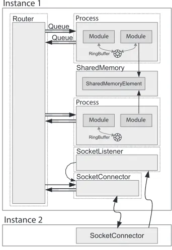
As depicted in Figure 4.1a, RoboFrame is a framework that allows the programmer to create a modular application, which is platform independent. The RoboApp library can be used for the actual robot application, which is build from modules (depicted in Figure 4.1a as blocks with 3 dots). RoboGUI is a QT (2008) graphical interface library, to create a user interface that can look into the process status. RoboFrame offers logging and configuration functionality.
Application
(a) Abstraction layers. The blocks with 3 dots are custom modules.
Instance 1
Process
Instance 2
Process
Module Module
Module Module
(b) Example of implementation
FIGURE4.1 - Structure of RoboFrame
Figure 4.1b shows an example of implementation. The object which is called aprocess, is a thread. A process can consists of multiple modules, which can use global data objects to com-municate among each other within one instance or through a router even among modules in different instances. Modules are C++ classes where its functions can be triggered by the sched-uler or a change in its connected data objects.
Sharing data among several modules can be done in two ways. One way is to store data in shared memory, the so calledBlackboard. In that case the data object needs to be locked for writing and reading. Data on the blackboard can be accessed by multiple readers and writers. The second way is aData Buffer, which is a one-to-one data exchange and is based on the ring-buffer principle. The ring-ring-buffer has a predefined number of elements and can handle besides standard data types also custom data types (which within RoboFrame are called Representa-tions).
Software framework analysis 11
a socket connection. In this way it is possible to create user interface application (e.g.: with RoboGUI) which can read and even adjust data within the robot application.
Furthermore it provides services for: • data logging
• configuration file interpreter
• finite state machine engine (with use of XABSL (2008))
4.2 Software framework choice for TUlip
To use RoboFrame for all the software function blocks, it also needs to provide real-time sup-port for the time critical parts. RoboFrame initially does not supsup-port real-time. However it has a well defined OS abstraction layer, which makes it possible to port it to a real-time OS. It is ex-pected that this porting cost a lot of time to implement and to evaluate. Another option, which is less time consuming, is to implement a self-written real-time module for the time critical parts. These are the sequence control, joint control and safety layers as described in Section 3.3. RoboFrame can be used only for the supervisory priority layer. This separation is depicted in Figure 4.2. Because of the limited time resources, this option have been chosen to be imple-mented.
FIGURE4.2 - Use of software frameworks in TUlip
4.3 Real-time operating system
(2008), known before as RTAI Fusion, has a progressive development and a large developers community. Xenomai has several skins to be compatible with other popular real-time OS’s. Is has been chosen to use Linux/Xenomai, because a lot of support is available and is easy to implement. However, Xenomai can only be used when the timing performance are satisfying the requirements. In order to evaluate the timing performance of Xenomai, a jitter test has been carried out, as explained in Appendix C. Jitter is the unwanted variation in periodical timing. It is the difference between the scheduled time and the actual execution time. For hard-real-time the worst-case jitter is important, however, no timing constraints are yet available for the function blocks which need hard-real-time. The timing constraints are determined by the digital controllers , which are expected to run at a frequency of 1k H z. Since the digital controllers are not designed yet and not timing constraints are available, it is chosen to use sufficient criterion: as reference, worst-case jitter should not exceed 1% of the periodic time . On the computer stack of TUlip, a periodical task is scheduled at 1k H z and the jitter is mea-sured while the system was fully loaded, as described in Appendix C. From the results of the test, Xenomai have been found to be suitable because the worst-case jitter stayed below 7µs, which is below 1%. With this result, it proven that Xenomai can achive the required real-time behavior and thus can be used.
4.4 Conclusions
In this chapter, RoboFrame and Orocos are analysed for usability in TUlip. From this analyses, it has been decided to use RoboFrame because of its modularity and lightweight characteristics. Since RoboFrame does not have real-time support, it has been chosen to implement a self-written real-time module for the time critical function blocks. In order to provide real-time support, a real-time OS is needed. After a short analysis, Xenomai is chosen to be used because of its good support and easy implementation. With a short test, it was proved that the jitter of a periodic task, running on Xenomai, is within acceptable bounds.
13
5 Analysis of joint controller organization
This chapter focuses on the analysis of configuring the joint controller by the basic behaviours. These two function blocks are part of the software architecture as discussed in Section 3.2. In Figure 5.1 the software architecture is represented with a more detailed view of the joint controller and basic behaviours blocks.
Robot status
World modeling
Decisions
Safety
Variable estimation
Communication
IO Joints
Basic behavior
Multiple control algorithms and topologies
FIGURE5.1 - How the controllers have to be organized
The basic behaviors block, consists of multiple basic behaviors. Each basic behaviour repre-sents a certain movement like walking or kicking. In order to perform these movements, the different joints have to be actuated. This actuation will be controlled by the joint controller function block. Each basic behavior configures and activates the necessary controllers to per-form the requested movement. How the controllers have to be organized to be fully adjustable by the basic behaviors, is the question which this chapter tries to answer.
5.1 Multiple controller configurations
In general most control problems are solved by designing a single-loop controller for an of-ten linearized plant. Such a single-loop controller has one mode: it contains one (optimized) algorithm to make a joint reach a certain setpoint (e.g. a desired torque, angular position or an-gular velocity). However, in a multi-joint, multi-mode system such as TUlip a lot of interaction among the joints exist and the required controller response can differ per situation.
single-input-single-output (SISO) controllers. In order to compensate for interaction among the joints a multi-input-multi-output (MIMO) controller can be used. In Figure 5.2(b) such a MIMO topology is depicted. It is possible to combine these two topologies as shown in Figure 5.2(c).
C1 J1
FIGURE5.2 - Examples of several common used controller topologies. T – motion trajectories;
C – control algorithm; J – joint actuations.
To be able to support multiple control algorithms and topologies, the controller organization should be as generic and flexible as possible. Besides these requirements, the requirement of light-weighted software has to be kept in mind for designing a suitable controller architecture. Furthermore, parameters and setpoints have to be set by the basic behaviors.
Three different options for organizing the controller algorithms are considered and evaluated on flexibility and generality:
• Configurable pool of controllers: The basic behavior can configure the joint control per joints to use certain algorithms and topology through an interface. As long as the system needs only SISO controllers, it is straight forward. The configuration would be: per joint a selection among several algorithms. However, as soon as combinations of MIMO and SISO controllers in different topologies are needed, the configuration becomes complex. It is highly generic, although it will be difficult to implement MIMO control topologies, this reduces the flexibil-ity.
• Selectable sets of controllers: The basic behavior can select among different predefined sets of algorithms and topologies per system. It reduces the complexity compared with the pre-vious alternative. However, in this case it is not possible to change the algorithm for a single joint with changing the controllers for all the joints.
• Controllers per basic behavior: Each basic behavior has its own customized control objects which implements a certain algorithms, in this way it can be totally on the demands of the basic behavior. The active basic behavior gives the pointer of its controller objects to the joint controller. The joint control can call a special function of the control objects in order to compute the controller algorithms per joint. This option is general and flexible, because the control objects can be totally customized per basic behavior.
It is chosen to design and implement a controller framework with use of control objects, be-cause it is a flexible and generic solution in order to organize controller algorithms, fully ad-justable by the basic behavior.
5.2 Principle of control objects
This section explains the basic principle and the use of the control objects. In Figure 5.3 the function blocks basic behavior and joint control are depicted in detail. The control objects are represented by the Joint 1, 2 ,3 blocks.
mul-Analysis of joint controller organization 15
Joint control
Basic behaviors
Joint controller
interface 3 2 Joint 1
FIGURE5.3 - Customized joint controllers per basic behavior, called: control objects.
tiple interfaces. The basic behavior adjust the custom joint controllers by setting parameters and setpoints. On the other side, the joint controller calls a function of the joint controller in-terface, which is associated with a custom control object, in order to compute the appropriate algorithm.
In Figure 5.4 a control object is depicted. The principle of a controller object is based on low level and high level controllers. As shown in Figure 5.2, controller configuration have certain topologies. These configuration can be split up in two levels, high and low. The distinction between low and high level is in general:
• Low levelcontains the control algorithm that is responsible for the dynamics of the joint and often realized as SISO PID controllers.
• High levelcontains the less time critical and CPU time consuming algorithms, such as setting parameters, generation of motion profiles and computation of a cascaded MIMO controller.
Low level High level
rapid states
Parameters
Calculate
Sequence control Loop control slow states
FIGURE5.4 - A control object
PID algorithm Configuration Setpoint, P, I and D values
Calculate Setpoint, P, I and D values
Calculate
FIGURE5.5 - Example joint control objects.qand ˙qare measured joint positions and velocities.
matrix will be computed by the high level part, requested by the basic behavior. As soon as the joint control request a computation of one of the joints, the low level part computes the output for all the joints depending on the mass matrix and returns the requested one. The remaining request of the other joints simply return the already computed values. Figure 5.5 (c) and (d) represents motion profile generators. Where in (c), the computation will be done by the high level and put in a list, so that the low level part can just fetch the next setpoint each time on a request of the joint control . In (d) the computation of the motion profile is done each time the joint control requests computation.
These object are just examples and can be implemented as needed.
5.3 Conclusions
In this chapter, the possible organizations of the joint controllers has been analysed and a concept for implementation the controllers is proposed, which complies to the stated require-ments. It is chosen that each basic behavior has its own set of control algorithms for the joints, in the so-called control objects. It is chosen because it is a flexible and generic solution in or-der to organize control algorithms so that they are fully adjustable by the basic behavior. The joint control reach the control objects through a generalized joint controller interface, in order to compute the control algorithms. The principle and use of the control object concept are explained by examples, which show that it is possible to implement different controller algo-rithms in a generic way.
17
6 Design and implementation of the joint controller
framework
The joint controller framework is the execution engine for the sequence control, loop control and safety layer, as discussed in Section 3.3. As described in Section 3.1, a requirement is that the loop controller and safety layer need to be executed hard-real-time. The sequence control layer has the requirement to be executed soft-real-time.
This chapter explains how the software is executed, and how the data is exchanged between the layers.
6.1 Time driven tasks with data storages
All the function blocks of the joint controller framework have to be implemented with use of a self-written real-time module, as discussed in Section 4.2.
Since controllers need to be executed periodically and the context of the basic behaviors (which is outside of the scope of this assignment) needs to be executed periodically, it is chosen to create periodical executed software components, which are calledtasks.
Each tasks has a priority. To achieve hard-real-time for tasks that implement function blocks that require hard-real-time, these tasks are given a higher priority than the tasks with function block that require soft-real-time.
In order to reduce complexity and overhead due to communication mechanisms, the goal is to create a minimum number of tasks. Therefore, all functions with the same timing require-ments are handled by the same task. Timing requirerequire-ments are the period time and priority. For instance, the data loop of: reading sensors, calculate the joint controllers and actuating the joints are all handled sequentially in one task grouped by joints with the same sampling rate. The function blocks within the different tasks, need to be able to configure each other and ex-change data. Since the tasks have different priorities and different period time, it is undesirable to couple the tasks for data communication. Therefore it has been chosen to use asynchronous communication. Communication is realized by shared memory in the so-calleddata storage. The concept of data storages is that only one task is responsible for one data storage. It is based on the concept that each function block in Figure 3.1 is responsible for one set of data, while multiple function block might use the data, as shown in Figure 3.1.
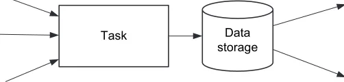
In Figure 6.1, ataskand adata storageare shown. The arrows indicate data transfer. Each data storage can only be written by one task. The task can update the storage by processing data from other data storages or external data. Each data storage can be read by a number of tasks.
Task Data
storage
FIGURE6.1 - A task responsible for a data storage
Figure 6.2 gives a representation of the tasks and data storages within the real-time software module. It consist of three tasks:
• Control engine
which correspond respectively to the control priority layers supervisory, sequence and loop control.
The tasksupervisory control interfacecommunicates with the supervisory software modules written with RoboFrame. It provides the robot status data for the supervisory software and receives commands to perform certain the basic behaviors. The implementation of this task is outside the scope of the assignment and will not be discussed any further.
Each basic behavior consists of a few motions. These motions are processed by a hierarchical state machine, where each state performs a motion. The state machine transitions and the state contents are periodical executed by the taskbasic behavior engine. The state contents configure and execute the high level of the control objects, as described in Section 5.2.
The low level algorithms of the control objects are executed by the taskcontrol engine. Further-more, the control engine performs the function block safety, the function block filtering and communication with IO of the robot hardware as well.
Realtime module
Joint states Control engine
Behavior engine Supervisory
control interface
Robot status
Joint config Behavior commands
Hardware
Robot joints Supervisory control
RoboFrame modules
FIGURE6.2 - Tasks and data storages within the real-time software module
6.2 Execution of the control objects
As mentioned by Visser et al. (2006) two different control approaches exists within digital con-trol. The so called ‘sample-compute-actuate’ and the ‘sample-actuate-compute’ in which the names refer to the order of the loop control processes.
Design and implementation of the joint controller framework 19
FIGURE6.3 - Timed-control implementation approaches (from Visser et al. (2006))
As suggested by Visser et al. (2006), the ‘sample-actuate-compute’ approach has been imple-mented.
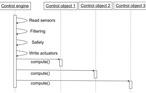
Figure 6.4 shows the sequence diagram of the control engine task. On each periodic trigger, the joint sensors are read first. The information is stored in theJoint statesdata storage. The data is filtered, in order to to estimate states (e.g.: joint velocities). This information is stored in the Joint states as well. The function safety checks if the current joint states are not out of their boundaries and that the actuation signal is appropriate. If it discovers that something is wrong (e.g.: joint exceeded a software end-stop, or a maximum velocity), it can perform a graceful degradation (Cooling, 2000) instead of failing the whole system. The actuation signal, checked by safety, is written to the actuators. These performed functions have practically a fixed execution time. Also, they can not be interrupted, since they are executed in a real-time tasks with the highest priority. In this way the jitter of actuation is tried to be minimized. The algorithms of the control objects are computed in the spare time of the execution period. It calls for each joint the joint controller interface, which refers to a customized controller object. The lower part of each control object can reach the joint states in the data storage which are updated in the beginning of this sequence.
Control engine Control object 1 Control object 2
Read sensors
Control object 3
Safety
Write actuators Filtering
compute()
compute()
compute()
FIGURE6.4 - The sequence of functions executed by the control engine
In Figure 6.5, the sequence diagram of the behavior engine task is shown. The behavior en-gine task updates the state machine according to the joint and robot states. The context of the current state is executed, which configures the control objects. The higher part of each con-trol object can reach the joint states and the robot states in order to perform it configuration algorithm.
6.3 Implementation
Behavior engine Control object 1 Control object 2
Updating state machine
Control object 3
configure()
configure()
configure()
FIGURE6.5 - The sequence of functions executed by the behavior engine
the basic behavior engine and the control engine.
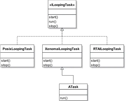
In order to create real-time tasks easily, an object-oriented abstraction layer for the Xenomai application programming interface has been created, as discussed in Appendix B. The commu-nication through data storages are realized by shared memory.
Implementation of two controller configurations have been realized, as discussed in Chapter 7. The classes used in the prototype are depicted in Figure 6.6. The prototype is focused on execution of the control objects and the functions safety and IO are not implemented yet. For both controller configurations, the basic behavior engine is composed of control objects. At a periodic trigger, it executes the high level algorithms (configuration) of the control objects. The control engine is composed of control object interfaces, which are associated with the actual control objects. On the periodical trigger of the control engine, it calls for every control object interface thecompute()function, in order to compute the low level algorithm of the associated control objects. The control objects can make use of the joint states in their algorithms.
«IControlObject»
virtual double compute()
CustomController
double compute()
CustomControlInterface
ControlEngine
JointStates BasicBehaviorEngine
n
1 n
FIGURE6.6 - Implemented classes of the joint controller framework prototype
6.4 Discussion on the extension of features
Since the implementation of the joint controller framework is in a experimental phase, two not yet fully implemented features will be discussed.
Non-blocking shared memory
Data exchange with use of the data storages is implemented as shared memory. Different tasks might perform a read or write request to the same data at the same time. Without a protection mechanism it might result in corrupted data.
Design and implementation of the joint controller framework 21
In a task with hard-real-time requirements, it is not desirable to wait for data that is locked by another task. When a higher priority tasks is blocked because a lower priority thread has locked the data, it is called priority inversion. Although blocking priority inversion can be solve by priority inheritance (the lower priority task inherits the priority of the highest priority task), it is highly undesirable because it decreases the predictability of the timing of the higher priority task. Especially, when
• the data is large
• locks are performed inefficiently • data is locked frequently
In these cases it is desirable to use non-blocking shared memory.
In Soetens (2006b) an principle for non-blocking shared memory is described and evaluated. A simple and clear picture is given in the presentation of Soetens (2006a). Basically it is having multiple copies of the data, in such a way that it is always possible for a writer to find ’free’ memory. As soon as a writer has updated the data, it marks the data as ‘most recent’. A reader always reads the most recent data.
The principle, as explained by Soetens (2006a), is for many-writer-many-reader setups. How-ever, the maximum number of readers and writers should be known in order to allocate enough memory, which grows linear with the number of readers and writers.
In case of hard-real-time threads sharing • a large data object
• frequent read data
it is worth to consider using non-blocking shared memory.
It can be useful, for instance, in a MIMO control object, where the high level computes the mass matrix and the low level need to access the mass matrix in order to calculate its algorithms. Since the computation of the mass matrix can be time consuming, with blocking shared mem-ory it should – calculate the mass matrix locale – lock data – copy – unlock data – in order to minimize the time of locking the data. While with non-blocking shared memory it can – calcu-late mass matrix to free buffer – mark buffer as most recent –. The second case does not have any extra overhead, while the benefit is that there is not chance on priority inversion.
Switching between loop controllers
Switching among control objects creates a potential undesired effect and in worst case insta-bility. In case of switching to a control object with an algorithm that uses memory, it could be initialized. For example switching to, for instance, a PID controller, which has one integrating action, it could be for initialize by the reverse calculation of the previous state, setpoint and actuation.
This is a hypothetical solution to a potential problem, it had not been proved nor tested. It only have been an trigger for implementing the possibility for initialization of controllers by the previous output before switching.
6.5 Conclusions
In this chapter, the design of the joint controller framework is discussed, which consists of real-time tasks in order to execute the function block with real-time requirement. In order to implement the data flow as in Figure 3.1, data storages have been implemented. Only one task is responsible for a data storage, while the others can read from it. The data storages have been implemented as shared memory in order to reduce overhead, compared to message based data exchange. Furthermore, the actuation of the hardware is done with the sample-actuate-compute approach in order to reduce jitter.
7 Realization of test setups and control configurations
In this chapter, the realization of two test setups is discussed. For the test setups two different control configurations have been used.
The test setups have been create in order to:
• test development iteration of the joint controller framework, • test the use of ‘controller objects’.
7.1 Implementation of the control objects
The use of control objects have been tested by implementing two controller configurations. 1 A controller configuration for the 12 joints of TUlip’s body, in order to stand up from prone
position. It was created by Daemen (2008) as a Master Thesis project. It consists of 12 SISO PID controllers with a sequence controller, which changes the setpoints and parameters of the PID controller according to the current state of the robot.
2 A controller configuration for a humanoid head, which is created by Visser (2008) as a Master Thesis project. The neck, head and eyes are connected to each other with 7 joints. The set-point to the controller is a set-point in a three-dimensional space (e.g. location of an interesting object). By inverse kinematics it steers the joints in order to focus the eyes to that point. These controller configuration were designed with use of 20-sim. Both controller configura-tions are split up in a high and low control loop, to fit in the concept of the control object (as designed in Section 5.2).
Setpoint and parameter generator state machine
Array of 14 PID controllers P, I, D and
q
q
ˆ
&
,
~
q
~
τ
q
(a) Body: Get up from prone position.
Inverse kinematics
Integrator
q
&
P
q
q
~
(b) Head: Follow target with the vision sys-tem.
FIGURE 7.1 - Two controller configurations implemented in control objects. Explanation of
the variables in the figures: P, I and D – controller parameters;q – desired joint position; ˜q – measured joint positions; ˙q – desired joint velocity; ˆ˙q – estimated joint velocity; τ– desired joint torque;P – 3D setpoint (target position). The variables in the erea between are stored in shared memory of the control object, it is the configuration of the low level algorithm.
posi-Realization of test setups and control configurations 23
tions ( ˜q). It generates parameters (P, I and D) and setpoint (q) for PID controllers in the lower level. The PID controllers compute the torques (τ) for actuation, according to the current joint positions ( ˜q) and velocities ( ˆ˙q).
The second controller configuration is implemented as shown in Figure 7.1b. A target position (e.g.: gathered by the vision system) is the setpoint for the higher level controller. The desired joint velocities for the joints ( ˙q) are computed by inverse kinematics and proportional control. The lower level is a simple integrator to obtain the desired joint positions (q).
Both controller objects have been implemented.
7.2 Testing the joint control framework with a model of the robot
Unfortunately, at moment of implementation of the controller objects, the robot was not op-erational yet. To bypass the missing robot, simulation models of the robot have been used in order to test the controller implementations.
Both the controller configurations mentioned in the previous section are developed and tested with use of models in 20-sim. These models are used in the test setup.
7.2.1 Computation of the robot model
In order to test the real-time framework, the model should be computed in real-time as well. This can be realized by Hardware-in-the-Loop (HIL), as described by Visser et al. (2004). A problem is that the computation of the given models on standard lab computers take longer than the simulated time. In case of the model of the body, a modern desktop computer com-puted 12ms for a model time of 1ms. In order to use these models for testing the real-time setup, a solution need to be found. Possibilities are:
1 Simplify the model and code 2 Use more computational power 3 Simulation of the framework
Both the models are designed with the 3D Mechanics Toolbox of 20-sim (2008). It has been cho-sen to not simplify the model, because it would require a revalidation of the model. However, the C-code generated by 20-sim could be optimized, which resulted in a computation time of 9ms, but it is still –of course– not real-time. For the second option, in order to compute the robot model real-time, a system should be used that is capable of compute ten time faster then a modern desktop computer. It is possible, for instance, to increase the computational power by using a cluster of computers. The third possibility is to do a step back, instead of testing the framework by HIL, to test the framework by simulation. Since the second option would require a lot of effort of setting up a HIL system, it has been chosen to test the framework by simulation. Simulation of the framework can be realized by modifying it in such a way, that it is possible to suspend the whole system. The feature of suspending the real-time tasks have been implemented and it is described in Appendix B.2. In Figure 7.2, the timing diagram of the basic behavior and control engine tasks is depicted. On the vertical dotted lines, the tasks get suspended in order to compute a time interval of the model, after it the system resumes again. In this way the real-time relation between the tasks is maintained. Compared with HIL, simu-lation of the framework has the advantage that no second computer is needed for computation of the model, because the computation of the model can be done at the stack as well.
7.3 Test setup
con-Basic behavior engine
Control engine
Time
FIGURE7.2 - Timing diagram of the basic behavior engine and control engine tasks. The dark
blocks represents the execution of the tasks, while the light gray blocks represents preemptions of a task.
nection to the second computer, depicted as the right box. On the second computer a instance of 20-sim is running. Through a customized DLL, the data can be requested and brought into the 20-sim simulation environment. Where the 3D visualization is the representation of the model states. In this way 20-sim can monitor the states of the model and is able to start and stop the joint controller framework.
FIGURE7.3 - Overview of the test setup
Both controller configurations have been tested with this setup, they will be further described in the next sections.
7.3.1 Joint controller framework with model-in-the-loop: Body
As shown in Figure 7.4, the joint controller framework exists of two asynchronous real-time tasks: Behavior engine and control engine. Which are periodical executed at 100H zand 1k H z
respectively. The behavior engine executes the higher level of the control object, which con-tains the setpoint and parameter generator, implemented as a state machine. The lower level of the control object is executed in the control engine. From the generated parameters (P, I and D) and setpoints, it computes the PID control algorithm. Instead of actuating the hard-ware, the controller ‘actuates’ the model, by computing 1msof simulation. While the model is computed, both real-time tasks are suspended. The joint positionsq from the model are the feedback signals for the PID controllers and motion controller. On request of the 20-sim application, the transformation matrices H of the limbs from the model and sends it over a network connection to the second computer, where the 3D visualization is the representation of the transformation matrices form the model.
7.3.2 Joint controller framework with model-in-the-loop: Head
Realization of test setups and control configurations 25
FIGURE7.4 - Joint controller framework with model-in-the-loop: Body
to focus the ‘eyes’ to the target. The control engine integrates the output of the inverse kine-matics by executing the lower level of the control object. The tasks are periodical executed at 10H z, 20H zand 1k H z respectively. Instead of sending the transformation matrices, only the joint positions are send to the visualization computer. The visualization computer computes locale the transformation matricesHin order to visualize the model.
Desktop computer
FIGURE7.5 - Joint controller framework with model-in-the-loop: Head
7.4 Results
have been made:
• Calculate the model at a higher frequency
• Tried different integrator algorithms for the model • Weakening the controller parameters
• Interpolating the signals from the controllers to the model
However, even with these changes it did not succeeded to control the model in a proper way. The head model is handled well by a fixed step integrator algorithm. The control configuration was set up with success. The ‘eyes’ of the head follow the with the joystick manipulated target. After the successful simulation of the framework with the head model, the framework is used to control the real head, as described in Visser (2008).
7.5 Conclusions
In order to test the joint control framework and the concept of controller objects, two controller configuration have been implemented. The controllers from 20-sim have been divided in a lower and higher controller part to fit in the concept of the control objects.
The concept of the higher and lower controller of the control object, allows to split up the con-troller in two parts. So that the hard-real-time control loop does not have to compute time consuming algorithms, which are able to run a lower sampling time. The concept of the con-trol objects serves a high flexibility of combining concon-trol algorithms as well. Two examples are the two implemented controller configurations.
A simulation setup with models of the robot have been realized to perform the test of the soft-ware, because the robot was not present yet. The setup might also be used later when the robot is operational to prevent the robot from damaging caused by buggy experimental code. The model of the body has not been successfully tested, because the C-code of the model did not work properly. However, the model of the head has been tested successfully in the frame-work simulation and the frameframe-work is used for the implementation of the head demo, as de-scribed in Visser (2008).
27
8 Conclusions and recommendations
8.1 Conclusions
A software architecture for TUlip is proposed. This modular software architecture consists of function blocks in which all required software functions are implemented. The function blocks have been mapped to a layered structure to divide them in real-time priority layers.
Several third-party robot software frameworks are analysed for usability in TUlip. From this analysis, it has been decided to use RoboFrame because of its modularity and lightweight char-acteristics. Since RoboFrame does not have real-time support, it has been chosen to implement a self-written real-time module for the time critical function blocks.
Xenomai is chosen to be used in order to provide real-time support, because of its good support and easy implementation. With a short test, it is proved that the jitter of a periodic task, running on Xenomai, is within acceptable bounds.
A controller architecture is proposed which complies to the stated requirements. It is chosen that each basic behavior has its own set of control algorithms for the joints, in the so called: Control objects. It is chosen because it is a flexible and generic solution in order to organize controller algorithms so that they are fully adjustable by the basic behavior. The concept of the higher and lower controller of the control object allows to split up the controller in two parts. So that the hard-real-time control loop does not have to compute time consuming algorithms, which are able to run a lower sampling time. In this way the load of the hard-real-time software part is minimized. The concept of the control objects serves a high flexibility of combining control algorithms as well.
A design has been made of the joint controller framework, which consists of real-time tasks in order to execute the function blocks with real-time requirements. A prototype of the joint controller framework has been made.
In order to test the prototype of the joint control framework and the concept of controller ob-jects, two controller configuration have been implemented in the simulated framework setup. The model of the body has not been successfully tested, because the generated C-code of the model did not work properly. However, the model of the head has been tested successfully in the framework simulation and the framework is used for the implementation of the head demo, as described in Visser (2008).
8.2 Recommendations
8.2.1 Porting RoboFrame to support real-time behavior
Instead of continuing with two separate frameworks, it might be useful to port RoboFrame to a real-time operating system, in order to create a light weighted framework that simplifies creating real-time applications. The well-defined OS abstraction layer of RoboFrame allows relatively easily porting.
8.2.2 Investigation performance of Orocos
consumption.
8.2.3 Switching between controllers while operational
For this assignment, a generic and flexible solution for organizing joint controllers has been proposed. However, it has not been tested what happen on switching between different con-troller configurations while the robot is operational. As mentioned in Section 6.4, a poten-tial problem is undesired effect or even instability when switching between controllers, which might be solved by initializing the controllers by inverse computation of the algorithm. Fur-thermore, switching between loop controllers can cause instability. The timing of switching from loop controller should be chosen carefully in order to omit instability.
8.2.4 Testing new controller implementations by simulating the framework
29
A Robot software framework to use for TUlip
In this chapter, several third-party robot software frameworks will be discussed.
A.1 Requirements for a robot software framework for TUlip
In the software architecture design, several layers are defined which implement different func-tionalities, as shown in Figure A.1 and explained in Section 3.3. The main requirement for a framework is the possibility to create such a modular and layered structure. The software that need to be created should be an executable that runs at the given computer stack and work with the given hardware. It is a challenge to implement all the functionalities discussed in Section 3.2 on the PC-104 stack, because of its limited resources. Therefore, the software framework (if used) should be light weighted. Among the modules, direct communication should be possi-ble. The loop control layer which is responsible for the joint controllers is time triggered and requires hard real-time behavior in order to guarantee low latency for actuation of the joints. Another issue is the licencing of the software. It should be free to use and adjustable.
Loop control & Safety Sequence control Supervisory control
Hardware
FIGUREA.1 - Software layers with responsibilities
The requirements that are used in order to make a selection from the available frameworks are summarized in the following list:
• Multi layered structure • Light weighted
• Inter-module communication • Real-time support
• Open
Furthermore additional requests were used to indicate the usability of the framework in global, these are:
• Scripting engine: To adjust software at runtime
• State machine engine: For executing state dependent software
• Library components: Already developed components that might be used • Library of basic functions: For example mathematical function