Power Loss minimization and voltage profile improvement
using Autonomous Group Particle Swarm Optimization in a
distributed power system
C.Koteswari, R.Indhu, A.Chandra Babu,
1
M.Tech, Department of EEE, YITS,Tirupati
2
Asst.Prof, Department of EEE, YITS,Tirupati
3
HOD, Department of EEE, YITS,Tirupati
ABSTRACT-Growing concerns over environmental impacts, conditions for improvement of the whole distribution network, and rebate programs offered by governments have contributed to an increment in the number of DG units in commercial and domestic electrical power output. It is known that the non-optimal size and non-non-optimal placement of DG units may lead to high power losses, bad voltage profiles. Therefore, this paper introduces a sensitivity analysis to determine the optimal sitting and sizing of DG units. A new methodology AGPSO is used to reduce the active power losses and also to improve the voltage profile. The effectiveness of the proposed method is demonstrated through IEEE 33 bus standard test systems. The simulation results show that AGPSO can obtainthemaximumpowerloss reductions.
Index Terms—Power Flow (CPF), Loss Sensitivity Analysis (LSA), Autonomous Groups Particles Swarm Optimization (AGPSO).
I. INTRODUCTION
DISTRIBUTED generation (DG) is going to play a majorrole in power systems worldwide. The importance of DGs in future smart grids increases considering thefact that DGs will have a role in system security, reliability, efficiency, and quality as well. Active management of distribution networks as a lower level system may act similar to a catalyzer, speeding up the formationof smart grids. As a key function in active management, DGsmust be able to face the contingency conditions, while playinga remedial role in the system security. But current standards andpractical experiences force DGsto be disconnected in the caseof contingency. Also, DG units “shall not actively regulate thevoltage at the point of common coupling”. Thispolicyishardto implement at this growth rate of DGs in the power
systems,as a disruption of a large amount of DGs for a small-scale contingency will result in a bigger one. DGs capability can be usedto clear voltage stability problems, as a cause of the most recent blackouts. Considering that most DGs are located at the distribution level, determination of the best locations for installing DGs to maximize their benefits is very important in system design and expansion. A DG placement problem is solved by using voltage stability techniques (i.e., continuous powerflow, while the objective is to maximize the voltage and simultaneously minimize the losses.
Particle Swarm Optimization (PSO) is one of the most widely used evolutionary algorithms inspired by the social behavior of animals. The simplicity and inexpensive computational cost make this algorithm very popular. Due to these advantages, PSO has been applied to many domains such as medical detection, grid scheduling, robot path planning, video abstraction, optical buffer design, and Neural Networks. In spite of these advantages, trapping in local minima and slow convergence rate are two unavoidable problems. These two problems deteriorate with increased problem dimensionality.
other words, the particles are obliged to search without any self-determination and intelligence.
In this paper, we propose a new approach of utilizing autonomous groups to give particles a sort of independence with the purpose of increasing performance. Autonomous Group of PSO has more advantages than PSO algorithm. By using AGPSO algorithm the losses are reduced more and voltage is maximized.
II VOLTAGE-STABILITY PROBLEM IN DISTRIBUTION NETWORKS
A.Problem Identification
Voltage collapse usually occurs in heavily loaded systems that do not have sufficient local reactive power sources and consequently cannot provide secure voltage profile for the system .This reactive power shortage may lead to wide-area blackouts and voltage-stability problems as has occurred in many countries. The shortage can be alleviated by an increasedshare of DGs in low-voltage (LV) distribution systems to improve low-voltage stability. These days, most DG technologies, such as synchronous machines, power-electronic interfacedevices (e.g., photovoltaic cellsand micro turbines), and even new induction generators [e.g., doubly fed induction generators (DFIGs)], are capable of providing a fast, dynamic reactivepower response. This capability can be used by the system operators to enhance system security and stability. Since a generatorlocation affects the system voltage stability, it is important toidentify the most effective buses to install a DG.
B.Continuous Power-Flow Methodology
The determination of maximum loading is one of the mostimportant problems in voltage-stability analysis that cannot becalculated directly by modal analysis. Considering a loadingscenario, a continuous powerflow uses a successive solutionto compute the voltage profile up to a collapse point (i.e., where the Jacobian matrix in becomes singular, to determine thevoltage security margin (VSM). The VSM is knownas the distance from an operating point to a voltage collapsepoint. In the successive
procedure, the power at the loadsincreases continuously by a scaling factor𝛿
as
𝑃𝐿= 𝛿𝑃𝐿𝑂(1)
𝑄𝐿= 𝛿𝑄𝐿𝑂 (2)
Where 𝑃𝐿𝑂and 𝑄𝐿𝑂are the base-case load
active and reactive powers. The generated power at each generator can be freely scaled by a scaling factor or may be limited by its boundary conditions.
III POWERFLOW SOLUTION
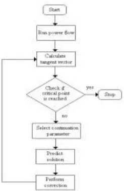
The Jacobian matrix of power flow equations becomes singular at the voltage stability limit. Continuous power flow overcomes this problem. Continuous power flow finds successive load flow solutions according to a load scenario. It mainly consists of two steps.
They are:1.prediction step 2. Correction step
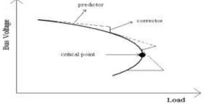
From a known base solution, a tangent predictor is used so as to estimate next solution for a specified pattern of load increase. The corrector step then determines the exact solution using Newton-Raphson technique employed by a conventional power flow. After that a new prediction is made for a specified increase in load based upon the new tangent vector. Then corrector step is applied. This process goes until critical point is reached. The critical point is the point where the tangent vector is zero. The illustration of predictor-corrector scheme is depicted in Figure 1.
Selection of continuation parameter is important in continuous power flow. Continuation parameter is the state variable with the greatest rate of change. Initially, is selected as continuation parameter since at first steps there are small changes in bus voltages and angles due to light load. When the load increases after a few steps the solution approaches the critical point and the rate of change of bus voltages and angles increase. Therefore, selection of continuation parameter is checked after each corrector step. The variable with the largest change is chosen as continuation parameter. If the parameter is increasing +1 is used, if it is decreasing -1 is used.
Fig 2: Flow chart for continuous power flow
The continuous power flow is stopped when critical point is reached as it is seen in the flow chart. Critical point is the point where the loading has maximum value. After this point it starts to decrease. The tangent component of λ is zero at the critical point and negative beyond this point. Therefore, the sign of dλ shows whether the critical point is reached or not.
IV SENSITIVITY ANALYSIS FOR OPTIMAL DG PLACEMENT
Sensitivity analysis is used to compute the sensitivity factors of candidate bus locations to install DG units in the test systems. Let us consider a line
section consisting an impedance of Ri+jXi, and a load of PL, eff+QL, eff connected between i−1 and i buses as given below.
Active power loss in the ith branch between the lines i-1 and I is given by
𝑃
𝑙𝑖𝑛𝑒𝑙𝑜𝑠𝑠= 𝑅
𝑖∙
(𝑃
𝐿𝑖,𝑒𝑓𝑓2
+ 𝑄
𝐿𝑖,𝑒𝑓𝑓2
)
𝑉
𝑖2(3)
Thus the Loss sensitivity factor is given as:
𝐿𝑆𝐹 =
𝜕𝑃
𝑙𝑖𝑛𝑒𝑙𝑜𝑠𝑠𝜕𝑃
𝐿𝑖,𝑒𝑓𝑓=
2 ∗ 𝑃
𝐿𝑖,𝑒𝑓𝑓∗ 𝑅
𝑖𝑉
𝑖2(4)
Thus from the above equation Loss Sensitivity Factors can be calculated and arranged in the descending order for finding the optimal locations to place DG units.
V OVERVIEW OF THE PSO ALGORITHM
PSO is an evolutionary computation technique that was proposed by Kennedy and Eberhart. It was inspired from the social behavior of bird flocking which uses a number of individuals (particles) flying around the search space to find the best solution. The particles trace the best location (best solution) in their paths over the course of iterations. In other words, particles are influenced by their own best locations found as well as the best solution obtained by the swarm These concepts have been mathematically modeled using a position vector (x) and velocity vector (v) of length D, where D indicates the dimension (number of variables) of the problem. In the course of iterations, a particle adjusts its position and velocity as follows
𝑉𝑖𝑡+1= 𝑊𝑉𝑖𝑡+ 𝐶1× 𝑟𝑎𝑛𝑑 × (𝑝𝑏𝑒𝑠𝑡𝑖− 𝑥𝑖𝑡) + 𝐶2 × 𝑟𝑎𝑛𝑑 × (𝑔𝑏𝑒𝑠𝑡 − 𝑥𝑖𝑡) (5)
where w is the inertial weight which is responsible for controlling the PSO algorithm’s stability and usually is in [0.4, 0.9], c1 is the cognitive coefficient that controls the influence of the individual memory of good solutions found, conventionally selected in (0, 2], c2 is the social factor also conventionally chosen from the range (0, 2] which controls the extent to which a particle’s motion is influenced by the best solution found by the whole swarm, rand is a random number between 0 and 1 which tries to give PSO more randomized search ability, and pbest and gbest are two variables to store the best solutions obtained so far by each particle and the whole swarm respectively. As can be observed, there are three main coefficients, w, c1, andc2. Dynamic tuning of these parameters is a way to give particles different behaviors as the algorithm proceeds. In this work c1 and c2 are targeted to increase the performance of PSO.
VI MOTIVATION OF PROPOSED METHOD
Finding the global minimum is a common, challenging task among all minimization methods. In population-based optimization methods, generally the desirable way to converge towards the global minimum can be divided into two basic phases. In the early stages of the optimization, the individuals should be encouraged to scatter throughout the entire search space. In other words, they should try to explore the whole search space instead of clustering around local minima. In the latter stages, the individuals have to exploit information gathered to converge on the global minimum. In PSO, with fine-adjusting of the parameters c1 and c2, we can balance these two phases in order to find global minimum with fast convergence speed. Considering these points, we propose the autonomous groups concept as a modification of the conventional PSO. In this method, each group of particles autonomously tries to search the problem space with its own strategy, based on tuning c1 and c2. The groups strategies can contain constant, linear time-varying, exponential, or logarithmic time-varying values for c1 and c2.
AUTONOMOUS GROUPS AND AGPSO ALGORITHM
The concept of autonomous groups is inspired by the individuals’ diversity in animals
flocking or insects swarming. In any gathering, individuals are not quite similar in terms of intelligence and ability, but they all do their duties as a member of the group. Each individual’s ability can be useful in a particular situation.
In a termite colony, for instance, there are four types of termites such as soldier, worker, babysitter, and queen. They all have diverse abilities, but these differences are necessary for survival of their colony. Soldiers have greater bulk with giant jaws in order to fight with enemies. Workers are smaller than soldiers, so they can move around very fast to find and provide food for the colony. They also have the ability of excavating to build the nest. The queen and babysitters reproduce and raise children. These four types of termite can be considered as four autonomous groups which have a common goal of promoting the colony’s survival.
In conventional PSO, all particles behave the same in terms of local and global search, so particles can be considered as a group with one strategy. However, using diverse autonomous groups with a common goal in any population-based optimization algorithm theoretically could result in more randomized and directed search simultaneously.
Fig3.Pseudo-code for the proposed modification of PSO algorithm (AGPSO)
To see how autonomous groups are effective in AGPSO some points may be noted:
•Autonomous groups have different strategies to update c1, so particles could explore the search space locally with different capability than the convectional PSO.
•Autonomous groups have different strategies to update c2, so particles could follow social behavior more autonomously than the conventional PSO.
VII SIMULATION RESULTS
In this paper, a new modification of PSO called AGPSO is proposed utilizing the concept of autonomous groups inspired by the diversity of individuals in natural colonies.. The results show that AGPSO has merit compared to other algorithms in terms of convergence speed, particularly for problems of higher dimensionality. The results also showed that dividing particles in groups and allowing them to have different individual and social behavior can improve the performance of PSO significantly without any extra computational burden.
For future studies, it would be interesting to apply AGPSO in optimization problems to evaluate the efficiencies of AGPSO in solving real world problems. Increasing the number of autonomous groups is also worthy of investigation. Moreover, employing different types of function with greater variety of slopes, curvatures, and interception points is recommended for future study
Fig4: Voltage profile for different placement scenarios
Fig5: Active power losses vs Number of buses
Fig6: Reactive Power Losses vs Number of buses
0 5 10 15 20 25 30 35
0.91 0.92 0.93 0.94 0.95 0.96 0.97 0.98 0.99 1
Voltage Profile Vs Buses
Buses
V
o
lt
a
g
e
P
ro
fi
le
i
n
p
.u
Base case DG33 DG33&18 DG3318&32
Basecase 1DG 2DG 3DG
0 0.5 1 1.5 2 2.5
Active Power Losses
Cases
L
o
s
e
s
s
i
n
(
P
.u
)
Basecase 1DG 2DG 3DG
0 0.2 0.4 0.6 0.8 1 1.2 1.4
Reactive Power Losses
Cases
L
o
s
e
s
s
i
n
(
P
.u
Fig7:Voltage profile for different placement scenarios with AGPSO
Fig8:Active power losses vs Number of buses With AGPSO
Fig9:Reactive Power Losses vs Number of buses
8. CONCLUSION
In this thesis, an
Autonomous Group
Particle Swarm
algorithm for DG placement in
radial distribution networks is presented. Modal
analysis and CPF are used for determining DG
placement
candidates, while
the
loading
parameter is the comparison index for selecting
the best DG places. The places are ranked using
an MERC method, which determines a priority
list of DG locations for reactive power
compensation during occasions of reactive
power shortage. The placement algorithm is
executed on the well-known 33 bus radial
distribution network, and the results show the
remedial effect of DGs, both in loss reduction
and voltage profile improvement in normal
operation, and enhancement of the loading
parameter in the case of voltage instability. The
ranking method is executed over the obtained
candidates to provide a priority list from the
viewpoint of reactive power compensation in the
case of shortage. The main objective is to serve
a high amount of load as possible with a higher
voltage when a shortage occurs, while the
placement algorithm seeks the maximum VSM
in the presence of a voltage stability problem.
The results show that the best candidate for DG
placement is different from the best location for
reactive power compensation. So the long term
DG placement problem can be solved by the
proposed AGPSO algorithm.
9. REFERENCES
[1]M.E.BaranandF.F.Wu,“Networkreconfigurati
on in distribution systems for loss reduction and
load balancing,”IEEE Trans. PowerDel., vol. 4,
no. 2, pp. 1401–1407, Apr. 1989.
0 5 10 15 20 25 30 35
0.91 0.92 0.93 0.94 0.95 0.96 0.97 0.98 0.99 1 1.01
Voltage Profile Vs Buses
Buses
V
o
lt
a
g
e
P
ro
fi
le
i
n
p
.u
Basecase 1DG 2DG 3DG AGPSO 3DGs
Basecase 1DG 2DG 3DG AGPSO 3DGs
0 0.5 1 1.5 2 2.5
Active Power Losses
Cases
L
o
s
e
s
s
i
n
(
P
.u
)
Basecase 1DG 2DG 3DG AGPSO 3DGs
0 0.2 0.4 0.6 0.8 1 1.2 1.4
Reactive Power Losses
Cases
L
o
s
e
s
s
i
n
(
P
.u