A Coding Metasurface with Properties of Absorption and Diffusion
for RCS Reduction
Tong Han, Xiang-Yu Cao*, Jun Gao, Yan-Long Zhao, and Yi Zhao
Abstract—A low-radar cross section (RCS) coding metasurface (MS) with properties of absorption and diffusion for both normal and oblique incidences is proposed in this paper. The coding MS is composed of a miniaturized perfect metamaterial absorber (PMA) and a wideband artificial magnetic conductor (AMC) in a shared aperture. In addition, to avoid strong scattering energy appearing at specific directions, genetic algorithm (GA) is adopted to search the optimal layout of the two MS elements. Simulated and experimental results confirm the properties of coding MS and indicate that the 6-dB RCS reduction bands under TE- and TM-polarized normal incident waves are 6.28 GHz–9.16 GHz and 6.33 GHz–9.41 GHz, respectively.
1. INTRODUCTION
Recently, metasurface (MS) constructed by sub-wavelength metamaterial structures [1] has been studied in depth due to its favorable characteristics in manipulating electromagnetic waves, such as electromagnetic invisibility for antennas [2, 3], polarization conversion [4, 5], perfect absorption [6–8], and anomalous reflection [9], among which the MS with low-radar cross section (RCS) [10–12] is of crucial significance in military practice.
Generally, there are mainly two methods adopted to reduce RCS by MS: absorption and phase cancellation. For the first method, the handiest instrument is called perfect metamaterial absorber (PMA) [6], which has the advantage of extremely low profile. However, PMA usually has narrow-band absorption, and the half power narrow-bandwidth (HPBW) is less than 5%. For the second method, it is significant to produce an effective phase difference in a certain band. In 2007, Panquay et al. first proposed a chessboard-like MS composed of AMC and perfect electronic conductor (PEC) whose RCS reduction can be achieved based on the principle of phase cancellation [13]. To expand the RCS reduction bandwidth, two AMC cells with distinct structures were combined to form a MS in a chessboard configuration, and the 10 dB RCS reduction bandwidth was expanded to 40% [14] In 2014, Cui et al. proposed the concept of coding metamaterials [15], and arbitrarily desired scattering patterns could be obtained by means of different coding sequences. Based on this idea, a series of works using coding MS were reported for RCS reduction [16–18]. Moreover, to achieve accurate bandwidth control of low-scattering MS, a new-type coding MS composed of three basic AMC elements was presented by Zhao et al. in 2016 [19]. In summary, RCS reduction of the MS is usually achieved by using the two methods independently with either PMA or AMC. Recently, Li et al. [20] designed a MS made up of PMA and AMC in a way of shared aperture. This idea provides a novel path to reduce RCS in multiple approaches. However, the large structure of PMA and narrow in-phase bandwidth (−90◦ <reflection phase<+90◦) [21] of AMC with conventional square patch restrict the miniaturization and wideband RCS reduction performances of the MS to some extent. In addition,
Received 12 April 2017, Accepted 24 June 2017, Scheduled 14 July 2017 * Corresponding author: Xiang-Yu Cao ([email protected]).
four strong redirected scattering beams distributed along the diagonal lines are induced due to the chessboard layout, which is infaust for the electromagnetic stealth.
Inspired by the research situation, in this paper, unit cells of miniaturized PMA and wideband AMC are designed using the technology of fractal firstly. Secondly, based on the concept “coding metamaterials” genetic algorithm (GA) is adopted to search the optimal layout constituted by PMA and AMC, whose scattering energy is confined in a lower degree in all directions. Lastly, the simulation results manifest that the coding MS possesses the properties of absorption and diffusion, and the experimental results indicate that the 6-dB RCS reduction bands for normal TE and TM waves are 6.28 GHz–9.16 GHz and 6.33 GHz–9.41 GHz, respectively.
2. DESIGN AND ANALYSIS OF MS UNIT CELLS
In [22], the relationship among fractal dimension d, ordern and the fundamental mode frequencyf of multi-resonant dipole antennas using fractal curves can be expressed as:
f =f0·
1−e(n−1)/n·(lnd/d)
(1)
wheref0 represents the fundamental mode frequency of common dipole antennas with the same size as
the proposed antennas. Although the formula is used to analyze antennas with the given structures, it can be inferred that the larger value ofnis, the better performance of miniaturization can be achieved when d is a constant. Hence, as shown in Fig. 1, a fractal PMA with a three-order trapezoid slot
h l
(a) (b) (c)
Figure 1. Schematics of PMA under different orders. (a) One-order PMA; (b) Two-order PMA; (c) Three-order PMA.
6 7 8 9 10 11
0.0 0.2 0.4 0.6 0.8 1.0
Ab
sorp
ti
vi
ty
Freq [GHz]
one-order two-order three-order
structure is designed based on the common PMA with a one-order cross-shaped slot structure, in which the optimized parameters are: p= 5 mm,l= 4.8 mm,l1 = 4 mm,l2= 1.5 mm,l3 = 3 mm,l4 = 0.7 mm,
h= 0.5 mm. Comparing the proposed PMA with the original one, it can be found from Fig. 2 that the absorptivity is increased from 74.5% to 99.6% and the resonant frequency reduced from 9.44 GHz to 6.6 GHz. It is apparent that miniaturization of the proposed PMA is enhanced by 43% compared with the original one.
The proposed wideband AMC is shown in Fig. 3, in which the grey portions surrounded by black dash lines are cut from the original AMC (p2 = 0 mm) with the square patch, and the parameters
are: p = 5 mm, p1 = 4.8 mm, H = 3 mm (p2 remains optimized). From Fig. 4, it is apparent that
in-phase bandwidth of the AMC becomes wider asp2 increases. At the same time, each AMC performs
total reflection for the incident wave when p2 varies. To determine the value of p2, the reflectivity of
PMA and phase differences between PMA and AMC with differentp2 are calculated by HFSS 14.0, as
shown in Fig. 5. It can be inferred that the first reduction peak will appear at 6.6 GHz due to perfect absorption of PMA for the incident waves. In addition, the second reduction peaks will appear at 7.25 GHz, 8.1 GHz and 9.35 GHz due to the most sufficient phase cancellation between PMA and AMC withp2 = 1.1 mm, 1.5 mm and 1.9 mm, respectively. In particular, our goal is to achieve RCS reduction
by MS in a consecutive broadband, which means that frequency of the second reduction peak should not
H F4B
Figure 3. Geometry of the proposed AMC.
5 6 7 8 9 10 11 12
-135 -90 -45 0 45 90 135 180 R efle ct io n A m p lit u d e R efl ec ti o n P h as e [de g] Freq [GHz]
p2=0 mm p2=1.1 mm p2=1.5 mm p2=1.9 mm
0.90 0.92 0.94 0.96 0.98 1.00
Figure 4. Reflection characteristics of AMC with differentp2.
6 7 8 9 10 11 12
0.0 0.2 0.4 0.6 0.8 1.0 R eflectivity Freq [GHz] PMA
p2=0 mm AMC
p2=1.1 mm AMC
p2=1.5 mm AMC
p2=1.9 mm AMC
60 120 180 240 300 Phas e D if fe re nce[ deg]
be too close to or too far from the first one. As a result, we choose the AMC withp2= 1.5 mm as the
optimal one, for which the consistency of band and broadband characteristics can be better achieved than the other two. In summary, there will be two reduction peaks for the MS at the frequencies of 6.6 GHz and 8.1 GHz, for which the RCS reduction bandwidth will be broadened in a way of cascade connection.
3. ARRAY DESIGN AND SIMULATION ANALYSIS
It is known that out of the absorptive band, PMA exhibits total reflection for the incident wave with a π phase response. Based on this condition, we study the array design to achieve diffusion effect. A block contains 5×5 MS unit cells is generated to satisfy the period boundary condition of the unit cell, and next a MS array that contains 6×6 blocks is adopted to illustrate the array design after considering the time cost of the optimization and computation complexity in the full wave simulation. Then, the total scattering field of the array can be regarded as the superposition of the scattering field from each basic block [23], which can be described as:
SFM×N =
M
m=1
N
n=1
sfmn=EP ·SAFM×N (2)
whereM =N = 6 EP represents the pattern function of each block, which is supposed to be changeless in the design. SAFM×N(θφ) represents the array factor which can be expressed as follows,
SAFM×N =
M
m=1
N
n=1
(ej(2λπdx·(m−M2+1)sinθcosφ+2λπdy·(n−N+12 )sinθsinφ)·ejψmn) (3)
wheredxanddyrepresent the distance between two adjacent blocks along thex- andy-axes, respectively. ψmn is the reflection phase of any block in the array. θ and φ are the polar and azimuthal angles, respectively. Based on the concept of coding metamaterials, we can nominate the block of PMA as “0” element with a 180-deg reflection phase and nominate the block of AMC as “1” element with a 0-deg reflection phase. Then, layout of the array can be expressed by a 6×6 coding matrix with 0–1 elements. As a result, constitution of the matrix becomes the crux which influences the scattering performance of the array. For example, Li et al. [20] employed a chessboard-like matrix to achieve RCS reduction at the normal direction, but this would lead to four strong redirected scattering beams at the backward space. In order to solve the problem caused by the regular matrix, we adopt genetic algorithm (GA) to search the optimal layout of the matrix. GA is an intelligent method solving the problem of global search, which does not start to search the optimal layout from the single solution but a string of solution assembles. In other words, GA is better at escaping from the local optimal solution than the conventional algorithms and also possesses the advantages of strong robustness and rapid convergence. The main parameters of GA are the population size sp, number of iterations N, crossover probability
pc and mutation probability pm. In this design, the parameters of sp, N, pc and pm are set at 200, 500, 0.8 and 0.05, respectively. In particular, our objective is to search the best coding matrix (Mbest) leading to a scattering pattern with the smallest peak value. Thus, the peak value ofSAF6×6 is utilized
as the fitness function:
fitness = max(SAF6×6) (4)
A flowchart of GA for optimizing the coding matrix is summarized in Fig. 6. Fig. 7 gives an evolution plot of max (SAF6×6). From Fig. 7, the curve descends sharply at the beginning, and then it
tends to be constant when the number of iterations is larger than 50, which verifies the rapid convergence of GA.
The calculated 3-D patterns for max (SAF6×6) of the chessboard-like matrix and optimal matrix
are shown in Fig. 8. It can be seen that the scattering energy fluxes of the optimal matrix are distributed more uniformly at the backward space than the chessboard-like matrix, indicating that the diffusion property of the MS is achieved after the layout optimization.
1 over
Figure 6. Flowchart of GA for optimal coding matrix.
0 100 200 300 400 500
6.4 6.6 6.8 7 7.2 7.4 7.6 7.8
Number of iterations
m
ax
(SA
F(
6
×
6
))
Figure 7. The evolution plot of max (SAF6×6).
(a) (b)
Figure 8. 3-D scattering patterns for different coding matrixes. (a) chessboard-like matrix; (b) optimal matrix.
PMA H(y)
E(x) k(z)
Figure 9. Geometry of the proposed coding MS.
decrease obviously as the incidence angle increases, while the regularity is inapplicable to the TE waves. This is attributed to the asymmetric structure of coding MS.
6 7 8 9 10 11 12 0
3 6 9 12 15 18 21 24
RCS Reductio
n[dB]
Freq [GHz]
TE 0 deg TE 15 deg TE 30 deg TE 45 deg
6 7 8 9 10 11 12
0 3 6 9 12 15 18 21
RCS Re
du
ct
io
n
[dB]
Freq [GHz]
TM 0 deg TM 15 deg TM 30 deg TM 45 deg
(a) (b)
Figure 10. RCS reduction curves under TE- and TM-polarizations with different incident angles. (a) TE polarization; (b) TM polarization.
6 7 8 9 10 11 12
0 45 90 135 180 225 270
P
h
ase D
if
fer
ence[
de
g]
Freq [GHz]
0 deg 15 deg 30 deg 45 deg
Figure 11. Phase differences between PMA and AMC under various incident angles.
0.005
(a) (b)
20
RCS (dBsm)
(a) (b)
Figure 13. Scattering spectra in the backward space at 8.1 GHz. (a) PEC; (b) coding MS.
60
RCS (dBsm)
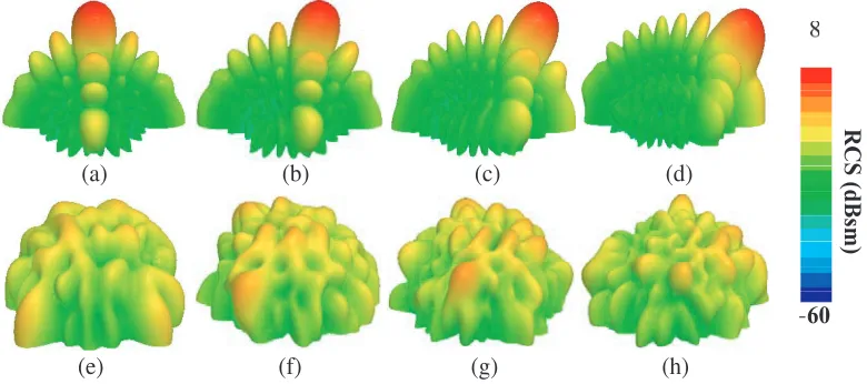
(a) (b) (c) (d)
(e) (f) (g) (h)
Figure 14. 3-D scattering patterns under different incident angles. (a) PEC at 8.1 GHz, 0 deg; (b) PEC at 8.5 GHz, 15 deg; (c) PEC at 9.1 GHz, 30 deg; (d) PEC at 9.9 GHz, 45 deg; (e) coding MS at 8.1 GHz, 0 deg; (f) coding MS at 8.5 GHz, 15 deg; (g) coding MS at 9.1 GHz, 30 deg; (h) coding MS at 9.9 GHz, 45 deg.
space at 8.1 GHz are shown in Fig. 13, in which the results of PEC are illustrated in the same color map as comparison. From Fig. 13, the scattering energy fluxes are distributed mainly along the normal direction while the fluxes of coding MS are suppressed in a wide angle range, proving the scattering diffusion property of the proposed MS.
In order to comprehend the diffusion effect more vividly, Fig. 14 provides the 3-D scattering patterns of both PEC and coding MS illuminated by TE-polarized waves with incident angles of 0◦, 15◦, 30◦ and 45◦ at the corresponding frequencies where the second reduction peaks appear in Fig. 10(a). It can be clearly seen that the layout of coding MS leads to a better uniform reflection for the incident waves, and value of the scattered energy is confined within a low degree.
4. FABRICATION AND MEASUREMENT
To demonstrate the validity of simulated results, a sample of coding MS fabricated with the technology of optical lithographic is tested in an anechoic chamber, as depicted in Fig. 15. The reflectivityS21of coding
Horn antennas
Foam platform Sample
Figure 15. The fabricated coding MS and experiment setup.
6 7 8 9 10 11 12
0 5 10 15 20 25 30
RCS Reduction[dB]
Freq[GHz]
Measured TE 0deg Simulated TE 0deg Measured TE15deg Simulated TE 15deg Measured TE 30deg Simulated TE 30deg Measured TE 45deg Simulated TE 45deg
6 7 8 9 10 11 12
0 5 10 15 20 25
RCS Reduction[dB]
Freq[GHz]
Measured TM 0deg Simulated TM 0deg
Measured TM 15deg Simulated TM 15deg
Measured TM 30deg Simulated TM30deg
Measured TM 45deg Simulated TM 45deg
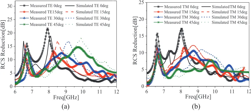
(a)
(b)
Figure 16. Simulated and measured RCS reduction curves under various incident angles. (a) TE polarization; (b) TM polarization.
is reduced from 6 GHz–12 GHz for both TE and TM waves with various incident angles. Additionally, the 6-dB RCS reduction bands for TE- and TM-polarized normal incidences are 6.28 GHz–9.16 GHz (37.3% relative bandwidth) and 6.33 GHz–9.41 GHz (39.1% relative bandwidth), respectively. The maximum RCS reduction is obviously decreased under the condition of TM polarization as the angles of incidence increase, which is coincident with the simulation in Fig. 10(b). Furthermore, compared with the simulated results, the measured second reduction peaks are shifted to lower frequencies at the range of 0.5 GHz, which can be attributed to fabrication errors, ambient noise and imprecise angles between the sample and horn antennas. In summary, reasonable agreement between the measurements and simulations verifies the low scattering of the MS in broadband and broad-angle.
Table 1. Comparisons between the proposed coding MS and the reference MS in Ref. [20].
Proposed coding MS Reference MS in Ref. [20]
Dimensions of PMA 0.11λ0 0.17λ0
In-phase bandwidth of AMC 6.35 GHz–10.25 GHz (47%) 6.15 GHz–8.1 GHz (27.4% )
Layout optimization? Yes No
Scattering effects at
the non-absorptive band Diffusion
Four redirected scattering beams 6-dB RCS reduction bandwidth
for normal TE waves 6.28 GHz–9.16 GHz (37.3%)
5.5 GHz–5.8 GHz (5.3%), 6.54 GHz–7.6 GHz (15%) Remarks: λ0 is the wavelength of incident wave at the corresponding resonant frequency
5. CONCLUSION
In this paper, a coding MS with properties of absorption and diffusion for RCS reduction in broadband and wide-angle has been designed, simulated, fabricated and measured. The elements of miniaturized PMA and wideband AMC are employed to construct the MS firstly, and then GA is utilized to optimize the layout of the MS to avoid strong redirected scattering patterns caused by the regular layout. The simulation results verify the absorption and diffusion properties of the MS. Scattering performances of the MS under TE and TM polarizations with various incident angles have also been investigated and tested in an anechoic chamber. The measured results indicate that the MS can achieve RCS reduction in broadband and wide angle.
ACKNOWLEDGMENT
This work is supported by the National Natural Science Foundation of China (No. 61471389, No. 61501494, and No. 61671464) and the Doctoral Foundation of Air Force Engineering University (No. KGD08091601). Authors also thank the reviewers for their valuable comments.
REFERENCES
1. Minyeong, Y., H. K. Kim, and S. Lim, “Angular- and polarization-insensitive metamaterial absorber using subwavelength unit cell in multilayer technology,” IEEE Antennas Wireless Propag. Lett., Vol. 15, 414–417, 2016.
2. Liu, Y., K. Li, Y. T. Jia, Y. W. Hao, S. X. Gong, and Y. J. Guo, “Wideband RCS reduction of a slot array antenna using polarization conversion metasurfaces,”IEEE Trans. Antennas Propag., Vol. 64, No. 1, 326–331, 2016.
3. Han, T., X. Y. Cao, J. Gao, and Y. Zhao, “Design of shared aperture metasurface and its application on improving radiation and scattering performance of the waveguide slot antenna,”Journal of Air Force Engineering University, Vol. 18, No. 3, 50–56, 2017 (in Chinese)
4. Li, H. P., G. M. Wang, J. G. Liang, and X. J. Gao, “Wideband multifunctional metasurface for polarization conversion and gain enhancement,” Progress In Electromagnetics Research, Vol. 155, 115–125, 2016.
5. Yang, W. C., K. W. Tam, W. W. Choi, W. Q. Che, and H. T. Hui, “Novel polarization rotation technique based on an artificial magnetic conductor and its application in a low-profile circular polarization antenna,”IEEE Trans. Antennas Propag., Vol. 62, No. 12, 6206–6216, 2014.
6. Landy, N. I., S. Sajuyigbe, J. J. Mock, D. R. Smith, and W. J. Padilla, “Perfect metamaterial absorber,” Phys. Rev. Lett., Vol. 100, No. 20, 207402, 2008.
8. Zuo, W. Q., Y. Yang, X. X. He, D. W. Zhan, and Q. F. Zhang, “A miniaturized metamaterial absorber for ultrahigh-frequency RFID system,” IEEE Antennas Wireless Propag. Lett., Vol. 16, 329–332, 2017.
9. Ni, X. J., N. K. Emani, A. V. Kildishev, A. Boltasseva, and V. M. Shalaev, “Broadband Light bending with plasmonic nanoantennas,” Science, Vol. 335, 427, 2012.
10. Kandasamy, K., B. Majumder, J. Mukherjee, and K. P. Ray, “Low-RCS and polarization-reconfigurable antenna using cross-slot-based metasurface,”IEEE Antennas Wireless Propag. Lett., Vol. 14, 1638–1641, 2015.
11. Chen, W. G., C. A. Balanis, and C. R. Birtcher, “Checkerboard EBG surfaces for wideband radar cross section reduction,”IEEE Trans. Antennas Propag., Vol. 63, No. 6, 2636–2645, 2015.
12. Song, Y. C., J. Ding, C. J. Guo, Y. H. Ren, and J. K. Zhang, “Ultra-broadband backscatter radar cross section reduction based on polarization-insensitive metasurface,” IEEE Antennas Wireless Propag. Lett., Vol. 15, 329–331, 2016.
13. Paquay, M., J. C. Iriarte, and Ederra, “Thin AMC structure for radar cross-section reduction,”
IEEE Trans. Antennas Propag., Vol. 55, No. 12, 3630–3638, 2007.
14. Galarregui, J. C. I., A. T. Pereda, J. L. M. Falc´on, I. Ederra, R. Gonzalo, and P. Maagt, “Broadband radar cross-section reduction using AMC technology,” IEEE Trans. Antennas Propag., Vol. 61, No. 12, 6136–6143, 2013.
15. Cui, T. J., M. Q. Qi, X. Wan, J. Zhao, and Q. Cheng, “Coding metamaterials, digital metamaterials and programmable metamaterials,” Light: Science & Applications, Vol. 3, No. 10, e218, 2014. 16. Zhao, Y., X. Y. Cao, J. Gao, Y. Sun, et al., “Broadband diffusion metasurface based on a single
anisotropic element and optimized by the simulated annealing algorithm,”Scientific Reports, Vol. 6, 23896, 2016.
17. Yan, X., L. J. Liang, J. Yang, et al., “Broadband, wide-angle, low-scattering terahertz wave by a flexible 2-bit coding metasurface,” Optics Express, Vol. 23, No. 22, 29128–29137, 2015.
18. Zhang, H., Y. Lu, J. X. Su, Z. R. Li, J. B. Liu, and Y. Q. Yang, “Coding diffusion metasurface for ultra-wideband RCS reduction,”Electronics Letters, Vol. 53, No. 3, 187–189, 2017.
19. Zhao, J., Q. Cheng, X. K. Wang, et al., “Controlling the bandwidth of terahertz low-scattering metasurfaces,” Adv. Optical Mater., Vol. 4, No. 11, 1773–1779, 2016.
20. Li, W. Q., X. Y. Gao, J. Cao, Q. Yang, Y. Zhao, Z. Zhang, and C. H. Zhang, “A kind of shared aperture radar absorbing material with absorber and phase cancellation characteristics,”Acta Phys. Sin., Vol. 63, No. 12, 124101, 2014 (in Chinese).
21. Sievenpiper, D., L. J. Zhang, R. F. J. Broas, N. G. Alex’opolous, and E. Yablonovitch. “High-impedance electromagnetic surfaces with a forbidden frequency band,” IEEE Trans. Microw. Theory Tech., Vol. 41, No. 11, 2059–2074, 1999.
22. Vinoy, K. J., J. K. Abraham, and V. K. Varadan, “On the relationship between fractal dimension and the performance of multi-resonant dipole antennas using Koch curves,”IEEE Trans. Antennas Propag., Vol. 51, 2296–2303, 2003.


![Table 1. Comparisons between the proposed coding MS and the reference MS in Ref. [20].](https://thumb-us.123doks.com/thumbv2/123dok_us/1923523.1252518/10.612.70.541.109.225/table-comparisons-proposed-coding-ms-reference-ms-ref.webp)
