Further Wideband RCS Reduction on Metasurface by Introducing
a Phasor Interference Element
Tong Han*, Xiang-Yu Cao, and Jun Gao
Abstract—A novel method for further wideband RCS reduction on metasurface (MS) is proposed in this paper. By introducing a phasor interference element to the original MS composed of two elements, RCS of the proposed MS constructed by three elements can be further remarkably decreased in broadband. The measurement procedure on scattering performances of samples is conducted in an anechoic chamber, in which the experimental results indicate that the proposed MS can achieve further 3-dB RCS reduction from 6.94 GHz to 15.35 GHz compared to the original MS, and the maximum further reduction reaches 24.9 dB. As a result, compared with a same-size metallic plate illuminated by a normal plane wave, RCS of the proposed MS can be reduced by more than 8.5-dB from 6.68 GHz to 15.38 GHz with the relative bandwidth of 78.9%.
1. INTRODUCTION
Metasurface (MS) is a 2-D artificial array constructed by the sub-wavelength elements in periodic or aperiodic arrangements [1–5]. In recent years, the MS constituted by artificial magnetic conductor (AMC) [6, 7] with low radar cross section (RCS) [8–10] has aroused great interest of researchers due to its tremendous potential in military practice. In particular, this kind of MS merely reflects the incident waves into the backward space rather than transforming electromagnetic energy into heat, such as metamaterial absorbers [11–15], which lowers the probability of MS being detected by infrared devices. To broaden the application fields, the MS with additional properties, such as low profile [16, 17], flexible scattering beams [18–20], broadband and wide angle [21–25], have also been studied and reported in depth, among which the MS with property of broadband can be further studied for the insufficient RCS reduction at certain bands, even if the condition of sufficient phase cancellation (phase difference∈[150◦,210◦] [26]) between two elements is satisfied in the element simulation. For example, Ref. [27] presented that a wideband phase cancellation of patch antenna can be generated by arranging the anisotropic elements loaded on the substrate in an orthometric layout, while the RCS reduction is merely 5-dB at most frequencies. This is presumably caused by the deviations between element simulation and array simulation, varying electrical size of element blocks (constituted byn×n(n≥3) elements for periodicity hold) for the incidence with various frequencies, high-order resonant modes between adjacent blocks, etc., for which RCS of the MS would be increased to some extent.
In order to achieve sufficient RCS reduction by metasurface, in this paper, we introduce a phasor interference element to the original MS composed of two basic elements, and a lower-scattering feature of proposed MS can be obtained over a broad frequency band. The measured results are in good agreement with the simulations, which indicate that RCS of the proposed MS is further reduced by more than 3-dB from 6.94 GHz to 15.35 GHz. Hence, compared with a same-size metallic plate, the proposed MS can achieve at least 8.5-dB RCS reduction at the range of 6.68 GHz–15.38 GHz for the normal incidence as well as the relative bandwidth is 78.9%.
Received 13 June 2017, Accepted 28 July 2017, Scheduled 4 August 2017 * Corresponding author: Tong Han ([email protected]).
2. DESIGN AND SIMULATION
2.1. Design and Simulation of Original MS
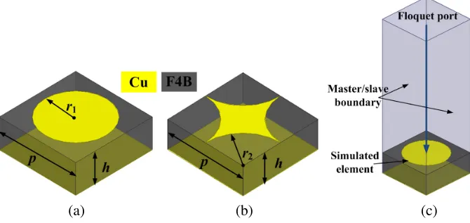
As shown in Fig. 1, two basic elements of the original MS both are composed of two copper films with a substrate of F4B (the period is 8 mm, the relative permittivity is 2.65 and the loss tangent is 0.001) between them. The difference between them lies in the top pattern, which is a circular patch for E1 with a star-like patch for E2. To insure the band of sufficient phase cancellation between two elements as wide as possible, Ansoft HFSS 14.0 is utilized to search the optimal physical dimensions, in which the master/slave boundary condition and Floquet port are adopted to simulate the situation of infinite periodic elements. As a result, the optimized results are r1 = 3.2 mm, r2 = 4 mm, h = 3 mm. Fig. 2 shows the reflection characteristics of E1 and E2, from which it can be observed that both the elements exhibit nearly total reflection for the normal incidence. Meanwhile, a wide sufficient phase cancellation band is obtained at the range of 8.4 GHz–18.5 GHz. Then, the original MS can be built up based on the two basic elements, as depicted in Fig. 3, where 4×4 elements construct a MS block for periodicity hold, and 9×9 MS blocks construct the whole MS array with a chessboard-like configuration. When illuminated by a normal plane wave, we can obtain the monostatic RCS of the original MS versus operating frequency, as shown in Fig. 4. In particular, only the case of x-polarization is provided due to the symmetrical structures of the two elements and the rotational symmetric layout. Additionally, to clarify the direction of polarization, the Cartesian coordinates are implanted in the figure, wherek0 represents the incidence direction. Compared to the metal with a same dimension, RCS of the original MS is obviously reduced at the whole observed band. However, the reduction is around merely 6-dB, and the 10-dB reduction band is too narrow to match the predictions of element simulation in Fig. 2.
(b)
(a) (c)
Figure 1. Perspective of two basic elements. (a) E1; (b) E2; (c) Simulation model.
6 8 10 12 14 16 18 20 0.995
0.996 0.997 0.998 0.999 1.000
Reflection Amplitued
Freq[GHz]
E1 E2
6 8 10 12 14 16 18 20 -180
-120 -60 0 60 120 180 240
Reflection Phase[deg]
Freq[GHz] Phase Difference E1
E2
(a) (b)
288mm
Ex Hy
k0 E2
E1
Figure 3. Schematic of original MS.
6 8 10 12 14 16 18 20 5
10 15 20 25 30
RCS[dBsm]
Freq[GHz] Metal Reference MS
Figure 4. Simulated RCS of original MS for the normal x-polarized waves.
2.2. Proposed Method and Analysis
In consideration of the problem stated above, we adopt a polar coordinate system to analyze the phase relationship between different elements, as shown in Fig. 5. Hence, reflectivity of the MS for the normal incidence can be expressed as:
r=
i
Pi·Ai·ejϕi
2
(1)
wherePi represents the area portion of each element in the MS array, Ai the reflection amplitude, and ϕi the reflection phase of each element.
As for the original MS composed of two elements in Fig. 5(a),
P1(41/81)≈P2(40/81)≈1/2, A1=A2 =A3 = 1, |ϕ1−ϕ2| ∈[150◦,210◦] (2) Substituting Equation (2) into Equation (1) provides the result of R ≤0.08 (nearly −11 dB). In particular, the result is based on the element reflection characteristics, while the phase relationship will be changed to some extent for the realistic MS array and resulting in higher reflectivity. In other words, once one of the phasors is fixed, the other has a free range of merely 60◦, which means that the phase relationship in Equation (2) is not universal enough. Therefore, a more universal case is proposed in Fig. 5(b), in which
P1=P2 =P3= 1/3, A1 =A2 =A3 = 1, |ϕ1−ϕ2| ≥180◦ (3)
(a) (b)
In this way, as long as the phasor of E3 lies in the green shadow region bounded by the oppositely elongated lines of other two phasors, meaning
|ϕ1−ϕ3| ≤180◦, |ϕ2−ϕ3| ≤180◦ (4)
the phasor sum of E1 and E2 will be dramatically counteracted due to the introduction of E3, and a result ofR≤0.11 (nearly −10 dB) can be obtained according to Equation (1). In summary, compared with Case I in Fig. 5(a), the condition of phase cancellation gets milder in the element analysis for Case II, and this is advantageous for achieving remarkable RCS reduction in broadband in the array simulation.
2.3. Design and Simulation of Proposed MS
To investigate if case II is superior to case I, we first design a structure of E3 depicted in Fig. 6, in which the top pattern is constituted by nine quadrate patches, and the value of a is 1.76 mm. The simulation method of E3 is in concordance with the one about E1 and E2 stated in Subsection 2.1. Fig. 7 synthetically gives the reflection characteristics of E1, E2 and E3, in which the value of r1 has been updated as 3.8 mm to satisfy the phasor relationship in Equation (3). From Fig. 7, it can be seen that the amplitude requirement in Equation (3) is approximately realized, and the reflection phase of E1 is shifted to lower frequencies compared to the original case. For better analysis of phase relationship among the three elements, the phase differences curves are provided in Fig. 8. Then, it can be clearly observed that the phase requirements in Equations (3) and (4) have been satisfied at the band region surrounded by green shadow, which predicts that nearly 10-dB RCS reduction can be achieved. Furthermore, to insure the condition of area portion satisfied, a lattice composed of the blocks of E1, E2 and E3 is first built up by placing them crosswise between each other. In particular, it can be found that the lattice possesses three arrangements, which have been marked in green, blue and orange in Fig. 9(b), respectively. Then, put the three arrangements in a cross configuration again to construct the final array of the proposed MS, as shown in Fig. 9. As a result, P1 =P2 =P3 = 1/3 and E3 has been effectively implanted on the MS array, by which a destructive interference can be expected between E3 and the other two.
Figure 6. Perspective of E3.
Afterwards, we give the full wave simulation results of the proposed MS, as depicted in Fig. 10. Similarly, the case ofx-polarization is provided because the curves ofx- andy-polarizations are almost coincident with each other, which could be attributed to the symmetrical structures of the elements. From Fig. 10, it can be seen that RCS of the proposed MS is further reduced by more than 3-dB from 6.7 GHz to 14.48 GHz compared to the original MS, and the maximum further reduction reaches 20.8 dB at 13.1 GHz. Additionally, compared with the same-size metal, a 10-dB RCS reduction band ranging from 6.42 GHz to 13.38 GHz (70.3% relative bandwidth) can be picked out from the curves. Although the 10-dB RCS reduction band gets narrow in the array simulation in contrast with the prediction in the element simulation, reduction values of the proposed MS are indeed obviously increased in broadband compared to the original one.
6 8 10 12 14 16 18 20 -180 -135 -90 -45 0 45 90 135 180 E1 E2 E3 Freq[GHz] Refleciton Phase[deg] 0.95 0.96 0.97 0.98 0.99 1.00 Reflecion Am p litude
Figure 7. Reflection characteristics of E1, E2 and E3.
6 8 10 12 14 16 18 20
0 45 90 135 180 225 270 3 1 ϕ − ϕ 2 3
ϕ − ϕ2 1 ϕ − ϕ
Phase Difference[deg]
Freq[GHz]
Figure 8. Phase differences between E1, E2 and E3.
Ex Hy
k0
E3 E1 E2
E1 E2 E3
E3
E2 E1
E3 E1 E2
E2 E3 E1
E3 E1 E2
E1 E2 E3
E3 E1 E2
E1 E2 E3
E3 E1 E2
E1 E2 E3
E3
E2 E1
E1 E2 E3
E3 E1 E2
E1 E2 E3
E1 E2 E3
E3 E1 E2
E1 E2 E3
E3 E1 E2
E1 E2 E3
E3
E2 E1
E3 E1 E2
E2 E3 E1
E3 E1 E2
E3 E1 E2
E2 E3 E1
E3 E1 E2
(a) (b)
Figure 9. (a) Geometry and (b) Specific layout of proposed MS.
6 8 10 12 14 16 18 20
-5 0 5 10 15 20 25 30 RCS[dBsm] Freq[GHz] Metal Reference MS Proposed MS
Figure 10. Simulated RCS curves for the normal x-polarized waves.
(a) (b)
Figure 11. Surface current distributions of (a) original MS and (b) proposed MS at 8.4 GHz.
the surface current strength is enhanced step by step for E3, E2 and E1, respectively, which indicates that a proper phase gradient for phase cancellation is generated among the three elements. Therefore, compared with the original MS, RCS reduction of the proposed MS is more conspicuous at 8.4 GHz.
3. EXPERIMENTAL RESULTS
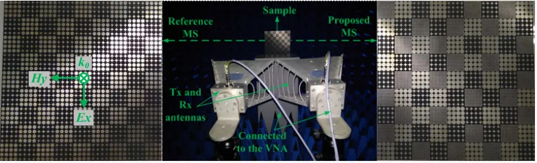
To verify the simulation results, scattering performances of the two MS samples are tested in an anechoic chamber, as depicted in Fig. 12, where the samples are placed in front of the horn antennas with a distance of 1.6 m to satisfy the condition of far-field test. The two antennas are connected to the two ports of vector network analyzer (VNA), and then the monostatic RCS of two samples for the normal x-polarized waves can be evaluated by the parameter ofS21. Additionally, the reverse side of the sample, which is a same-size metallic plate, is also measured as a contrast. Furthermore, to better eliminate the ambient noise in the chamber, the time-domain gate of VNA is adopted in the experiment.
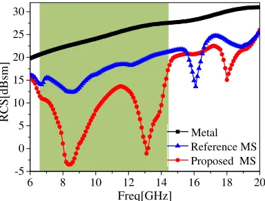
Confined by the operating frequency range of horn antennas, we can only give the measured RCS reduction curves of two samples at the range of 6 GHz–18 GHz, as shown in Fig. 13, in which the simulations are also imported for comparison. From Fig. 13, it can be noted that RCS of the proposed MS is apparently lower than the reference one at most frequencies, and 8.5-dB RCS reduction for the proposed MS is achieved at the range of 6.68 GHz–15.38 GHz with the relative bandwidth of 78.9%. Additionally, Fig. 14 gives the curve of further RCS reduction of the proposed MS compared with the reference MS, from which we can observe that RCS of the proposed MS is further reduced by at least 3-dB at the range of 6.94 GHz–15.35 GHz, and the peak value of further reduction reaches 24.9 dB. Meanwhile, we notice the frequency and reduction deviations between the simulations and measurements, which can be attributed to the machining errors, not perfectly standard plane waves radiated by the transmitting antenna, imprecise angle between samples and antennas, deflected phase center, etc. Even so, the favorable agreement between the simulation results and the experiments
Ex k0
Hy
6 8 10 12 14 16 18 0
6 12 18 24 30 36
8.5RCS Reduction[dB]
Freq[GHz]
/ Simulated reference/proposed MS / Measured reference/proposed MS
Figure 13. Measured RCS reduction of samples under the normalx-polarization.
6 8 10 12 14 16 18
0 6 12 18 24
RCS Reduction[dB]
Freq[GHz]
Figure 14. Measured further RCS reduction of proposed MS compared with the reference MS.
confirms the availability of the proposed method, by which RCS of the MS can be obviously reduced in broadband due to the destructive interference of introducing element with the phasor sum of the other two.
Lastly, the comparison between the work in this paper and current similar works is shown in Table 1. Although RCS reduction of the MS proposed in this paper is slightly smaller than the references, the proposed MS can achieve RCS reduction in broader band than the others. Moreover, it can be seen that the fractional bandwidth in [20] is nearly equal to the one in this paper. However, compared to the thickness of 3 mm (0.1λat 10 GHz) of the proposed MS, the MS in [20] is based on a double-layer structure with the thickness of 4.81 mm (0.16λ at 10 GHz), which goes against the performance of low profile.
Table 1. Comparison between this work and current similar works.
Similar works Ref. 17 Ref. 21 Ref. 22 Ref. 24 Ref. 26 This work
RCS reduction for the normal
incidence
10-dB 10-dB 10-dB 10-dB 10-dB 8.5-dB
Bandwidth 0.7–1.3 THz
(60%)
7–12 GHz (52.6%)
5.9–12.7 GHz (73%)
0.8–1.5 THz (60.9)
5.26–6.8 GHz (25.5%)
6.68–15.38 GHz (78.9%)
4. CONCLUSION
In this paper, we have proposed an efficient method to achieve further RCS reduction on the MS composed of two elements. By introducing a phasor interference element to the MS effectively, a lower-scattering feature of new MS can be obtained over a broadband, and the idea is verified by the results of both simulation and measurement. In a word, this design provides a novel train of thought for researchers to design the metasurface with property of wideband low RCS.
ACKNOWLEDGMENT
REFERENCES
1. Chu, C. H., M. L. Tseng, J.Chen, P. C. Wu, Y. H. Chen, H. C. Wang, T. Y. Chen, W. T. Hsieh, H. J. Wu, G. Sun, and D. P. Tsai, “Active dielectric metasurface based on phase-change medium,”
Laser Photonics Rev., Vol. 10, No. 6, 986–994, 2016.
2. Zhang, H. F., M. Kang, X.Q. Zhang, W. G. Guo, C.G. Lv, Y. F. Li, W. L. Zhang, and J. G. Han, “Coherent control of optical spin-to-orbital angular momentum conversion in metasurface,” Adv. Mater., Vol. 29, 1604252, 2017.
3. Xie, B. Y., K. Tang, H. Cheng, Z. Y. Liu, S. Q. Chen, and J. G. Tian, “Coding acoustic metasurfaces,” Adv. Mater., Vol. 29, 1603507, 2017.
4. Li, H. P., G. M. Wang, J. G. Liang, X. J. Gao, H. S. Hou, and X. Y. Jia, “Single-layer focusing gradient metasurface for ultrathin planar lens antenna application,”IEEE Trans. Antennas Propag., Vol. 65, No. 3, 1452–1457, 2017.
5. Gonz´alez-Ovejero, D., G. Minatti, G. Chattopadhyay, and S. Maci, “Multibeam by metasurface antennas,”IEEE Trans. Antennas Propag., Vol. 65, No. 6, 2923–2930, 2017.
6. Sievenpiper, D., L. J. Zhang, R. F. J. Broas, N. G. Alex’opolous, and E. Yablonovitch, “High-impedance electromagnetic surfaces with a forbidden frequency band,” IEEE Trans. Microw. Theory Tech., Vol. 47, No. 11, 2059–2074, 1999.
7. Paquay, M., J. C. Iriarte, and Ederra, “Thin AMC structure for radar cross-section reduction,”
IEEE Trans. Antennas Propag., Vol. 55, No. 12, 3630–3638, 2007.
8. Gao, L. H., N. Xiang, J. Zhao, D. S. Dong, K. Wang, and Q. Cheng, “A low RCS metasurface for THz applications,”IEEE 3rd Asia-Pacific Conference on Antennas and Propagation(APCAP), 1279–1281, Harbin, China, 2014.
9. Yang, Y. H., L. Q. Jing, B. Zheng, R. Hao, W. Y. Yin, E. P. Li, C. M. Soukoulis, and H. S. Chen, “Full-polarization 3D metasurface cloak with preserved amplitude and phase,”Adv. Mater., Vol. 28, 6866–6871, 2016.
10. Yang, Y. H., H. P. Wang, F. X. Yu, Z. W. Xu, and H. S. Chen, “A metasurface carpet cloak for electromagnetic, acoustic and water waves,” Scientific Reports,Vol. 6, 20219, 2016.
11. Landy, N. I., S. Sajuyigbe, J. J. Mock, D. R. Smith, and W. J. Padilla, “Perfect metamaterial absorber,” Phys. Rev. Lett., Vol. 100, No. 20, 207402, 2008.
12. Yahiaoui, R., J. P. Guillet, F. de Miollis, and P. Mounaix, “Ultra-flexible multiband terahertz metamaterial absorber for conformal geometry applications,”Optics Letters, Vol. 38, No. 23, 4988– 4990, 2013.
13. Yahiaoui, R., K. Hanai, K., Taakano, T., Nishida, F. Miyamaru, M. Nakajima, and M. Hangyo, “Trapping waves with terahertz metamaterial absorber based on isotropic Mie resonators,” Optics Letters, Vol. 40, No. 13, 3197–3200, 2015.
14. Yahiaoui, R., S. Tan, L. Cong, R. Singh, F. Yan, and W. Zhang, “Multispectral terahertz sensing with highly flexible ultrathin metamaterial absorber,”Journal of Applied Physics, Vol. 118, No. 8, 083103, 2015.
15. Pan, W. X. Yu, J. Zhang, and W. Zeng, “A broadband terahertz metamaterial absorber based on two circular split rings,”IEEE Journal of Quantum Electronics, Vol. 53, No. 2, 8500206, 2017. 16. Nouman, M. T., J. H. Hwang, and J. H. Jang, “Ultrathin terahertz quarter-wave plate based on
split ring resonator and wire grating hybrid metasurface,” Scientific Reports, Vol. 6, 39062, 2016. 17. Liang, L. J., M. G. Wei, X. Yan, D. Q. Wei, D. C. Liang, J. G. Han, X. Ding, G. Y. Zhang, and
J. Q. Yao, “Broadband and wide-angle RCS reduction using a 2-bit coding ultrathin metasurface at terahertz frequencies,”Scientific Reports, Vol. 6, 39252, 2016.
18. Yang, H. H., X. Y. Cao, F. Yang, J. Gao, S. H. Xu, M. K. Li, X. B. Chen, Yi Zhao, Y. J. Zheng, and S. J. Li, “A programmable metasurface with dynamic polarization, scattering and focusing control,” Scientific Reports, Vol. 6, 35692, 2016.
20. Wan, X., M. Q. Qi, T. Y. Chen, and T. J. Cui, “Field-programmable beam reconfiguring based on digitally controlled coding metasurface,” Scientific Reports, Vol. 6, 20663, 2016.
21. Song, Y. C., J. Ding, C. J. Guo, Y. H. Ren, and J. K. Zhang, “Ultra-broadband backscatter radar cross section reduction based on polarization-insensitive metasurface,” IEEE Antennas Wireless Propag. Lett., Vol. 15, 329–331, 2016.
22. Mighani, M. and G. Dadashzadeh, “Broadband RCS reduction using a novel double layer chessboard AMC surface,”Electronics Letters, Vol. 52, No. 14, 1253–1255, 2016.
23. Li, Y. F., J. Q. Zhang, S. B. Qu, J. F. Wang, H. Y. Chen, Z. Xu, and A. X. Zhang, “Wideband radar cross section reduction using two-dimensional phase gradient metasurfaces,” Appl. Phys. Lett., Vol. 104, 221110, 2014.
24. Yan, X., L. j. Liang, J. Yang, W. W. Liu, X. Ding, D. G. Xu, Y. T. Zhang, T. J. Cui, and J. Q. Yao, “Broadband, wide-angle, low-scattering terahertz wave by a flexible 2-bit coding metasurface,”
Optics Express, Vol. 23, No. 22, 29128–29137, 2015.
25. Wang, K., J. Zhao, Q. Cheng, D. S. Dong, and T. J. Cui, “Broadband and broad-angle low-scattering metasurface based on hybrid optimization algorithm,” Scientific Reports, Vol. 4, 5935, 2014.
26. Zhao, Y., X.Y. Cao, J. Gao, X. Yao, T. Liu, W. Q. Li, and S. J. Li, “Broadband low-RCS metasurface and its application on antenna,” IEEE Trans. Antennas Propag., Vol. 64, No. 7, 2954–2962, 2016.