a
Experimental study of submillimeter droplets dynamics and breakup in
continuous supersonic flow terminated by shock wave
Oleg Gobyzov1,2, Yuriy Lozhkin1,2, Mikhail Ryabov1,2 and Dmitriy Markovich 1,2
1
Kutateladze Institute of Thermophysics, Siberian Branch of Russian Academy of Sciences, 630090, Novosibirsk, Russia
2
Novosibirsk State University, 630090, Novosibirsk, Russia
Abstract. The present paper reports an application of optical methods, namely PIV, background-oriented-schlieren (BOS) and high-magnification imaging with background illumination to study of dynamics and breakup of 10-100 m size droplets in continuous supersonic flow terminated by a normal shock wave. Flow diagnostics was performed by means of BOS and PIV. Shadow photography allowed to specify velocity ranges for different droplet sizes and to visualize droplets dynamics and breakup modes. Features of the experimental setup and certain details of implemented measurement system are considered. Results of velocity measurements and droplets behavior, including deformation and breakup, are presented and analysis of experimental conditions and dimensionless parameters affecting the droplets behavior is performed. Distinctive features of deformation and breakup processes of submillimeter scale droplets are revealed.
1 Introduction
Investigation of liquid drops deformation and breakup in high-speed flows has many scientific and technological applications: combustion of liquid fuels, erosion of steam turbine blades, cold spray processing and others. Through the last several decades a large number of experimental works, aimed on identification of droplets atomization regimes, systematization of amassed information and revealing of influencing parameters were performed. In this investigations it was shown that atomization of liquid droplets due to aerodynamic forces is a complex process that involves different physical mechanisms depending on the experimental conditions. Generally speaking it is considered that dynamics and breakup of liquid drops are governed by such dimensionless parameters as Weber number (We), Ohnesorge number (Oh) and Eötvös or Bond number (Bo), certain effect may also occur due to variation of Reynolds number (Re) [1]. Usually magnitudes of transitional Weber numbers considered to be quite stable for Oh<0.1, while for higher Oh increase in transitional We is observed [2]. Nevertheless, critical values of these parameters differ significantly from one paper to another.
Most part of the published works deal with the drops of size 1 mm (see e.g. [3, 4]). One of the main reasons for this is that study of smaller droplets is more challenging task, at least from the technical point of view. Besides that, one can usually choose a combination of dimensionless parameters to model the required conditions and to preserve separate parameters in the suitable range. At the same time there is still a place for
presupposition that for small-scale droplets processes of deformation and breakup may have significant differences from those for millimetre-scale drops. First of all, such presuppositions are based on the fact that We and Re numbers cannot be preserved together with the decrease of the droplets size without variation of gas or liquid characteristics. More “intuitive” basis is that for the droplets of tens of micrometers size surface tension and capillary effects should play more important role. However, for the droplets less than 100 m in diameter there is limited amount of experimental data on dynamics and breakup of droplets in gas flows and retrieving such data requires application of advanced experimental techniques.
In the present work several optical measurement methods, among which are particle image velocimetry (PIV), background-oriented schlieren (BOS) and high-magnification imaging with background illumination (shadow photography, SP) were applied to study dynamics and breakup of submillimeter droplets in continuous supersonic flow with normal shock wave. Results of flow and droplets velocity measurements and visualization of particle behaviour, including deformation and breakup, are presented.
2 Setup and measurement techniques
EPJ Web of Conferences
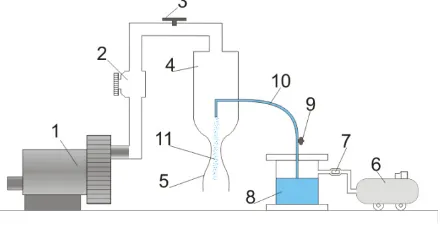
the regenerative blower through the pressure regulator (fig. 1) at the rate of 35 l/s. Air flow conditions, namely pressure and temperature, were measured in the plenum chamber. The nozzle was operated in underexpanded regime to produce a normal shock wave (SW) in the diverging section of the nozzle.
Figure 1. Scheme of the setup. 1 – air blower, 2 – pressure regulator, 3 – valve, 4 – plenum chamber, 5 – nozzle, 6 – compressor, 7 – electronic pressure regulator, 8 – water tank, 9 – valve, 10 – water supply tube, 11 - droplets.
Droplets were introduced into the flow by atomization of the coaxial liquid jet issued from the tube with diameter of 0.8 mm. Exit of the tube was fixed in the plenum chamber upstream of the converging part of the nozzle. Visualization of the jet atomization was performed to determine an atomization regime and size of the resulting droplets. So called fiber atomization regime [5] was observed with formation of large clusters at the distance of 3-5 mm from the tube exit. At the distance of 10-12 mm downstream of the tube exit an atomization was finished in general, although small amount of liquid ligaments still persisted in the flow. The size of resulting drops mainly varied in the range from 10 m to 100 m.
To fetch an image of a submillimeter droplet in a supersonic flow a high spatial resolution and short exposure of the recording system are required. Usually cameras, except for the ICCD, do not provide enough shutter speed and sensitivity to perform such visualization and thus high-energy and short duration (order of nanoseconds) light pulses are required for background lighting. An Nd:YAG pulse laser fits these requirements but due to coherent nature of emitted light it introduces small-scale speckles that deteriorate the image quality. In the current work a fluorescent background screen was used to provide an even background lighting without speckles. Fluorescent layer was excited by the 532 nm wavelength pulsed light beam generated by dual-head Nd:YAG laser. The size of the area excited by the laser light was adjusted using the diverging lens placed in an optical path of the laser beam.
To provide a required optical magnification an Infinity K2/SC long distance microscope was used as a camera lens. An optical magnification of 4.3:1, that is
1.6 m/pix, was reached at the distance of 200 mm from the measurement area. Owing to 5 ns laser pulse duration and short Rhodamine B fluorescent paint lifetime ( 2-3 ns) droplet displacement during the exposure time didn’t exceed 2 m and practically «frozen» images of droplets were captured. Using dual-head laser and CCD-camera in double-frame exposure
mode pairs of images with different interframe delay were captured in experiments. A certain disadvantage of this method of visualization was that the depth-of-field provided by the microscope was of the same order as the droplet size and therefore large number of fully or partially out-of-focus droplets were present in the images.
To measure gas and droplets velocity PIV technique was employed. The drawback of the technique for the case was that images of droplets were much brighter than the images of PIV tracers and therefore contributed most to the correlation function. No image filtering procedures were effective enough to eliminate droplets contribution to the correlation function, so droplets and gas velocity were measured in separate experiments. Water-glycerol tracer particles of the size 1 m produced by the Laskin-nozzle type generator were introduced into the air supply line immediately after the pressure regulator. From the instant velocity field it was evaluated that tracer relaxation length at the shock wave front is about 2 mm, and thus velocity data immediately after the shock wave front was overestimated. For the measurements of droplets velocity no droplet size separation was made and only average liquid phase velocity was measured. Obviously, drops acceleration depends on its size and shape, so manual evaluation of velocity for droplets of different size was performed. At the distance of 3 mm upstream of the SW front, where velocity dispersion for droplets of different size should be close to maximum, average velocity of 40-m droplets was 285 m/s, while for 15- m droplets it amounted to 320 m/s. Gas and droplets velocity distribution is presented in fig. 3.
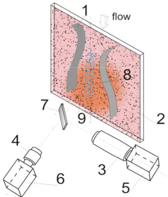
Figure 2. 1 – nozzle walls, 2 - fluorescent screen, 3 – LD microscope, 4 – camera lens, 5,6 – cameras, 7- half-transparent mirror, 8 – droplets, 9 – area of the screen excited by laser emission
In a case of shadow photography application for visualization of small-scale objects with short exposure time a proper distance between the fluorescent screen and measurement plane should be chosen: shorter distance yields brighter image but may lead to blurred edges in it, while longer distance yields sharper image but reduces an amount of light collected by the camera lens. Difference in image quality can be seen from fig. 3. In the experiments the distance between the fluorescent screen and measurement plane was 170 mm.
Figure 3 Sample fragment of the SP droplets image. a – with the screen at the distance of 25 mm from the measurement area. b – at the distance of 170 mm
3
Flow diagnostics
Figure 4.Gas average velocity distribution (a), gas and droplets velocity profile along axis of symmetry (b), background screen with random pattern and instantaneous result of BOS visualization (c)
PIV measurements have shown a smooth acceleration of the air flow with step deceleration (shock wave) inside the diverging part of the nozzle at the distance of approximately 20 mm from the nozzle throat (fig. 4, 4b). Although the structure of the flow before the shock wave front remained the same during the experiment, oscillations of the shock wave front position and variations of the velocity were observed. BOS visualization (see fig. 4c) revealed that the shock wave front fluctuated within the range of ± 1.5 mm from its average position. Maximum velocity immediately before the step deceleration varied approximately from 570 to 620 m/s. Such instability is most likely due to non-stationary flow conditions downstream of the shockwave front: a secondary acceleration with a signs of flow separation and re-attachment near the wall was observed.
Droplets also exhibited smooth acceleration along the whole measurement area, but significantly lagged behind the gas flow. Eventually, droplets velocity before the SW front was close to the gas velocity after the step deceleration, and thus impact of the aerodynamic forces on droplets decreased abruptly immediately after the SW front.
b
a
b
c
EPJ Web of Conferences
Droplets deformation and breakup
Images of droplets were captured in the vicinity of the average shock wave front position and at the distances up to 15 mm upstream and downstream of it with a step of 3 mm. 300 pairs of images were obtained for each measurement area. Pairs of images were taken with interframe delay of 800 ns, 1500 ns and 2800 ns – 100 of image pairs for each delay value.
Due to the presence of out-of-focus particles and particles in a state of breakup it was virtually impossible to automate droplets images identification and sizing so image processing was performed manually. Due to this rather small number of droplets for each area of visualization (100-150 droplets) was accounted in statistics. Only drops retaining spherical shape or shape close to elliptical were taken into account. Eventually, droplets size and shape were evaluated from the images
Average droplets size, i.e. an average diameter of a sphere of equal volume
2 3
x y
d
=
a a
(1)where ax is a streamwise ellipse dimension and ay – transversal ellipse dimension, was 20-26 m in a whole measurement area. Droplets exhibited streamwise contraction before the shock wave front and extension immediately after the shockwave front, yet, generally droplets extension and contraction rate for mentioned sizes did not exceed 30%, which is insufficient for transition to breakup.
From qualitative analysis of the captured images a few preliminary conclusions could be made: despite the fact that most intense impact of aerodynamic forces on droplets obviously should be immediately before the SW front, most part of the droplets in a state of disruption was observed at the distance of 15 – 9 mm upstream of the average SW front position. Closer to the SW front elliptical small droplets and “fibers” were mainly observed.
To interpret the obtained results range of dimensionless parameters affecting the droplets dynamics and breakup was estimated for several droplet sizes (see table. 1). Maximum droplets velocity lag vmax300 m/s was observed immediately before the shock wave front, so this value was substituted for estimation. A characteristic time of breakup induction,
1 2 * v d g d t ρ ρ § · =Δ ¨¨ ¸¸ © ¹ (2)
where v – velocity difference between droplet and gas,
ȡd – droplets density and ȡg – density of gas, is also specified for different sizes of droplets in table 1.
Ohnesorge number for droplet sizes d>1 m is below critical value of 0.1, above which Weber numbers demarking breakup mode boundaries tend to grow with increase of Oh. For droplets of 15 m in diameter We was definitely below the critical value, while for droplets larger than 20 m in diameter it was in the range, which is usually referred as a range of bag-breakup regime [3, 6]. However, it is considered that gradual acceleration leads to increase in critical We numbers demarking
breakup modes [7], and thus We14 for 30-m droplets should be regarded as «transitional», yet droplets with diameter d40÷50 m, according to [8] should exhibit breakup.
Table 1. Typical values of characteristic parameters
droplet size
[m] 15 30 50
Weber number
(We) 10,6 21.2 35.4
Ohnesorge
number (Oh) 2.810 -2
210-2 15.610-2
Laplace
number(La) 1.210 3
2.5103 4.1103
Reynolds
Number (Re) 130 260 435
t*[s] 2.110-6 4.310-6 7.110-6
Contrary to these arguments, experiments have shown that droplets in a range of sizes from 10 m to approximately 35 m stably persisted in the flow upstream and downstream of the shock wave front. Such droplets exhibited shape oscillations, i.e. contraction in the continuous flow and elongation in the vicinity of the SW front, but did not display any clear tendency for breakup.
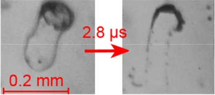
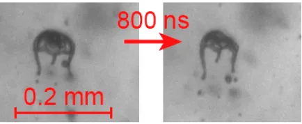
For larger droplets well-known breakup regimes – vibrational and bag breakup modes ([6, 7]) were detected in the area of flow acceleration (see fig. 5). Immediately after the shock wave front only final stages of such breakup regimes were observed. As the method of visualization allowed to fetch only pairs of subsequent “snapshots” of the breakup process but not the whole process in dynamics, interpretation of images with droplets in a state of disruption, especially evaluation of their initial size, was significantly hindered. Further to mentioned “classic” regimes in some rare cases distinct dual bag breakup, described by Cao et. al. [8] also occurred (see fig. 6).
Figure 5 Example of developed bag breakup mode. Downward flow direction.
Figure 6 Example of dual-bag breakup regime. Downward flow direction.
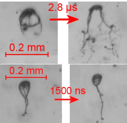
Worth noting is the fact that final stages of the breakup observed in the experiments differ from those described in papers by Wierzba [7], Guildenbecher [6] and others. Although small number of large, fully developed “bags” that exhibited explosive type of disruption with formation of large number of small drops were detected (as in fig 5. and fig. 7), much more often after the rupture of the “bag” film pieces attached to the rim, formed elongated fibers that persist in a flow for a long time (see fig. 8).
Figure 7 Example of bag breakup with formation of small droplets. Flow direction from left to right.
Another observation regarding the bag formation and breakup is that interruption of “bag” development was repeatedly observed in experiments. In the case of such interruption an undeveloped, usually asymmetric small bag breaks with formation of fiber-type structure An example of such process is shown in fig. 9. Generally speaking it is quite hard, if possible at all, to formally distinguish fully developed bag disruption from the interrupted one, but in the limiting cases difference is obvious and captured images give an impression that only very large bags disrupt in explosive manner. Presumably surface tension together with some local flow disturbances (turbulent pulsations) interrupts bag growth, yet there is no any strong evidence to support such explanation.
Figure 8. Example of bag rupture with formation of several fibers (up) and merging of fibers (down). Downward flow direction.
Figure 9. Example of vibrational breakup with formation of long connecting fiber. Downward flow direction.
Similar process occur for the vibrational breakup: droplet transforms into two smaller drops connected by a long fiber and then one of the smaller droplets detach from the formation, while another still persist in a flow with an attached fiber. In some cases such fibers can extend to the length close to 1 mm and, apparently, contain the considerable part of the droplet initial mass. Example of such breakup is shown in fig. 10.
Figure 10. Example of vibrational breakup with formation of long connecting fiber. Downward flow direction.
EPJ Web of Conferences
Figure 11 Example of transitional breakup mode. Downward flow direction.
As for the characteristic time of breakup, according to [1] it amounts to 5t* for the bag-breakup mode, and
2t* for vibrational breakup [1]. For such small droplets as were observed in the experiments t* is amounted to microseconds, and the displacement of the droplet during this time is of order of 1 mm. This means that all the breakup processes induced by aerodynamic forces should be finished upstream the shock wave front. Indeed, in the images taken at the distance of 6, 9 and 12 mm downstream of SW front droplets, on the average, retained spherical shape. Besides, breakup visualization in dual-frame regime confirms that this characteristic time estimation remains valid, at least in the order of magnitude, for submillimetre-scale droplets.
A behaviour of submillimetre-scale water droplets in a continuous transonic – supersonic flow terminated by normal shock wave was investigated using set of optical techniques, namely: PIV, PTV, BOS and shadow photography.
In general, it was found that small-scale droplets undergo breakup processes at slightly elevated We comparing to the “large” drops: no clear evidences of droplets breakup at the We<25 (diameter<35) were detected.
Larger droplets exhibited well-known vibrational and bag breakups and dual-bag disruption. Such breakup modes often resulted in formation of long “fibers” instead of large number of small drops. This effect is most likely due to the greater role of surface tension, which prevents immediate atomization of such “fibers”.
Certain detected types of “transitional” breakup regimes could not be directly associated with any of regimes described in literature. Also different types of breakup realized for very similar droplet sizes. This conforms to a statement by Wierzba [7] that droplet behavior is extremely sensitive to the flow conditions and thus may vary significantly in one and the same flow configuration. Experimental results have also confirmed that characteristic breakup time estimation remains valid, at least in the order of magnitude, for the submillimetre-scale droplets.
Acknowledgements
Thework was supportedby RussianFoundation for Basic Research (grant number 14-08-31718).
References
1. R.I. Nigmatulin Dynamics of Multiphase Media, 1. N.Y.: Hemisphere,. 507 p., (1991)
2. G.M. Faeth, L.P. Hsiang, P.K. Wu, Int J Multiphase Flow 21 (Suppl),:99 (1995)
3. V.M. Boiko, A.N. Papyrin, S.V. Poplavskii, Journal of Applied Mechanics and Technical Physics. 28. I. 2, 263 (1987)
4. M. Pilch, C.A. Erdman, Int. J. Multiphase Flow 13, 741 (1987)
5. J.C. Lasheras, E.J. Hopfinger, Ann. Rev. J. Fluid Mech. 32, 275 (2000)
6. D.R. Guildenbecher; C.López-Rivera, P.E. Sojka, Exp. Fluids 46, 371 (2009)
7. A. Wierzba, Exp. Fluids 9, 59 (1990)
8. X.K. Cao, Z.G. Sun, W.F. Li, H.F. Liu, Z. H. Yu, Phys. Fluids 19 (5): 057103, (2007)
9. T. Kekesi, G. Amberg, L.P. Wittberg, Journal of Multiphase Flow 66, 1 (2014)