A STATCOM Model for Optimal Power
Flows Using Genetic Algorithm
P. Dhivya1, G. Sundarrajan2
PG Student [PSE], Dept. of EEE, JJ College of Engineering, Tiruchirappalli, Tamilnadu, India1
Assistant Professor, Dept. of EEE, JJ College of Engineering, Tiruchirappalli, Tamilnadu, India2
ABSTRACT:This paper presents the optimal power flow (OPF) formulation of STATCOM model. The new model puts forward an alternative, insightful interpretation of the fundamental frequency operation of the PWM-controlled voltage source converter (VSC), in an optimal fashion. The new model makes provisions for the explicit representation of the converter’s internal ohmic and switching losses which in the context of an OPF formulation, yields an optimum operating point at which these power losses are at a minimum. The STATCOM equations are incorporated into the OPF formulation using jacobian matrix functions in quite a natural manner for efficient optimal solutions using a single frame-of-reference. The prowess of the new model is demonstrated using two sample systems
KEYWORDS: FACTS, Genetic algorithm, optimal power flows, STATCOM, voltage source converter.
I.INTRODUCTION
Many optimization techniques have been used to solve OPF problem. They are Linear Programming (LP), Non Linear Programming (NLP), Quadratic Programming (QP), Newton-based solution and Interior Point (IP) methods. Alsac and Stott [1] introduced optimal power flow concept, then in Clements, et al. [2] tried to find minimum generating cost and losses in the power system, using Newton’s power flow, Lagrangian multipliers, gradient method and penalty method for soft limited inequality constraints. Alsac and Stott [1] improved the Dommenl and Tinney work by incorporating new constraints for steady state security. They analysed OPF, with and without outage condition and considering security in both case is presented in a neat way to understand in detail.
Intelligent optimization algorithms used to solve OPF are listed in this section. Anastasios G. Bakirtzis, et al. [3] used Enhanced Genetic Algorithm (EGA) to solve OPF, which is Binary coded GA. Number of bits in the chromosome is reduced to enhance the performance of the algorithm. Combined Economic Emission Dispatch problem are discussed in the following literatures. Abido [4] used Niched Pareto Genetic Algorithm (NPGA).
Non dominated Sorting Genetic Algorithm (NSGA) and Strength Pareto Evolutionary Algorithm (SPEA) to solve Environmental Economic Dispatch (EED). Hariharan T. and Gopalakrishnan M. [5] used to solve the Optimal Reactive Power Flow with the Facts Devices and considered the equipment limits. In Fuel Cost function valve point loading was ignored. Gnanadass, et al. [6] used DE algorithm to solve PF. Mandal KK., et al. [7] used Multi Objective Differential Evolution (MODE) algorithm to solve Environmental Economic Power Dispatch (EEPD) problem. In this work small population is considered to get optimal solution to achieve external pareto-optimal solution is used. Hemamalini S., et al. Used [8] DE technique into Sequential Quadratic Programming (SQP) to improve the performance of proposed algorithm. In this algorithm SQP is used to generate initial population for DE, these initial population individuals are nearer to optimal.
II. STATCOM MODEL
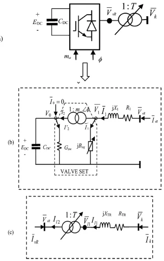
The STATCOM consists of two main components a voltage source converter (VSC) and a tap-changing coupling trans-former (LTC), as illustrated in Fig. 1(a). The VSC is modelled as an ideal complex tap-changing transtrans-former, shown in Fig. 1(b). The equivalent electric circuit for the STATCOM model is shown in Fig. 1.
The reason for using a complex tap changer to model the VSC operation stems from the following fundamental relationship applicable to the PWM controlled operation of the VSC:
1 = ma’ e3 DC
Fig. 1. (a) STATCOM schematic representation. (b) Voltage source converter equivalent circuit. (c) On-load tap-changing transformer equivalent circuit.
Where tap magnitude ma’ of the ideal complex tap-changing transformer corresponds to the amplitude
modulation coefficient of an actual two-level, three-phase VSC, defined as
ma’= √ , (1)
In which the PWM-controlled VSC operates in the linear range with 0 < < 1 [9]. The phase angle is the phase angle of the complex voltage 1 relative to the system phase reference. It should be noted that such aggregated relationships are also applicable to represent the fundamental frequency operation of three-level, three-phase VSC driven by PWM control since in This application the interest is in the relationship between DC and through ma and .
This would be regardless of the number of switches and converter levels. On the other hand, modular multilevel converters (MMC) have a different construction design and operating principles than PWM-driven converters.
value of Edc then the constant input DC voltage in each leg of a three-phase MMC-VSC with N sub-modules would be
EDC = N×Edc [10], [11]. It follows that the number of active N sub-modules in the multi-level converter dictates the
value of the voltage magnitude on the AC side of the converter. It turns out that (1) also represents very well the aggregated affects of this operation if one thinks of as a discrete tap as opposed to the continuous tap associated with the PWM-driven VSC converters. For numerical efficiency within the power flow the OPF solution a continuous tap is
assumed and at the end of the convergent solution, the nearest physical tap is selected and one further iteration is carried out to fine tune the overall power flow solution. This would not be different to schemes adopted elsewhere for the tap selection of LTC transformers where discrete taps are considered as opposed to continuous ones.
III. STATCOM AND ITS CONTROL SYSTEM
The Static Synchronous Compensator (STATCOM) [12] is a shunt connected reactive compensation equipment which is capable of generating and/or absorbing reactive power whose output can be varied so as to maintain control of specific parameters of the electric power system. The STATCOM basically consists of a step-down transformer with a leakage reactance, a three-phase GTO or IGBT voltage source inverter (VSI), and a DC capacitor.
The AC voltage difference across the leakage reactance produces reactive power exchange between the STATCOM and the power system, such that the AC voltage at the bus bar can be regulated to improve the voltage profile of the power system, which is the primary duty of the STATCOM. The basic structure of a STATCOM with PWM-based voltage controls is depicted in Figure 1.Eliminating the dc voltage control loop on this figure would yield the basic block diagram of a controller with typical phase angle controls.
The per-unit differential- algebraic equations corresponding to this model are:
ẋ
∝̇
ṁ
= f ( xc, α, V , Vdc, Vref, V ) (2)
Vdc ̇ = cos (δ−θ)− V − (3)
0 = g (∝, k, V, , Vdc,δ,I,θ ,P,Q) (4)
Where the admittance G + jB = ( + ) is used to represent the transformer impedance, any ac series filters, and
the “switching inertia” of the inverter due to its high frequency switching. The constant
K= m, (5)
Is directly proportional to the pulse width modulation index m and XC represents the internal control system variables. The ac bus voltage magnitude is controlled through the modulation index m, since this has a direct effect on the ac side
voltage source inverter (VSI) voltage magnitude. But the phase angle, α which basically determines the active power P flowing into the controller is used to directly control the dc voltage magnitude since the power flowing into the controller charges and discharges the capacitor. The controller limits are defined in terms of the controller current limits which are directly related to the switching device current limits, as these are the basic limiting factor in VSI-based controllers. In simulations, these limits can be directly defined in terms of the maximum and minimum converter currents, Imax (ILmax) and Imin (ICmax) respectively.
IV. GA-OPF WITH STATCOM
GA algorithm uses advantage to find global optimal value. In this algorithm GA selection, crossover is chosen and mutation, maximum generation is considered as stopping criteria. This fusion of algorithms provides best solution as compared to individual algorithms.
Initialization
Initial values of these genes are chosen randomly using a random number generated by MATLAB software as per the below Equation.
Pop = [Y1, Y2 . . . Ynp] (6)
Y = [Gene1, Gene2 . . . Gene15] (7)
Gene = Genemin+ η. (Genemax – Genemin) (8)
Where, Pop - Population Y - Chromosome np - Population size Genemax, Genemin - Gene maximum and minimum
limit η - Random number within [0 1]
Selection
Selection is the process of choosing high fitness chromosome to the mating pool. In this hybrid algorithm versatile Roulette Wheel selection is used.
Crossover
Crossover is the process of sharing vital information among the fittest chromosomes in the mating pool. Single point crossover is used in this hybrid algorithm.
Mutation
To improve mutation process, and it is carried out for all chromosomes in the population. A selected chromosome for mutation is called target vector, apart from target vector three more distinct chromosomes are selected to perform mutation. The model of OPF based on GA Algorithm. In this approach DE/rand/1 rule is used, and it is achieved by adding the weighted difference of two randomly selected vectors as given in Equation
The Genetic Algorithm technique uses a high efficient optimization technique to solve the issues and the speed is high and stability is easily done within a certain set of iterations. The genetic algorithm uses the fitness functions crossover mutation and elimination.
The power flow equations are used to calculate the real and reactive power calculations. The real and reactive power are known in the load bus while the angle and voltage magnitude is not known while in PV bus the real power and the voltage magnitude is known but the angle is not known. The genes in GA are elements which attains certain attributes and characteristics. Depending on the importance of the issue various parameters are selected as parameters for the gene. In UPFC the issues are power stability, voltage injection and loss minimization.
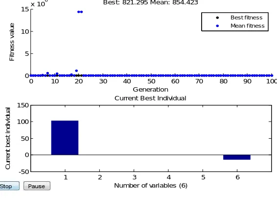
Fig. 2 GA-OPF
0 10 20 30 40 50 60 70 80 90 100
0 5 10 15x 10
6 Generation F it n e s s v a lu e
Best: 821.295 Mean: 854.423
1 2 3 4 5 6
-50 0 50 100 150
Number of variables (6)
C u rr e n t b e s t in d iv id u a l
Current Best Individual
This section provides numerical results of OPF solved by Genetic Algorithm (GA). This GA algorithm includes STATCOM for the optimization. This STATCOM need two control variables for the optimization namely its location and size. Considered test system has 4 transformers and 6 generators including slack, hence 5 real powers generation (PG) except slack bus, 6 generators voltage magnitude (VG) and 4 transformers tap position, STATCOM location and STATCOM size to the total 6 variables are taken as control variables. All these control variables have real value bounded between lower and upper limits are considered to code GA. It has 17 genes for a chromosome, 20 such chromosomes forms the population. This population is evolving iteration by iteration to find global optimal solution. The maximum number of iteration it may evolve is taken as 30 iterations. Crossover and mutation constants are taken as 0.7 and 0.01 respectively. Results of GA used to solve OPF with STATCOM are given below. From the Figure 2 it is clear that the generation of OPF with STATCOM is less as compare to base case and which gives reduced generating cost. Slack generator contributes more for real power generation and 4th generator contribution is less as compared to others. After connecting STATCOM the results are improved, the generating cost is reduced and loss is reduced as given in the Table.
V. SIMULATION RESULTS
To assess the accuracy, flexibility and robustness of the proposed STATCOM model, test cases are presented in this section. The case comprises a modified version of the IEEE 30-node system in which a STATCOM is assumed connected at node 30 to maintain voltage magnitude at 1 p.u. at that node. An OPF program using GA method written in MATLAB© has been extended to implement the new STATCOM model and to carry out quite comprehensive tests, which are presented below.
All the STATCOM parameters and limits are taken to be the same as in Test Case except for the transformer leakage reactance, which takes a value of 0.3690p.u. The penalty factor for each quadratic penalty function is initiated at 1010.
It is observed that applying the OPF formulation as outlined in this paper will result in a further reduction of the converter’s switching losses even under similar operating conditions as for when a conventional power flow (CPF) algorithm is applied to the same model. The Fig.2 that is seen that applying the OPF under the same operating criteria will result in an approximate 30% reduction in the value calculated for the converter’s switching losses. The Tabel-1 and Table-2 shows output power loss and objective cost of the STATCOM with GA case of proposed OPF solution algorithm results is shown.
Table-I Output Power Loss
POWER LOSSES ON TRANSMISSION LINES
Transmission line/No of Buses
Power losses WITHOUT STATCOM
VI. CONCLUSION
This paper explained OPF analysis for minimization of losses. Genetic Algorithm (GA) algorithm are developed. GA and OPF algorithms are implemented to compare the developed algorithm. Optimal power flow and Combined Economic Dispatch problem are power system optimization problem having objective of minimization of objective function subjected to power balance equality constraints and control, dependent variables limits of inequality constraints. The PWM control of the VSC is modelled explicitly by means of the complex tap of the ideal transformer whose magnitude represents the PWM amplitude modulation coefficient and its phase angle corresponds to the phase shift that would exist between the fundamental frequency voltage and current wave forms. The converter’s DC bus is modelled as a type-PV bus with constant DC voltage magnitude and zero phase angles.
REFERENCES
[1] Alsac O, Stott B. “Optimal load flow with steady state security”. IEEE Trans Power Apparat Syst. 1974 May; PAS-93(3):745–51.
[2] Clements KA, Davis PW, Frey KD. An interior point algorithm for weighted least absolute value power system state estimation. IEEE PES Winter Meeting; 1991.
[3] Bakirtzis AG, Biskas PN, Zoumas CE, Petridis. “Optimal power flow by enhanced genetic algorithm”. IEEE Transactions on Power Systems. 2002 May; 17(2):229–236.
[4] Abido MA. “Environmental/Economic power dispatch using multi objective evolutionary algorithms”. IEEE Trans on Power Systems. 2003; 18(4):1529-37.
[5] Hariharan T, Gopalakrishnan M. “Fuzzy logic and cuckoo search based integrated technique for modeling Optimal Reactive Power Flow (ORPF)”. International Journal of Applied Engineering Research. 2014; 9(24):8205-11.
[6] Gnanadass R, Venkatesh P, Padhy NP. “Evolutionary programming based optimal power flow for units with nonsmooth fuel cost functions. Electric Power Components and Systems. 2004; 33(3):349-61.
[7] Mandal KK, Chakraborty N. “Differential evolution based environmentally constrained economic dispatch”. IEEE Conference (INDICON 2008); 2008. p. 471–76.
[8] Hemamalini S, Simon SP. “Emission constrained economic dispatch with valve-point effect using particle swarm optimization”. IEEE Conference - TENCON 2008; 2008. p. 1–6.
[9] Y. Zhang, G. P. Adam, T. C. Lim, S. J. Finney, and B. W. Williams, “Voltage source converter in high voltage applications: multilevel versus two-level converters,” in Proc. 9th Int. Conf. AC and DC Power Transmission (Conf. Publ.), Oct. 19–21, 2010, pp. 1–5.
[10] A. Lesnicar and R. Marquardt, “An innovative modular multilevel converter topology suitable for a wide power range,” in Proc. IEEE Power Tech Conf., Jun. 2003, vol. 3, pp. 6–9.
[11] M. Hagiwara and H. Akagi, “PWM control and experiment of modular multilevel converters,” in Proc. IEEE Power Electronics Specialists Conf., PESC 2008, Jun. 2008, pp. 154–161.
Table: II Objective Cost
POWER LOSSES ON TRANSMISSION LINES
Gen. No. Power losses with STATCOM
1 163.2364 2 150.2158 3 140.5408 4 139.2181 5 138.5041 6 138.3568
SWITCHING LOSSES AS GIVEN BY GA AND CPF in %