P a g e | 1246
Evaluation of Stability and Seismic Analysis of Gravity Dam by
Using Staad Pro
PULLELLA SAI SITARAMA PAVAN KUMAR1 P.M.LAVANYA2
1M.Tech, Student, Civil Engineering Kakinada Institute Of Engineering And Technology. Yanam Road,, Matlapalem, Andhra Pradesh
2Assistant Professor, Civil Engineering, Kakinada Institute Of Engineering And Technology. Yanam Road,, Matlapalem, Andhra Pradesh
Abstract:
This paper presents the main features and
organization of STAADPRO, a computer
program that has been developed for the
static and seismic stability evaluations of
concrete gravity dams. STAADPRO is
based on the gravity method using rigid
body equilibrium and beam theory to
perform stress analyses, compute crack
lengths, and safety factors. Seismic analyses
could be done using either the pseudo-static
or a simplified response spectrum method.
STAADPRO is primarily designed to
provide support for learning the principles of
structural stability evaluation of gravity
dams. It could also be used for research and
development on stability of gravity dams. In
adopting several worldwide published dam
safety guidelines, a large number of
modeling options have been implemented
regarding
(a)
crack
initiation
and
propagation, (b) effects of drainage and
cracking under static, seismic, and
post-seismic uplift pressure conditions, and (c)
safety evaluation formats (deterministic
allowable
stresses
and
limit
states,
probabilistic analyses using Monte Carlo
simulations). Structural stability evaluation
of a 30m dam is presented to illustrate the
use of STAADPRO that is available free
from the web site. . Finite element (FE)
method of analysis was used by employing
Lagrangian Eulerian formulation of 4node
plain quadrilateral elements, with modal
analysis. The loadings were determined
based on codebook, while the FE model is
being implemented using the Staad Pro tool.
I. INTRODUCTION
The purpose of this manual is to provide technical criteria and guidance for the planning and design of concrete gravity dams wi th s ei s mi c a n al ys i s for civil works projects. Specific a re a s covered include design considerations, load conditions, stability requirements, methods of stress analysis, seismic analysis guidance, and miscellaneous structural features. Information is provided on the evaluation of existing structures and methods for improving stability.
A gravity dam is a solides,trmucatduer of concrete or masonry, constructed across a river to create a reservoir on its upstream. The section of the gravity dam is approximately triangular in shape, with its apex at its top and maximum width at bottom. The section is so proportioned that it resists the various forces acting on it by its own weight. Most of the gravity dams are solid, so that no bending stress is introduced at any point and hence, they are sometimes known as solid gravity dams to distinguish them from hollow gravity dams in those hollow spaces are kept to reduce the weight. Early gravity dams were built of masonry, but nowadays with improved methods of
construction, qcuoalnittry ol and curing, concrete is most commonly used for the construction of modern gravity
dams. A gravity dam (Figure.1.) is generally straight in plan and, therefore, it is also called straight gravity dam. The upstream face is vertical or slightly inclined. The slope of the downstream face usvuaarilelys betwe en 0.7: 1 to 0.8: 1. Gravity dams are particularly suited across gorges with very steep side slopes where earth dams might slip. Where good foundations are available, gravity dams can be built up to any height. Gravity dams are also usually cheaper than earth dams if suitable soils are not available for the construction of earth dams. This type of dam is the most permanent one, and requires little maintenance.
1.2 Scope
a. This manual present’s analysis and design guidance for concrete gravity dams. Conventional concrete and roller compacted concrete (RCC) are both addressed. Curved gravity dams designed for arch action and other types of concrete gravity dams are not covered in this
manual. For structures consisting of a section of concrete gravity dam within an embankment dam, the concrete section will be designed in accordance with this manual.
b. The procedures in this manual cover only dams on rock foundations. Dams on pile foundations should be d e s i g n e d a c c o r d i n g t o E n g i n e e r M a n u a l (EM) 111022906.
c. Except as specifically noted throughout the manual, the guidance for the design of RCC and conventional concrete dams will be the same.
1.3 Applicability
This manual applies to all HQUSACE elements, major subordinate commands, districts, laboratories, and field operating activities having responsibilities for the design of civil works projects.
Any structure that is constructed will undergo many forces such as wind, seismic, self-weight or forces like ice/snow etc. Among these, seismic forces are natural and as we know earthquake is a natural calamity and is so unpredictable.inorder to prevent the structure from being collapse, it’s very important to adopt earthquake resistant design philosophy while designing the structure. Waves which arise during Seismic event carries very massive speed and when it struck with any structure it travels through foundation to the top roof resulting In-elastic deformation. there may be the possibility of collapse of whole structure or probably it will survive depending upon the design adopted but surely the structure will have some major repairing and strengthening works which will be costly. Sometimes damages caused by earthquake vibrations are very high that goes
Beyond repair works. Generally hydraulic structures like concrete gravity dam, canals and RCC multi-storied structures are sufficiently stiff and ductile. These structures undergo large
Deformations in its inelastic region. Concrete gravity dam is massive structure having many forces acting on it. It’s very important for the dam to survive against seismic vibrations. This
Paper is mainly focused on behavior of concrete gravity dam with nonlinear characteristics using seismic time history analysis. In order to study the precise behavior of structures, seismic time.
The structural response of a material to different loads determines how it will be economically utilized in the design process. Earthquake is a natural disaster that has claimed so many lives and destroyed lots of property. Earthquake h a za r d s had caused the collapse and damage to continual functioning of essential services such as communication and transportation facilities, buildings, dams, electric installations, ports, pipelines, water and waste water systems, electric and nuclear power plants with severe economic losses. Earthquake is a major source of seismic forces that impinge on structures others are Tsunami, seethe etc. Earth wall is chosen as a material for the dam since its major constituent earth is abundantly available and provides a sustainable solution. This necessitates the seismic analysis of concrete gravity dam. Finite element has been widely used in seismic analysis of concrete gravity dams (Waltz 1997, Lotfi 2003) with a defined approach as presented in this programme.Earthquakes had caused severe damages and consequently huge economic losses including losses of lives. The analytical computation of the modal approach procedure has been carried out and implemented using STAAD PRO tool. The pseudo static seismic coefficient method was adopted in computing the seismic loads on the dam. The dam used as a case study was assumed to be in seismic zone 1 with seismic coefficient ranging between 0.0 and 0.05. The dam was analysed seismically using the decoupled modal approach and the results were compared with that of the concrete gravity dam
II. LITERATURE REVIEW
A simplified single approach methodology has been adopted here in obtaining the optimized transverse cross section of a concrete gravity dam. As this article addresses the parametric modeling of dams in India, the proportioning methods are a combination of provisions of the Indian Standard (IS) codes of Practice, along with newly developed empirical relations and already established results of the United States Bureau of Reclamation (USBR). The empirical relations have been obtained from regression analysis of 50 samples of already commissioned dams. In this way, a realistic model is proposed, conforming to the IS codes of Practice. This model is further optimized for safety and economy. Economy is assumed to be inversely proportional to the area of the dam section
The different parameters that govern the design of concrete gravity dam section, has had numerous research works involved in the past decades. United States Bureau of Reclamation (USBR, 1977), provided a criterion for considering material properties when no tests or published data are available. The value of compressive strength of concrete for initial proportioning of dam section was in the range – 20.7 to 34.5 Map. The tensile strength and shear strength were considered to be 5 to 6 percent and 10 percent of the compressive strength respectively. US Army Corps of Engineers (1995) recommended the design of gravity dam, through an iterative procedure involving preliminary layout of the structure followed by stability and stress analysis. If the dam fails in meeting safety criterion, the layout is modified and re-analyzed. Royet (2002) observed that in case of small dams, an increase in depth by one meter in a 10 meter high dam, would lead to an increase in horizontal thrust by 21 percent and increase in overturning moment by 33 percent. The literature review establishes that, dam design procedure is iterative, in order to satisfy economic and safety criterion. The parametric modeling of dam needs to address with expertise, as slight changes in a single parameter may lead to a large difference in thrusts and overturning moments and hence affects stability. The current work, thus, aims at providing a single approach iterative methodology for initial proportioning and obtaining a safe optimized dam section
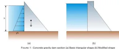
Basic layout
The basic shape of a concrete gravity dam is triangular in section (Figure 1a), with the top crest often widened to provide a roadway (Figure 1b).
FIGURE 1: Concrete gravity dam section (a)Basic triangular shape(b)Modified shape
water (9810 N/m³), W is the weight of the dam body. The top portion of the dam (Figure 1b) is widened to provide space for vehicle movement. A gravity dam should also have an appropriate spillway for releasing excess flood water of the river during monsoon months. This section looks slightly different from the other non-overflowing sections. A typical section of a spillway is shown in Figure 2.
Water pressure on dam
The pressure due to water in the reservoir and that of the tail water acting on vertical planes on the upstream and downstream side of the dam respectively may be calculated by the law of hydrostatics. Thus, the pressure at any depth h is given by γh kN/m² acting normal to the surface. When the dam has a sloping upstream face, the water pressure can be resolved into its horizontal and vertical components, the vertical component being given by the weight of the water prism on the upstream face and acts vertically downward through the centre of gravity of the water area supported on the dam face.
In spillway section, when the gates are closed, the water pressure can be worked out in the same manner as for non–overflow sections except for vertical load of water on the dam itself. During overflow, the top portion of the pressure triangle gets truncated and a trapezium of pressure acts below fig
FIGURE 23: Horizontal water force on spillway block during flood water over flow
The pressure due to tail water is obtained in a similar manner as for the upstream reservoir water.
In case of low overflow dams, the dynamic effect of the velocity of approach may be significant and deserve consideration.
4.11
ANALYSISSTRESS ANALYSIS a.General.
b.A stress analysis of gravity dams is performed to determine the magnitude and distribution of stresses throughout the structure for static and dynamic load conditions and to investigate the structural adequacy of the substructure and foundation.
c.Gravity dam stresses are analyzed by either approximate simplified methods or the finite element method depending on the refinement required for the particular level of design and the type and configuration of the dam. For preliminary designs, simplified methods using cantilever beam models for two-dimensional analysis or the trial load twist method for three-dimensional analysis are appropriate as described in the US Bureau of Reclamation (USBR), “Design of Gravity Dams” (1976).The finite element method is ordinarily used for the feature and final design stages if a more exact stress investigation is required.
d.Finite element analysis.
generally appropriate for concrete gravity dams. The designer should be aware that actual structure response is three dimensions a land should review the analytical and realistic results to assure that the two-dimension approximation is acceptable and realistic. For long conventional concrete dams with transverse contraction joints and without keyed joints, a two-dimensional analysis should be reasonably correct. Structures located in narrow valleys between steep abutments and dams with varying rock module which vary across the valley are conditions that necessitate three-dimensional modelling.
Measurement of Water Level on Upstream and Downstream Side
This measurement is useful for calculating the water pressure on the upstream face and downstream face of the dam.
A typical set of piezometer installations for an embankment dam is shown in Figure
FIGURE 31: Typical installation of piezometers in embankment dams
DESIGN PROCEDURE
design gravity dam
Loads on concrete dams
Loads can be classified in terms of applicability/relative importance as primary
loads, secondary loads, and exceptional loads.
Primary Loads: are identified as those of major importance to all dams, irrespective of type,
e.g. water and related seepage loads, and self-weight loads.
Secondary Loads: are universally applicable although of lesser magnitude (e.g. sediment load) or, alternatively, are of major importance only to certain types of
dams (e.g. thermal effectswithin concrete dams).
Exceptional Loads: are so designed on the basis of limited general applicability or having a low
probability of occurrence
(e.g. tectonic effects, or the inertia loads associated with seismic activity).
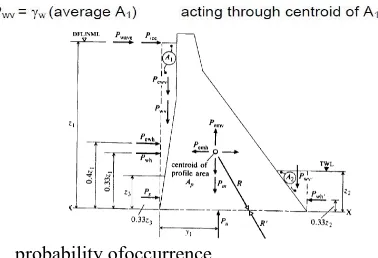
loading diagram on gravity dams
Primary Loads Water Load
Hydrostatic distribution of pressure with horizontal resultant force P
1
Vertical component of load will also exist in the case of an upstream face batter
Hydrostatic distribution of pressure with horizontal resultant force P
1
Seepage loads/uplift
The uplift is supposed to act on the whole width of
the foundation
FIGURE:32 Uplift pressure distribution for perfectly tight cutoff wall
Uplift pressure distribution for perfectly tight cutoff wall
Secondary loads
Sediment Load
The gradual accumulation of significant
deposits of fine sediment, notably silt, against
the face of the dam generates a resultant horizontal force, P
s.
Hydrodynamic wave
The upper portions of dams are subject to the impact of waves, P
wave.
The dimensions and force of waves depend on the extent of water surface, the velocity of wind, and other factors
6.4 Input data for analysis
Figure.5 MODEL STRUCTURE
Figure.6. STRUCTURE WITH DIMENSION
Figure.7. STRUCTURE WITH 3D VIEW
Figure.8. STRUCTURE WITH
Page | 1253 RESULTS & GRAPHS
1. Result Of Plate Principal Stresses LOAD
CASE
MAXIMUM MINIMUM
Seis mic Gravi ty Seis mic Gra vity DEAD LOAD
1.434 1.4 34
-0.17 -0.17
LOAD COMBIN ATION 1
15.9 15. 9
-2.4 -2.4
LOAD COMBIN ATION 2
67.39 48 -8.33 -5
EQX 0.54 - -0.07 -
EQY 0.15 -
-0.05 9
-
Reactions for Seismic Analysis
No de
X Y Z Mx M
y M z
6 8.62
7 -337
48 791 11.
5 20 9
12 32 356 53 600 15.
6 6
5 238.
9
338 128.
1
936 60
5 28 9
11 204.
2 326. 3 123. 5 919. 8 59 5 3.3 9
Reactions for Gravity Analysis
No de
X Y Z Mx M
y
Mz
6 719.
783 524 2.9 84 .9 652 3.7 21 0 1122 3.4
12 537.
59 397 6 31 7 112 3
56 5623
5 1125
.4 196 9 31 7 545 .8 90. 2 1024 8
11 943 290
9 84 .7 493 .04 43 5.8 184. 5 Displacements
Node Seismic Gravity
X (mm) Z (mm) X (mm) Z (mm)
2 295 185 197 123
1 88 153 58 102
13 1.5 16 1.5 12
16 527 274 351 351
CONCLUSION
STAADPRO gives an extremely adaptable figuring condition to learn or explore displaying suspicions and computational procedures identified with the static and seismic basic soundness of gravity dams in light of the gravity technique. It has been appeared in this paper a few suspicions identified with load conditions, splitting criteria, elevate weights powers and examination method could be utilized for static, seismic, and post-seismic security appraisals when all is said in done, the calculations are mind boggling to perform because of the coupling between the inspire weight and break length. In a genuine circumstance, parametric examinations are regularly performed to cover instabilities in quality and stacking parameters to take proper choice concerning a specific structure.
P a g e | 1255 1M.Tech, Student, Civil Engineering
Kakinada Institute Of Engineering And Technology. Yanam Road,, Matlapalem, Andhra Pradesh
2Assistant Professor, Civil Engineering, Kakinada Institute Of Engineering And Technology. Yanam Road,, Matlapalem, Andhra Pradesh
[1]. Adedeji, A. A. (2004); Finite Element Method, CVE 567 Lecture Notes, Department of Civil ngineering, University of Ilorin, Ilorin.
[2]. Bathe, K. J. (1996); Finite Element Procedures, Seventh Edition, PrenticeHall Inc, New Jersey.
[3]. CIWAT ENGINEERS (1996); Design Report of the University of Ilorin Dam, CIWAT ENGINEERS, Ilorin, pp 14 – 25.
[4]. EM 111022200 (1995); Design of Concrete Gravity Dams, Engineer Manual of the US Army Corps of Engineers, US Army Corps Publications Depot, National Technical Information Service, Springfield, VA, www.us.armycorps.engineers.com/engi neer’s manual.
[5]. Fenves, G. L. and VargasLoli, M. (1988); NonLinear Analysis of FluidStructure Systems, Journal Of Engineering Mechanics Division, ASCE Vol. 114, pp 219 – 240.
[6]. Hatami, K. (2001); Seismic Analysis of Concrete Dams, National Defence, Royal Military College of Canada, www.zworks.com/seismic
analysis/concrete dams/ Seismic Analysis of Concrete Dams.
[7]. Iroko, A. O. (2001); Hysterical Analysis of Strawbale as an Infill Material Subjected to Seismic Loadings (Vibration), B. Eng. Project, Submitted to the Dept. of Civil Engineering, University of Ilorin, Ilorin.
[8]. Lotfi, V. (2001); Seismic Analysis of Concrete Gravity Dams using Decoupled Modal Approach in Time Domain, Electronic Journal Of Structural Engineering, Vol. 3, www.ejse.org, pp 102 – 116.
[9]. Major, A. (1980); Dynamics in Civil Engineering, Vol. I IV, Second Edition, Collet’sHoldings Ltd, London.
[10]. Polyakov, S. V. (1985); Design of EarthquakeResistant Structures, Second Edition, MirPublishers.