• No results found

A Multiband Slot Antenna for GPS/WiMAX/WLAN Systems

N/A
N/A
Protected

Academic year: 2020

Share "A Multiband Slot Antenna for GPS/WiMAX/WLAN Systems"

Copied!
7
0
0

Loading.... (view fulltext now)

Full text

(1)

A Multiband Slot Antenna for

GPS/WiMAX/WLAN Systems

G.Punitha, B.Saranya, V.Swathi, Dr.D.Mohanageetha

UG Student, Dept. of ECE, S.A. Engineering College, Chennai, Tamilnadu, India

UG Student, Dept. of ECE, S.A. Engineering College, Chennai, Tamilnadu, India

UG Student, Dept. of ECE, S.A. Engineering College, Chennai, Tamilnadu, India

Professor, Dept. of ECE, S.A. Engineering College, Chennai, Tamilnadu, India

ABSTRACT: The design of multiband slot antenna includes various services such as LTE, GSM, PCS, GPS, WLAN and WiMAX bands. Each approach offers different advantages, depending on the required application. The introduction of a ground slot in a finite antenna ground plane can be further extended to include reconfigurable features. Now in this slot multiband planner system is proposed to intend as in GPS, WLAN(over two frequency band spectrum),and WiMAX. the design of four band slot antenna for the global positioning system, worldwide interoperability for microwave access and wireless local area network presented. The antenna consists of a rectangular with a T-Shaped feed patch, an inverted T-shaped stub and two E-shaped stub to generate four frequency bands. The aim of this project is to model and simulate a multiband slot antenna for various frequency bands. The dimensions of multiband slot antenna are calculated using transmission line model. The layout of the antenna is simulated in momentum an EM tool of High Frequency simulation Software(HFSS).

KEYWORDS: Multiband antenna, slot antenna, GPS, WiMAX, WLAN.

I.INTRODUCTION

In each and every case, the transmitters and receivers involved require antennas, even if some are hidden like inside laptop compuers equipped with Wi-Fi,or inside ratio. According to tha IEEE standards definitions of terms for antennas, antenna is basically defined as the means of transmitting and receiving radio waves. Antennas are required by any radio receiver or transmitter to couple its electrical connection to the electromagnetic field. Radio waves are electromagnetic waves which carry signals through the air or through space, at the speed of light. Radio transmitters and receivers are used to convey the signals or information in the systems including broadcast ratio, Wi-Fi point to point communications links and many remote controlled devices.

Types of antennas: Antennas are classified into many types which are the described below. On the basis of radiation.

Omni-directional antenna: Also called as weakly directional antennas which radiate and receive more or less in all directions.

Directional antenna: Also called as beam antennas which radiate and receive in a particular direction. A directional antenna is intended to maximize its coupling to the electromagnetic field in the direction of the other station or to cover a particular sector.

On the basis of the aperture:

Wire antenna: These types of antennas are familiar to layman as these antennas are seen everywhere like on automobiles, buildings, ships, aircrafts etc.

(2)

Micro strip Antennas: These antennas have use in space applications, government and commercial applications. They cosists of metallic patch on grounded substrate. These antennas are mounted on the surface of high performance aircraft, spacecraft, satellite, missiles.

On the basis of polarizations:

Linearly polarized antenna: If the antenna is transmitting or receiving in the vertical E direction then it is called vertically polarized antenna. If the antenna is transmitting or receiving in the horizontal E direction, then it is called horizontally polarized antenna.

Circularly polarized antenna: If the antenna is able to transmit or receive E field vectors of any orientations, then antenna is said to be circularly polarized antenna.

Antenna parameters

Return loss: It is a parameter which indicates the amount of power that is lost to the load ad does not return as a reflections. Hence the RL is a parameter to indicates how well the matching between the transmitter and antenna has taken place. Simply put it is S11 of an antenna. A graph of S11 of an antenna frequency is called its return loss curve. For

optimum working such a graph must show a dip at the operating frequency and have a minimum dB value at this frequency.

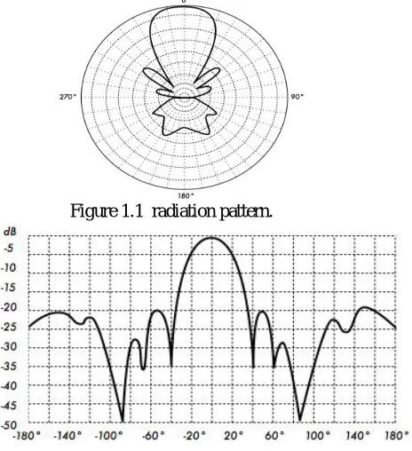
Radiation pattern: The Radiation pattern of an antenna is plot of tha far-field radiations properties of an antenna as a function of the spatial co-ordinates which are specified by the elevation angle (Ө) and the azimuth angle. It can be plotted as a 3D graph or as a 2D polar or Cartesian slice of this 3D graph. It is an extremely parameter as it shows the antenna directivity as well as gain at various points in space.

Figure 1.1 radiation pattern.

Figure 1.2 cartesian diagram

(3)

Figure 1.3 beam width

Polarisation, Polarisation is defined as the orientation of the electric field of an electromagnetic waves. Polarization is in general described by an ellipse. Two special cases of elliptical polarization are linear polarization and circular polarization. The initial polarisation of a radio wave is determined by the antenna. With linear polarization the electric field vector says in the same plane all the time. Vertically polarized radiation is somewhat less affected by reflections over the transmission path. Omni directional antennas are always have vertical polarizations. With horizontal polarizations, such reflections cause variations in received signal strength. Horizontal antennas are less likely to pick up man-made interference, which ordinarily is vertically polarized.

II. MICRO STRIP SLOT ANTENNA

Micro strip antennas can be divided into two basic types by structure, namely micro strip patch antenna and micro strip slot antenna. The slot antennas can be feed by micro strip line, slot line and CPW. Micro strip slot antenna is very simple in structure it consists of micro strip feed that couples electromagnetic waves through the slot above and slot radiates them. A micro strip-fed slot antenna offers a better isolation between the feed and the materials under measurement compared to the micro strip-fed micro strip antenna. They are more flexible in integration with other active and passive devices in a hybrid MIC and MMIC design. Furthermore, they are capable of producing omni-directional radiation pattern by the simply inserting quarter-wave thick foam and reflector. To improve the antenna performance by improving the coupling between the patch and feed line, different size and shapes of slots are experimented. H-shaped, bowtie, dog bone shaped slots had been studied. All these slot shapes provide better input impedance compared to a rectangular slot.

Figure 2.1 Micro strip slot antenna structure

Advantages

• They are very low profile, and can be fabricated using printed circuit techniques. • Light weight and low volume.

(4)

• Supports both, linear as well as circular polarization.

• Can be easily integrated with microwave and mill meter wave integrated circuits. • Capable of dual and triple frequency operation.

• Mechanically robust when mounted on rigid surfaces. Disadvantages

• Narrow bandwidth. • Low efficieny. • Low gain.

• Extraneous radiation from feeds and junctions. • Poor end fire radiator except tapered slot antennas. • Low power handling capacity.

• Surface wave excitation. Application

• Aerospace vehicles including high performance aircraft,space craft,satellites and missiles. • Mobile radios,phones and pagers.

• Base stations for personal communication. • Large ground based phased array antennas.

III.Proposed antenna design

Figure 3.1 antenna design

Figure 3.1 shows the antenna designed in with two E-stubs to support the radiation in the corner of the antenna and with a micro strip feed in the HFSS software. Initially the substrate is placed in XY plane and ground is placed parallel to it.

Figure 3.2 Return loss plot for 4 bands

1.00 2.00 3.00 4.00 5.00 6.00 7.00

Freq [GHz] -22.50 -20.00 -17.50 -15.00 -12.50 -10.00 -7.50 -5.00 -2.50 0.00 d B (S (1 ,1 )) HFSSDesign1

XY Plot 2 ANSOFT

Curve Inf o

(5)

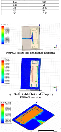
Table 3.1Return loss for different frequencies

FREQUENCY(GHZ) RETURN LOSS(dB)

1.57 -13.5

2.45 -20

3.5 -13.50

4.5 -10

5.2 -15.50

Electric field distribution

Figure 3.3 Electric field distribution of the antenna

Figure 3.4 E- Field distribution in the frequency range 2.56-3.23 GHZ

(6)

Figure 3.6 E-field distribution in the frequency range of 4.99-5.48GHZ

Antenna gain

Table 4.2 Comparison of antenna Gain at different Frequencies

Frequencies(GHz) Gain of the Existing Antenna(dB)

Gain of the Proposed Antenna(dB)

1.57 -6 3.55

2.45 2.33 3.93

3.5 3.14 5.02

5.2 2.92 4.86

IV.CONCLUSION

The design of planner four-bands slot antenna for GPS/WiMAX/WLAN has been presented. The antenna consists of a radiating slot loaded with a T-shaped feed patch, an inverted T-shaped stub and two E-shaped stubs. Simulation and measurement have been used to study the performance, in terms of return loss, radiation loss, realized peak gain and efficiency, of the antenna. Result have shown that the antenna has four frequency bands at about 1.575, 2.45, 3.5 and 5.2 GHZ which can be used to cover the GPS, WLAN, and WiMAX systems. Result of studied have also been used to propose a methodology of using the design for other frequency bands.

REFERENCES

[1] X. L. Sun, S. W. Cheung, and T. I. Yuk, “Dual-band monopole antenna with frequency tuneable feature for WiMAX applications,” IEEE Antennas Wireless Propag. Lett., vol. 12, pp.100-103, Dec. 2013.

[2] C. H. Chang and K. L. Wong, “Printed λ/8-PIFA for penta-band WWAN operation in the mobile phone,” IEEE Trans. Antennas Propag., vol. 57,no. 5, pp. 1373 - 1381, May. 2009.

[3] Y. D. Dong, H. Toyao, and T. Itoh, “Design and characterization of miniaturized patch antennas loaded with complementary split-ring resonators,” IEEE Trans. Antennas Propag., vol. 60, no. 2, pp. 772-785,Feb. 2012.

[4] S. W. Su, “High-gain dual-loop antennas for MIMO access points in the2.4/5.2/5.8 GHz bands,” IEEE Trans. Antennas Propag., vol. 58, no. 7, pp. 2412-2419, Jul. 2010.

[5] K. L. Wong, and L. C. Lee, “Multiband printed monopole slot antenna for WWAN operation in the laptop computer,” IEEE Trans. Antennas Propag., vol. 57, no. 2, pp. 324-330, Feb. 2009.

[6] Y. Cao, B. Yuan, and G. F. Wang, “A compact multiband open-ended slot antenna for mobile handsets,” IEEE Antennas Wireless Propag. Lett., vol.10, pp. 911-914, 2011

(7)

[8] M. J. Chiang, S. Wang, and C. C. Hsu, “Compact multifrequency slot antenna design incorporating embedded arc-strip,”IEEE Antennas Wireless Propag. Lett., vol. 11, pp. 834-837, 2012.

[9] A. P. Saghati, M. Azarmanesh, and R. Zaker, “A novel switchable single and multifrequency triple-slot antenna for 2.4-GHz bluetooth, 3.5-GHz WiMax, and 5.8-GHz WLAN,” IEEE Antennas Wireless Propag. Lett., vol. 9, pp. 534-537, 2010.

[10] J. H. Lu and B. J. Huang, “Planar compact slot antenna with multi-band operation for IEEE 802.16m application,” IEEE Trans. Antennas Propag., vol. 61, no. 3, pp. 1411-1414, Mar. 2013

[11] L. Dang, Z. Y. Lei, Y. J. Xie, G. L. Ning, and J. Fan, “A compact microstrip slot triple-band antenna for WLAN/WiMAX applications,” IEEE Antennas Wireless Propag. Lett., vol. 9, pp. 1178-1181, 2010.

[12] W. Hu, Y. Z. Yin, P. Fei, and X. Yang, “Compact triband square-slot antenna with symmetrical L-Strips for WLAN/WiMAX applications,” IEEE Antennas Wireless Propag. Lett., vol. 10, pp. 462-465, 2011.

[13] M. Bod, H. R. Hassani, and M. M. Samadi Taheri, “Compact UWB printed slot antenna with extra bluetooth, GSM, and GPS bands,” IEEE Antennas Wireless Propag. Lett., vol. 11, pp. 531-534, 2012.

[14] L. Liu, Y.F. Weng, S. W. Cheung, T. I. Yuk and L. J. Foged, “Modelingof cable for measurements of small monopole antennas,” Lough borough Antennas & Propagation Conference, 14-15 November 2011,Loughborough, (LAPC 2011), UK.

[15] L. Liu, S. W. Cheung, Y. F. Weng and T. I. Yuk, “Cable effects on measuring small planar UWB monopole antennas” in “Ultra Wideband”,Edited by Mohammad Matin, Intech, ISBN 978-953-51-0781-1, October 2012.

[16] X. L. Sun, S. W. Cheung and T. I. Yuk, “Dual-band monopole antenna with compact radiator for 2.4/3.5 GHz WiMAX applications”, Microw. Opt. Tech. Lett., vol. 55, no. 8, pp. 1765–1770, Aug. 2013.

[17]C.A. Balanis, “Antenna theory - analysis and design” John Wiley & Sons,(3rd Edition), 2005.

[18] C. C. Chen, C. Y. D. Sim and F. S. Chen, “A Novel Compact Quad-Band Narrow Strip-Loaded Printed Monopole Antenna,” IEEE Antennas Wireless Prop. Letters,vol. 8, pp. 974 – 976, Aug. 2009.

[19] R. A. Bhatti, Y. T. Im and S. O. Park, “Compact PIFA for Mobile Terminals Supporting Multiple Cellular and Non-Cellular Standards,” IEEE Trans. Antennas Prop,vol. 57, no. 9, pp. 2534 – 2540, Sep. 2009.

[20] Y. Cao, B. Yuan, G. Wang,“ A Compact Multiband Open-Ended Slot Antenna for Mobile Handsets,” IEEE Antennas Wireless Prop. Letters, vol. 10, pp. 911 – 914, Sep. 2011.

[21]S. I. Latif and L. Shafai, “Investigation on the EM-Coupled Stacked Square Ring Antennas With Ultra-Thin Spacing,” IEEE Trans. Antennas Prop, vol. 59, no. 11, pp. 3978 – 3990, Nov. 2011.

[22]K. Huang and T. Chiu, “Triband Inverted-F Antenna With Stacked Branched Monopoles and a Parasitic Strip,” IEEE Antennas Wireless Prop. Letters, vol. 10, pp. 1208 – 1211, Nov. 2011.

[23]O. P. Falade, M. U. Rehman, Y. Guo, X. Chen and C. G. Parini, “Single Feed Stacked Patch Circular Polarized Antenna for Triple Band GPS Receivers,” IEEE Trans. Antennas Prop, vol. 60, no. 10, pp. 4479 – 4484, Oct. 2012.

[24]F. J. H. Martinez, G. Zamora, F. Paredes, F. Martin and J. Bonache, “Multiband Printed Monopole Antennas Loaded With OCSRRs for PANs and WLANs,” IEEE Antennas Wireless Prop. Letters, vol. 10, pp.1528 – 1531, Dec. 2011.

Figure

Figure 1.2 cartesian diagram
Figure 1.3 beam width
Figure 3.2 Return loss plot for 4 bands  Freq [GHz]
Figure 3.3 Electric field distribution of the antenna
+2

References

Related documents

Figure 2-10: Experimental displacement, velocity, strain, and strain rate for an AA5182-O specimen formed with 7.5kV in free forming.. Image from Rohatgi

Sg-2, Hornblende in clinopyroxene bearing hornblende gabbroic inclusion from Shigarami, Nagano Prefecture, Central Japan (Yamazaki, et al, 1966 ). Kj-1, Hornblende in

The performance of a text classification model is heavily dependent upon the type of words used in the corpus and type of features created for classification.Text

Even when the average is calculated to include nontufted as well as tufted offspring (last column, table 5), the degree of tuftedness is higher than that of either parent in

(A) Misexpression of CHE-1 and F1 RNAi against the histone chaperone gene lin-53 (Caf1p48/RBBP4/7) on solid worm growth media allows germ cell conversion (GeCo) to ASE neuron-like

NATPAC, based on detailed assessment of large sized buses operating from Thiruvananthapuram city, has conducted a scientific study and presented alternative design options for

The optimum size of solar thermal storage for space heating system depends on the type of application, and is a function of several parameters, such as type of material,

Half of the germ cells from the haplo-IV region of such a mosaic will be functioning nullo-IV germ cells, and when these meet normal haploid germ cells, the result will