International Journal of Research (IJR) Vol-1, Issue-10 November 2014 ISSN 2348-6848
Vijayakrishna Satyamsetti
A Research In AC-AC/DC-DC DAB Based Solid State Transformers
P a g e
|
519A Research In
AC-AC/DC-DC DAB
Based
Solid State Transformers
Vijayakrishna Satyamsetti
Department of Power Electronics and Power Systems, School of Electrical Engineering, Jawaharlal Nehru Technological University Kakinada, Kakinada , India
ABSTRACT:
This dissertation gives the investigation in the area of AC/AC power conversion and DC/DC with solid state transformer. The
proposed single phase solid state
transformer with bidirectional flow
capability may find application in compact isolated PWM AC drives. This topology along with the proposed control has the following advantages. A)input power factor correction b) Common mode voltage suppression at the load end , c) high quality output voltage waveform (compared to the conventional space vector PWM) and d)minimizing output voltage losses, And lossless commutation for soft switching .
KEYWORDS: Solid State Transformer, Bridge converters, Fly back converters, DAB converter Module
INTRODUCTION:
Replacement of a line frequency transformer with a high frequency transformer results in the considerable reduction in size and cost. With the advancement of power semiconductor devices it is possible to apply high frequency PWM converter as distribution transformers[1], and the
development of high voltage and high current devices capable of switching at a high frequency and have a relatively low conduction loss [2]. These development have enabled the possible realization of HFT link AC/AC power converters known as power electronic converters (PET) or solid state transformers (SST). SSTs can be employed in modern power distribution systems due to advanced features like voltage and frequency control, reactive power support etc. Another major area of application is high power density electric motor drives for example in Electric Traction [3] [4[5], Wind Power [6] [7].
Extensive classification of different types of SSTs found in [8].Two stage SSTs (AC-DC-AC) are of two kinds: high voltage DC link (HVDC) [9] and low voltage DC link (LVDC) [3] [4] [5].
SST TOPOLOGIES :
International Journal of Research (IJR) Vol-1, Issue-10 November 2014 ISSN 2348-6848
Vijayakrishna Satyamsetti
A Research In AC-AC/DC-DC DAB Based Solid State Transformers
P a g e
|
520number of topologies proposed for SST as well as for general AC-AC power
conversion have been surveyed there in.
An approach to classify the SST topologies and select the appropriate configuration according to the specific needs was introduced.
In this classification, as seen in Fig.1 four SST configurations that cover all the possible SST topologies are identified: a)single stage with no DC link, b)two-stage with low voltage DC (lvdc) link, c) two – stage with high voltage DC (HVDC) link, and d)three-stage with both HVDC AND LVDC links. The DC link of the third configuration is not appropriate for DES and DER integration since it is high voltage and no isolation from the grid : therefore, topologies under that classification are not practical for SST implementation.
Fig.1. SST configurations: (a) single-stage, (b) two-stage with LVDC link (c) two-stage
with HVDC link, and (d) three-stage.
Presently, Insulated Gate Bipolar Transistors (IGBT) and HF transformers with distribution voltage ratings are not readily available. In order to solve this problem, a modular approach can be used to meet this requirement in which the high voltage AC (HVAC) sides of several modules are series connected[10]. Additionally by using the interleaving approach, the ripple currents may be reduced which translated into smaller filter size. Fig.2 shows a fully modular single-stage configuration a modular two-single-stage configuration is shown in Fig.3 where only AC-AC stage is modular. Fig.4 shows a modular three stage configuration.
Fig.2 modular single-stage SST
International Journal of Research (IJR) Vol-1, Issue-10 November 2014 ISSN 2348-6848
Vijayakrishna Satyamsetti
A Research In AC-AC/DC-DC DAB Based Solid State Transformers
P a g e
|
521Fig.4 modular three-stage SST
Six representative SST topologies have been identified in [11].
a) A single-stage SST comprising AC-AC Full-bridge converter modules. b) A single-stage SST comprising
AC-AC Fly back converter modules. c) A two-stage SST comprising AC-DC
isolated boost converter modules and a pulse with modulated PWM dual-phase inverter.
d) A two-stage SST comprising AC-DC dual active bridge (DAB) converter modules and a PWM dual-phase inverter.
e) A three-stage SST comprising a cascaded-full-bridge rectifier, DC-DC DAB modules and a PWM dual-phase inverter.
f) A three-stage SST comprising a diode-clamped multilevel rectifier, DC-DC full-bridge converters and a PWM dual-phase inverter.
The single-stage SST topologies require simple control. Their main drawback is the lack of capabilities that the presence of a DC link offers, e.g. Input Power Factor correction. Fig.5 and Fig.6 show the AC-AC Full bridge SST and the AC-AC Fly back based SST, respectively. For simplicity, both
SST topologies are implemented with a single AC-AC module. The two-stage SST topologies offer a LVDC link for DER and DES integration. However, due to their lack of HVDC link, the LVDC link voltage may have a larger 120Hz ripple, caused by the 120Hz ripple currents generated by both AC sides
Fig.5 Single-stage SST based on an AC- AC Full-bridge converter.
Fig.6 Single-stage SST based on AC-AC Fly back converter.
International Journal of Research (IJR) Vol-1, Issue-10 November 2014 ISSN 2348-6848
Vijayakrishna Satyamsetti
A Research In AC-AC/DC-DC DAB Based Solid State Transformers
P a g e
|
522desirable for an SST. The main drawback of this SST topology is large number of components which translates into possibly lower efficiency and reliability.
Fig.7 Two-stage SST based on an AC-DC Isolated Boost converter
Fig.8 Two-stage SST based on an AC-DC DAB
Fig.9. Modular three-stage SST based on a Four-level Rectifier and three DC-DC DAB
converters
Fig.9 and Fig.10 shows the fully modular versions of DC-DC DAB based SST and the DC-DC Full-bridge SST, respectively.
Fig.10. Modular three-stage SST based on a Four-level Rectifier and three DC-DC
Full-bridge converters.
International Journal of Research (IJR) Vol-1, Issue-10 November 2014 ISSN 2348-6848
Vijayakrishna Satyamsetti
A Research In AC-AC/DC-DC DAB Based Solid State Transformers
P a g e
|
523Fig.11. Functional capabilities supported by the SST topologies
LOSSLESS COMMUTATION :
Commutation refers to the change in the direction of the current in each of the primary windings and transfer of the current from one half of the secondary winding to the other half when the modulation is changing from one state to another. Transformer windings have leakage inductances. In Fig ,L1 refers to the primary
leakage inductance.L21 and L22 represent the leakage inductances present in the upper and lower half of the secondary winding respectively.
In order to change the current through these leakage inductances a proper voltage needs to be applied Hereto he input converter is switched to provide the required voltage from the input ac source. Note that
at any instant of time, at least 0.5 times the peak of the input line to neutral voltage is available (in both directions: positive or negative), to be applied across the transformer primary winding of any phase.
International Journal of Research (IJR) Vol-1, Issue-10 November 2014 ISSN 2348-6848
Vijayakrishna Satyamsetti
A Research In AC-AC/DC-DC DAB Based Solid State Transformers
P a g e
|
524to upper state and the load current is negative. Since the commutation period is much smaller than the time period ( To =2π/ωo) of the output load current, the load is modeled as a dc current source.
Fig.12. Power transfer through lower half of the secondary winding
Fig.12. NP1 is high
Fig.13.NP2 is high
Fig.14.NP2 is high
International Journal of Research (IJR) Vol-1, Issue-10 November 2014 ISSN 2348-6848
Vijayakrishna Satyamsetti
A Research In AC-AC/DC-DC DAB Based Solid State Transformers
P a g e
|
525Fig. 12 shows power transfer to the load through the lower half of the secondary winding. Switch Q4and diodeD3are conducting. Switch Q is open during the power transfer mode. The commutation is done on a phase-by-phase basis. A proper voltage needs to be applied to the primary of each phase that is independent of other phases. This is the reason why switch Q is turned ON during commutation. Commutation starts when signal NP1 goes high .The first stage of NP1 is referred to as NP1ain the Tables I and II. At this stage, switch Q3is turned OFF and Q is turned ON. This particular commutation requires a negative voltage to be applied transformer primary. Say that at this instant of time v
Cn is most negative input voltage. So the switch S cris turned ON. During the second stage of NP1 (NP1b), switch Q2isturned ON. This forward biases the diode D1(Fig. 13)and current i21starts building in the upper half of the primary winding. The equivalent circuit of this stage is given in Fig. 16.
Fig.16 equivalent circuit during commutation
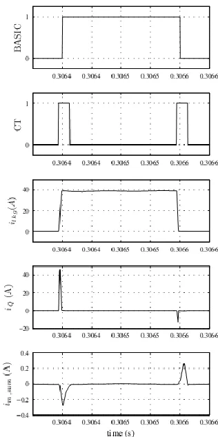
And Fig.17, 18 shows the output waveforms for commutation process.
Fig.17Output Waveforms for Commutation
International Journal of Research (IJR) Vol-1, Issue-10 November 2014 ISSN 2348-6848
Vijayakrishna Satyamsetti
A Research In AC-AC/DC-DC DAB Based Solid State Transformers
P a g e
|
526 CONCLUSION:In this work , a naval ac-ac and dc-dc dual active bridge converter is proposed for solid state transformer application. A high frequency transformer is used to minimize the bulk of passive components. Hence all possible topologies were discussed along with the inherent capability of output power factor and the input power factor is control and loss less commutation
for leakage inductances.
Compared to the state-of-the-art approach with LFT and three-phase PWM rectifiers, the AC/DC SST achieves 40% lower losses while also providing full galvanic isolation and the characteristic increased functionalities provided in general by AC/DC SST technology. As a consequence, unidirectional SST structures are a promising solution for supplying high-power DC loads directly from the MV AC grid.
REFERENCES:
[1]. E. Ronan, S. Sudhoff, S. Glover, and D. Galloway,“A powerelectronic based distribution transformer ,” IEEE Transactions on Power Delivery ,vol. 17, no. 2, pp. 537–543,( Apr 2002).
[2] M. Das, C. Capell, D. Grider, R. Raju, M. Schutten, J. Nasadoski,S. Leslie, J. Ostop, and A. Hefner,“10kv,120 a sic half h-bridgepower
mosfetmodulessuitableforhighfrequency,me diumvoltageapplications,”in Energy
Conversion Congress and Exposition (ECCE),(2011) IEEE, 2011, pp. 2689–2692. [3] M. Pittermann, P. Drabek, Z. Peroutka, and M. Cedl, “New configurationof traction converter with medium-frequency transformer
usingmatrixconverters,”Industrial
Electronics, IEEE Transactions on, vol.58,no.11, pp. 5041–5048, Nov. )2011). [4] M. Carpita, M. Marchesoni, M. Pellerin, and D. Moser, “Multilevelconverter for traction applications: Small-scale prototype tests results,”Industrial Electronics, IEEE Transactions on, vol. 55, no. 5, pp. 2203– 2212,( 2008).
[5] M. Glinka and R. Marquardt, “A new ac/ac multilevel converter family,”Industrial Electronics, IEEE Transactions on, vol. 52, no. 3, pp. 662–669, (2005).
[6] M. Molinas, A. Garces and “A study of efficiency in a reduced matrix converter for offshore wind farms, “Industrial Electronics, IEEE Transactions on, vol. 59, no. 1, pp. 184–193, (2012).
[7] R. Burgos, X. She, A. Huang, F. Wang, and “Wind energy system with integrated functions of active power transfer, reactive powercompensa-tion,and voltage conversion,” Industrial Electronics IEEE Transactions on, vol. PP, no. 99, p. 1, (2012).
International Journal of Research (IJR) Vol-1, Issue-10 November 2014 ISSN 2348-6848
Vijayakrishna Satyamsetti
A Research In AC-AC/DC-DC DAB Based Solid State Transformers
P a g e
|
527[9] S. Hosseini, M. Sabahi, M. Sharifian, A. Goharrizi, and G. Gharehpetian, “Zero-voltage switching bi-directional power electronic transformer, “Power Electronics, IET, vol. 3, no5,pp.
[10] T.Krishnamurthy, H.; Ayyanar, R.; , "Stability analysis of cascaded converters for