Fuzzy Based LED Lighting Control Using
Integrated Buck Buck Boost Converter
Shaharban K.E
1, Muhamed Noufal .C
2PG Student [PEPS], Dept. of EEE, Federal Institute of Science And Technology, Kerala, India1
Assistant professor, Dept. of EEE, Federal Institute of Science And Technology, Kerala, India2
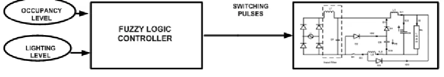
ABSTRACT: Power factor correction of high frequency switch mode power supply and its application in Fuzzy based LED Lighting control is presented in this paper. A high step-down transformer less single stage single-switch ac/dc converter is designed. The topology integrates a buck-type power-factor correction (PFC) cell with a buck boost dc/dc cell for output voltage regulation. It is a one-stage one-switch AC/DC converter which steps down the voltage without a transformer. It combines a buck type PFC cell with a buck-boost type DC/DC cell. Energy-saving opportunities of sunlight harvesting is utilised in this paper. Classic control systems, based on continuous dimming present some difficulties to adjust their performances to the rapid changes in sunlight. Taking these aspects into account, fuzzy controlled system is presented.
KEYWORDS: Power-factor Correction, Sunlight Harvesting, Fuzzy control.
I.INTRODUCTION
During the last three decades, the electricity consumption in indoor and outdoor lighting systems has continuously increased. For instance, nowadays 30% to 45% of a building's electricity bill is typically for lighting. That is why the implementation of sustainable energy development has addressed this sector as having an important potential regarding energy savings. Due to the increase of environmental concerns, lighting control systems will play an important role in the reduction of energy consumption of the lighting without impeding comfort goals. Energy is the single most important parameter to consider when assessing the impacts of technical systems on the environment. Energy related emissionsare responsible and central to the most serious global environmental impacts and hazards,including climate change, acid deposition, smog and particulates. Lighting is often one of the largest electrical load, but its energy saving potential is often neglected
.
To fulfill the requirements about comfort and energy efficiency, building managers have implemented programs to reduce lighting energy requirements by installing more efficient light sources and luminaries. However, this is not sufficient. Lighting energy management has to provide the optimal lighting level for the tasks being performed using the most efficient light source suitable for the application, and providing light only when and where it is needed. This can be achieved by using lighting control strategies and lighting control system. The main purpose of these systems is to reduce energy consumption while providing a productive visual environment.
ISSN (Print) : 2320 – 3765 ISSN (Online): 2278 – 8875
I
nternational
J
ournal of
A
dvanced
R
esearch in
E
lectrical,
E
lectronics and
I
nstrumentation
E
ngineering
(An ISO 3297: 2007 Certified Organization)
Vol. 4, Issue 11, November 2015
are satisfied. The first drawback of this approach is that it is subjective, with no feedback lux measurement information and thus inaccurate.
Within any building of today, the110/230Vac; 60/50 Hz ac power grid is the only power supply available to power both ac and dc electrical loads. An ac-dc power converter is employed to convert the existing 230Vac power source coming from the public utilities into a much lower voltage and safer dc power source to power these dc LED luminaries directly. Among existing ac-dc converters, most of them are comprised of a boost power factor correction (PFC) cell followed by a dc/dc cell for output voltage regulation . For application with low output voltage (e.g., 48V ), this high intermediate bus voltage increases components stresses on the dc/dc cell. Therefore, a high step-down transformer is usually employed even when galvanic isolation is not mandatory. Leakage inductance of the transformer causes high spike on the active switch and lower conversion efficiency. To protect the switch, snubber circuit is usually added resulting in more component counts.
High transformerless step down ac/dc converter [2] is suitable for low voltage applications. It is an integrated buck buck boost converter .The converter is able to achieve low intermediate bus and output voltages in the absence of transformer simple control structure with a single-switch; positive output voltage high conversion efficiency due to part of input power is processed once and input surge current protection because of series connection of input source and switch.
III.PROPOSED TOPOLOGY
The sustainable development concept has revived the interest for Sunlight harvestingas any day lit area has very promising energy-saving opportunities.However, sunlight is adynamic source of lighting. Apart the behaviour of human occupants, the lighting controls play a key role inthis action. Lighting controls provide building operators with the means to manage theway lighting energy is used in buildings more efficiently. These systems use various control strategies to (1) reduce wasted hours of lighting in unoccupied spaces, (2) automatically adjust electric light levels in synchrony with available daylight or age-related changes in luminaire output. Unfortunately, daylightis a dynamic source of lighting, i.e. the illuminance from the sky is not constant, and the variations in daylight can be quite large depending on season, location or latitude, and cloudiness. As a result, electric lighting control systems will be needed from time to time to adapt the lighting systems to changing lighting conditions. Classic control systems present some difficulties to adjust their performances to the rapid changes in daylight and to occupant’s preferences. Taking into account these aspects, fuzzy control could be a bettersolution.
Fig. 1 Proposed Topology
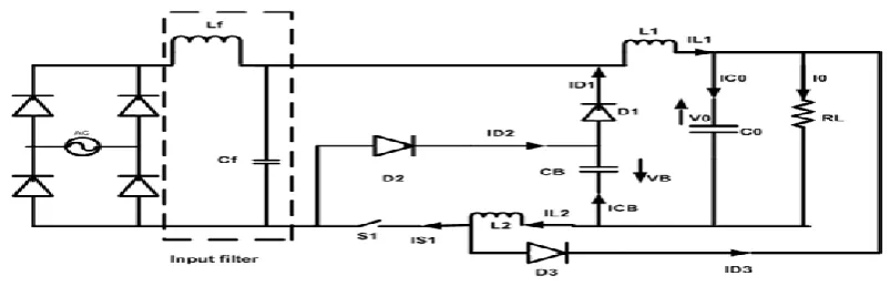
Fig. 2 Integrated buck-buck-boost converter.
Integrated Buck Buck Boost Converter
,
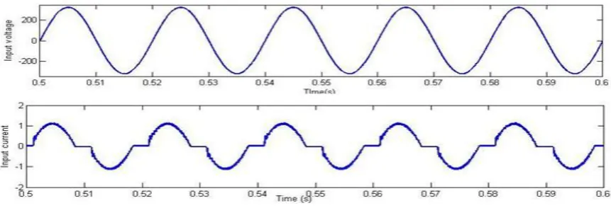
which integrates a buck based PFC (L1; S1;D1;C0 and CB) and buck boost dc/dc cell (L2; S1;D2;D3;C0 and CB) is illustrated in Fig.2. Moreover,both cells are operated in discontinuous conduction mode (DCM) so there are no currents in both inductors L1 and L2 at the beginning of each switching cycle t0. Due to the characteristic of buck PFC cell, there are two operating modes in the circuit. Operation of converter is divided into two modes mode A and mode B. Modes are determined by comparing the instantaneous value of input voltage and sum of intermediate voltage and output voltage as shown in Fig 3. When the input voltage is smaller than the sum of intermediate bus voltage , and output voltage, the converter operates in mode A.Mode Boccurs when the input voltage is greater than the sum of the bus voltage and output voltage. The intermediate bus voltage of the circuit is able to keep below 150V at all conditions of input and output. Thus, the lower voltage rating of capacitor can be used. Moreover, the topology is able to obtain low output voltage without high step-down transformer. Owing to the absence of transformer, the demagnetizing circuit, the associated circuit dealing with leakage inductance, and the cost of the IBuBuBo converter are reduced.Fig. 3Input voltage and current waveform.
ISSN (Print) : 2320 – 3765 ISSN (Online): 2278 – 8875
I
nternational
J
ournal of
A
dvanced
R
esearch in
E
lectrical,
E
lectronics and
I
nstrumentation
E
ngineering
(An ISO 3297: 2007 Certified Organization)
Vol. 4, Issue 11, November 2015
Fig. 4 Proposed Cicuit
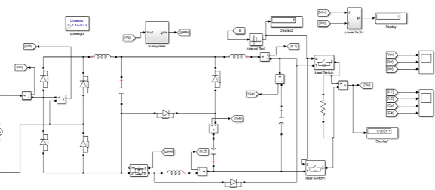
IV.SIMULINK MODEL AND SIMULATION RESULTS
Fig. 5 Simulink model of Proposed Configuration
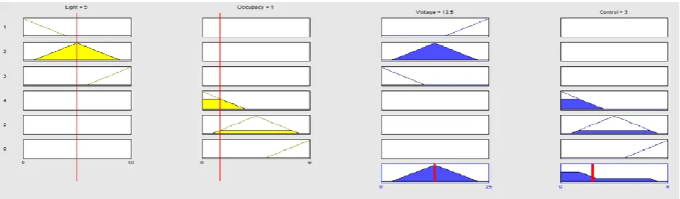
Fig. 6 Controller 1 rule view for zero occupancy
The simulation of the proposed circuit is done for various conditions of occupancy and lighting. Fig 6and Fig 7 shows the rule view of controller 1 for zero and non zero occupancy conditions respectively. For zero occupancy condition, the control signal is very low so that the load will be in off condition. For non zero occupancy condition, the control signal is high, so that the load will be in on condition. From the simulation results it is clear that as the light availability increases,the reference voltage decreases and vice versa. The second controller tries to attain the reference voltage.
Fig. 7 Controller 1 rule view for non zero occupancy
ISSN (Print) : 2320 – 3765 ISSN (Online): 2278 – 8875
I
nternational
J
ournal of
A
dvanced
R
esearch in
E
lectrical,
E
lectronics and
I
nstrumentation
E
ngineering
(An ISO 3297: 2007 Certified Organization)
Vol. 4, Issue 11, November 2015
Fig. 8Controller 2 rule view
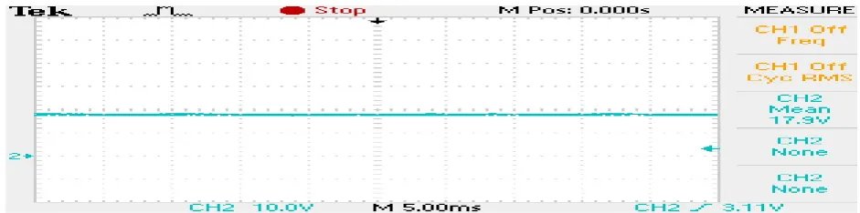
Fig 9 shows the input voltage and input current waveform of the converter. Fig 10 shows the output voltage waveform of the converter. The output voltage is maintained constant at 18V.
Fig. 9 Input voltage and current waveform
Fig. 10Output voltage waveform
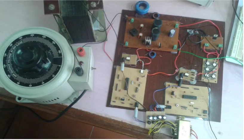
V.EXPERIMENTAL RESULTS
Power Supply
Integrated Buck Buck Boost Converter
MOSFET gate drives
dsPIC Controller unit for PWM generation
LED Lights
Fig. 11 Hardware Setup
ISSN (Print) : 2320 – 3765 ISSN (Online): 2278 – 8875
I
nternational
J
ournal of
A
dvanced
R
esearch in
E
lectrical,
E
lectronics and
I
nstrumentation
E
ngineering
(An ISO 3297: 2007 Certified Organization)
Vol. 4, Issue 11, November 2015
Fig. 13Input Voltage and Input Current
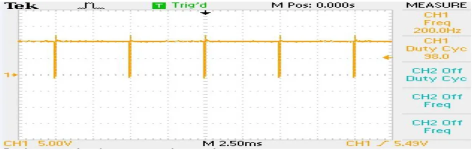
Fig. 14 Switching Pulse to Switch S1
Switch S1 is provided with 20kHz switching pulses by the controller 1. As the input voltage conditions vary the controller varies the duty ratio and maintains output voltage constant at 18V.
Fig. 15 Switching Pulse to Switch S2 at low light conditions
Fig. 16 Switching Pulse to Switch S2 at High light conditions
At High light conditions, controller 2 decreases the duty ratio of the S2 switching pulses accordingly so that light output of LED decreases. The low duty ratio switching pulses are shown in Fig. 15.
Fig. 17 Output Voltage
VI.CONCLUSION
Daylighting has a very promising energy-saving potential and became an attractive alternative to conventional indoor electric lighting systems. Classic control systems, based on continuous dimming, present some difficulties to adjust their performances to the rapid changes in daylight depending on season, location or latitude, and cloudiness. Taking into account these aspects, fuzzy control could be a better solution in implementation of day lighting, an issue that cannot be easily represented by mathematical modelling because datais unavailable, incomplete, or too complex.By controlling the intensity of LED lighting to reach the satisfactory level and in combination with the use of the day lighting, it is seen that the energy is used efficiently with the best effort for energy saving. The integrated buck-buck-boost converter (IBuBuBo) is able to achieve high power factor.
REFERENCES
[1] Yen Kheng Tan, Truc Phuong Huynh, and Zizhen Wang “ Smart Personal Sensor Network Control for Energy Saving in DC Grid Powered LED Lighting System ”IEEE Trans On Smart Grid, vol. 4, no. 2, pp. 669- 676, June 2013.
[2] Shu-Kong Ki, and Dylan Dah-Chuan Lu “ A High Step-Down Transformerless Single- Stage Single-Switch AC/DC Converter ”IEEE Trans on Power Electronics, vol. 28, no. 1,pp. 36- 45, January 2013.
[3] Q. Zhao, F. C. Lee, and F.-s. Tsai, “ Voltage and current stress reduction in single-stagepower-factor correction AC/DC converters with bulk capacitor voltage feedback ”IEEETrans. Power Electron., vol. 17, no. 4, pp. 477- 484, Jul. 2002.