Analysis of Distributed Generators with Fuzzy logic Controller
Based Inverter at un-balanced loads
Mr. K.N. RAJU Assistant Professor
Department of Electrical & Electronics Engineering, Lords Institute of Engineering and technology, Survey No. 32, Near Police Academy Junction, Himayathsagar,
Hyderabad-500008 (Dt); Telangana, India. Email:[email protected]
MUKARRAM ALI KHAN M-tech Scholar
Department of Electrical & Electronics Engineering, Lords Institute of Engineering and technology, Survey No.32, Near Police Academy Junction, Himayathsafar,
Hyderabad-500008 (Dt); Telangana, India. Email:[email protected]
Abstract-The design of a fuzzy logic controller using the voltage as feedback for significantly improving the dynamic performance of converter. Renewable energy resources (RES) are being increasingly connected in distribution systems utilizing power electronic converters. This paper presents a new control strategy for achieving maximum benefits from these grid-interfacing inverters using the closed loop P-I controller and fuzzy logic controller, when installed in 3-phase 4-wire distribution systems. The inverter is controlled to perform as a multi-function device by incorporating active power filter functionality. The inverter can thus be utilized as: 1) power converter to inject power generated from RES to the grid, and 2) shunt APF to compensate current unbalance, load current harmonics, load reactive power demand and load neutral current. All of these functions may be accomplished either individually or simultaneously. The THD and power factor variations for both PI-controller and fuzzy logic controller are also shown. This new control concept is demonstrated with extensive MATLAB/Simulink .Finally the proposed scheme is applied for both balanced, unbalanced linear and non linear loads. The proposed concept can be implemented to Fuzzy logic controller by using Matlab/Simulink software.
Key words-Distributed generation, 3-leg inverter, 4-leg inverter, unbalanced load.
I. introduction
In recent years, eco-friendly distributed
generation systems (DGS) such as wind turbines, solar cells, and fuel cells are dramatically growing because they can fulfill the increasing demand of electric power due to the rapid growth of the economy and strict environmental
regulations regarding greenhouse gas emissions.
Generally, the DGSs are interconnected in parallel with the electric utility grid and provide maximum electric power to the grid. However, there are some areas (e.g., remote islands or villages) where the connection to the grid is expensive or impractical and then small scaled standalone DGSs are the only efficient and economical options. In such DGSs, depending on consumers ‟power demand, there are situations where some DGSs operate in parallel or independently. In either case, a stable operation of each DGS unit is as important as the stability of the parallel operating DGSs in which the proper load sharing of each unit is one of main research issues since the voltage controller is commonly used in a single DGS unit or multipleDGS units. For this reason, the voltage
controller design for a single DGS unit, which can guarantee a good voltage regulation under unbalanced and nonlinear loads, is an interesting topic in the field of the DGSs control.
For the purpose of improving the quality of inverter output voltage, many researchers are working on designing the controllers for dc–ac power converters. In a robust controller is developed for balanced and unbalanced systems, which considers the uncertainties of the load parameters. However, nonlinear load is not fully addressed. In a repetitive control is used to regulate the UPS inverters. However, the slow response and lack of the systematic method to stabilize the error dynamics with the repetitive control are being the main problems. In an alternative control strategy with a feed forward compensation component can significantly mitigate the effect of load disturbance and make the controller design simple. Nevertheless, the application of this method is mainly limited to balanced load conditions. In a current control technique based on the spatial repetitive control is applied to a single-phase inverter and it also improves the performance of the current controller by estimating the disturbances. Although this control can obtain good results under nonlinear load, it may not guarantee a good voltage tracking capacity for a three-phase system. In a robust servomechanism voltage controller and a discrete-time sliding mode current controller are presented to control a single distributed generation unit in a standalone mode which can operate well under a sudden load change, an unbalanced load, and a nonlinear load.
Fig.1: 3-leg inverter with split DC link capacitor.
compensators are usually provided near the unbalanced load end. However with the advent of 4-leg inverters (see Fig.3), it is possible to handle unbalanced loads without affecting terminal voltages [6], [7]. The load neutral can be connected to the center of fourth leg and zero sequence currents flowing through neutral can be controlled.
Fig.2: 3-leg inverter interface with -Y transformer.
Fig.3: 4-leg inverter.
Advantages of 4-leg inverter interfaces are as follows:
There are no ripples in DC link voltage when
4-leginverters cater to unbalanced or nonlinear loads. So there is no need of large DC link capacitors as is the case of3-leg split DC link topology.
The 3-dimensional Space Vector Modulation
(3-D SVM) technique enhances the utilization of DC link voltage [8].
Presence of fourth neutral leg eliminates the requirement of bulky transformers for power evacuation (at least in small low voltage stand-alone DG systems).
The 4-leg inverters are widely used as active load compensators [9], [10]. The capability of using 4-leg inverter as an interface for stand-alone micro grid with unbalanced load is discussed in [11]. Its application to handle emergency mode for line interactive system is discussed in [12]. But all the existing DG systems are working with 3-leg inverter interfaces. However while expanding the existing system, the possibility of using4-leg inverter interface needs to be explored. This idea is addressed in detail in this paper. This is a novel way to mitigate the load unbalance by forming hybrid inverter interfaces instead of local unbalance compensators. The
proposed DG system with 3-leg and 4-leg inverter interfaces is shown in Fig.4.
Fig.4: DG system with 3-leg and 4-leg inverter interfaces.
In this paper, we are presenting the work carried out in designing the Fuzzy logic controller for switching operation of inverter. A simple control strategy of inverter
is adopted where the measurement. Then the
performances of conventional fuzzy logic controller are investigated. Simulation results show that Total Harmonic Distortion in source current is drastically reduced fuzzy controller is included in the inverter control circuit.
Simulation work has been done using
MATLAB/SIMULINK software.
II. CONTROLLER DESIGN FOR 3-LEG AND 4-LEG INVERTERS
For the 3-leg inverter interface, 2-D SVM scheme [13] is implemented, whereas for the 4-leg inverter, 3-D SVM [8] is used. 3-D SVM is a superset of 2-D SVM technique. In both the SVM modulation techniques, DC link utilization is better as compared to other modulation techniques. Modulation index for 3D-SVM is defined as
(1)
Where Vm is peak value of phase voltage and Vdc
Fig.5: Closed-loop system for 3-leg inverter interfaced DG system.
Fig. 6.Closed-loop system for 4-leg inverter interfaced DG system.
For decentralized operation, P -f and Q-V droop laws are applied. Thus there is no communication required between the two DG units. For generating references for inner voltage control loops, frequency and amplitude of voltages is generated by droop laws.
The transformation ratio of ∆-Y transformer used in 3-leginverter interfaced system is 1:1 for the sake of simplicity. In simulation, renewable energy source of DC link is replaced by3-phase diode bridge rectifier. All the simulations are carried out using MATLAB Simulink toolbox. Data for two inverters is given.
III. POWER FLOW ANALYSIS IN HYBRID DG SYSTEM
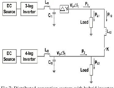
For understanding the power flow in
interconnecting line, the single line diagram of DG system with hybrid inverter interfaces is shown in Fig.7. In this section, analysis of power flow in interconnecting
line is carried out as given in [11].From the above study it is clear that for unbalanced load on
Fig.7: Distributed generation system with hybrid inverter interfaces.
4-leg inverter side, the negative and zero sequence components in terminal voltages of DG units are within acceptable limits specified by the above mentioned standards. The zero sequence currents never contribute to the power flow in interconnecting line [15]. The negative sequence component in terminal voltages is not negligible. Hence for calculating instantaneous power, positive and negative sequence components of currents as well as voltages are considered [11]. The 3-phase terminal voltages and interconnecting line currents are represented in the form of phasors as:
(2)
(3)
Here superscripts p and n denote respectively the positive and negative sequence component. The coefficients for all sequence components like , , etc., are vectors. In generalized way, they are represented as:
(4)
Instantaneous power in the interconnecting line is given as:
(5)
(6)
Where
The dc components P01 and P02 contribute to the average power flow. In case of DG system formed using two 4-leginverters as given in [11], it is shown that and δ12 = δ1 − δ2 is the load angle between two units.
(7)
It is further shown in [11] that due to both 4-leg inverter interfaces, terminal voltages of DG units are almost balanced and average power P01 is due to positive sequence components of voltages and currents. Hence the power sharing between two units is as per droop laws. However in the proposed DG system with hybrid inverter interfaces, the average power is also due to negative sequence components of voltages and currents (P02) and this component does not allow P1 and P2 to follow exact sharing in proportion to the droop coefficients. This justifies the slight difference in power sharing after load unbalance. Also2ω oscillations in the power are due to the negative sequence components. This oscillating power shared by each inverter depends on the network parameters and output impedance of inverters.
In the present study only active power flow in hybrid system is studied and hence only resistive loads are considered. But Q-V droop laws can be applied for reactive power sharing. There active power flow will also show 2ω oscillations as derived in (7).
IVINTRODUCTIONTOFUZZYLOGIC
CONTROLLER
L. A. Zadeh presented the first paper on fuzzy set theory in 1965. Since then, a new language was developed to describe the fuzzy properties of reality, which are very difficult and sometime even impossible to be described using conventional methods. Fuzzy set theory has been widely used in the control area with some application to dc-to-dc converter system. A simple fuzzy logic control is built up by a group of rules based on the human
knowledge of system behavior. Matlab/Simulink
simulation model is built to study the dynamic behavior of dc-to-dc converter and performance of proposed controllers. Furthermore, design of fuzzy logic controller can provide desirable both small signal and large signal dynamic performance at same time, which is not possible with linear control technique. Thus, fuzzy logic controller has been potential ability to improve the robustness of dc-to-dc converters. The basic scheme of a fuzzy logic controller is shown in Fig 5 and consists of four principal components such as: a fuzzification interface, which converts input data into suitable linguistic values; a knowledge base, which consists of a data base with the necessary linguistic definitions and the control rule set; a decision-making logic which, simulating a human decision process, infer the fuzzy control action from the knowledge of the control rules and linguistic variable definitions; a de-fuzzification interface which yields non fuzzy control action from an inferred fuzzy control action [10].
Fig.8. General Structure of the fuzzy logic controller on closed-loop system
Fig.9. Block diagram of the Fuzzy Logic Controller (FLC) for dc-dc converters
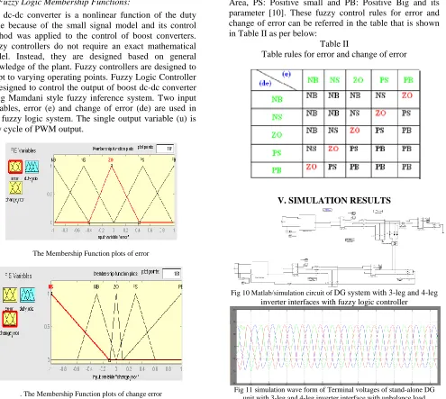
A. Fuzzy Logic Membership Functions:
The dc-dc converter is a nonlinear function of the duty cycle because of the small signal model and its control method was applied to the control of boost converters. Fuzzy controllers do not require an exact mathematical model. Instead, they are designed based on general knowledge of the plant. Fuzzy controllers are designed to adapt to varying operating points. Fuzzy Logic Controller is designed to control the output of boost dc-dc converter using Mamdani style fuzzy inference system. Two input variables, error (e) and change of error (de) are used in this fuzzy logic system. The single output variable (u) is duty cycle of PWM output.
The Membership Function plots of error
. The Membership Function plots of change error
the Membership Function plots of duty ratio
B. Fuzzy Logic Rules:
The objective of this dissertation is to control the output voltage of the boost converter. The error and change of error of the output voltage will be the inputs of fuzzy logic controller. These 2 inputs are divided into five groups; NB: Negative Big, NS: Negative Small, ZO: Zero Area, PS: Positive small and PB: Positive Big and its parameter [10]. These fuzzy control rules for error and change of error can be referred in the table that is shown in Table II as per below:
Table II
Table rules for error and change of error
V. SIMULATION RESULTS
Fig 10 Matlab/simulation circuit of DG system with 3-leg and 4-leg inverter interfaces with fuzzy logic controller
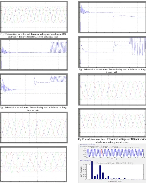
Fig 12 simulation wave form of Terminal voltages of stand-alone DG unit with 4-leg inverter interface with unbalance load
Fig 13 simulation wave form of Power sharing with unbalance on 3-leg inverter side.
Fig 14 simulation wave form of Terminal voltages of DG units with unbalance on 3-leg inverter side.
Fig 15 simulation wave form of Power sharing with unbalance on 4-leg inverter side
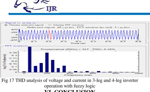
Fig 17 THD analysis of voltage and current in 3-leg and 4-leg inverter operation with fuzzy logic
VI. CONCLUSION
This paper presents a novel method to improve the power quality at point of common coupling for a3-phase 4-wire DG system using PI controller and fuzzy logic controller for grid interfacing inverter. The grid interfacing inverter is effectively utilized for power conditioning. This approach eliminates the additional power conditioning equipment to improve power quality at PCC. The grid interfacing inverter with the proposed approach can be utilized to inject real power generation from RES to the grid, and operate as a shunt Active Power Filter (APF). The current unbalance, current harmonics and load reactive power, due to unbalanced and non-linear load connected to the PCC, are compensated effectively such that the grid side currents are always maintained as balanced and sinusoidal at unity power factor. Moreover, the load neutral current is prevented from flowing into the grid side by compensating it locally from the fourth leg of inverter. When the power generated from RES is more than the total load power demand, the grid-interfacing inverter with the proposed control approach not only fulfils the total load active and reactive power demand (with harmonic compensation)but also delivers the excess generated sinusoidal active power to the grid at unity power factor. The settling of the system is improved hence proposed fuzzy logic controller has fast response, high accuracy of tracking the DC-voltage reference, and strong robustness to load sudden variations.
REFERENCES
[1] M. Dai, M. N. Marwali, and A. Keyhani, “A three-phase four wire inverter control technique for a single distributed generation unit in island mode,” IEEE Transactions on Power Electronics, vol. 23, no. 1,pp. 322–330, 2008.
[2] S. El-Barbari and W. Hofmann, “Digital control of a four leg inverter for standalone photovoltaic systems with unbalanced load,” in Twenty-sixth Annual conference of IEEE, IECON, (Nagoya, Japan), pp. 729–734,October 2000.
[3] X. Song, Y. Wang, W. Hu, and Z. Wang, “Three reference frame control scheme of 4-wire grid-connected inverter for micro grid under unbalanced grid voltage conditions,” in Twenty-Fourth Annual IEEE Applied Power Electronics Conference and Exposition, (Washington,USA), pp. 1301–1305, February 2009.
[4] M. N. Marwali and A. Keyhani, “Control of distributed generation systems - Part I : voltages and currents control,”
IEEE Transactions on Power Electronics, vol. 19, no. 6, pp. 1541–1550, 2004.
[5] M. N. Marwali and A. Keyhani, “Control of distributed generation systems - Part II : load sharing control,”IEEE Transactions on Power Electronics, vol. 19, no. 6, pp. 1551– 1561, 2004.
[6] I. Vechiu, H. Camblong, G. Tapia, B. Dakyo, and O. Curea, “Control offour leg inverter for hybrid power system applications with unbalanced load,” Energy Conversion and Management, vol. 48, no. 7, pp. 2119–2128, 2007.
[7] I. Vechiu, O. Curea, and H. C amblong, “Transient operation of a fourleg inverter for autonomous applications with unbalanced load,” IEEE Transactions on Power Electronics, vol. 25, pp. 399–407, February2010.
[8] R. Zhang, V. H. Prasad, D. Boroyevich, and F. C. Lee, “Three-dimensional space vector modulation for four-leg voltage-source converters,” IEEE Transactions on Power Electronics, vol. 17, no. 3,pp. 314–326, 2002.
[9] R. R. Sawant and M. C. Chandorkar, “A multifunctional four-leg grid connected compensator,”IEEE Transactions on Industry Applications, vol. 45, no. 1, pp. 249–259, 2009. [10] A. Kouzou, H. A. Rub, M. O. Mahmoudi, M. S. Boucherit, and R. Knennel, “Four wire shunt active filter based on four-leg inverter,”in International Aegean Conference on Electric Machines and Power Electronics &Electro motion, (Istanbul, Turkey), pp. 508–513, September 2011.
[11] D. Vyawahare and M. C. Chandorkar, “Power flow analysis in standalone 4-wire, 4-leg inverter microgrid with unbalanced loads,” inSixteenth European Conference on Power Electronics and ApplicationsEPE-ECCE, (Lappeenranta, Finland), pp. 1–10, August 2014.
[12] D. Vyawahare and M. C. Chandorkar, “Line interactive distributed 4-leg inverter system with unbalanced and nonlinear loads,” in IEEEInternational Conference on Power Electronics, Drives and EnergySystems (PEDES), (Mumbai, India), pp. 1–6, December 2014.
[13] M. P. Kazmierkowski, R. Krishnan, and F. Blaabjerg, Control in Power Electronics: Selected Problems. USA: Academic Press, 2002.
[14] M. J. Ryan, R. D. Lorenz, and R. W. D. Doncker, “Modeling of multi leg sine wave inverters: A geometric approach,” IEEE Transactions on Industrial Electronics, vol. 46, no. 6, pp. 1183–1190, 1999.