Computer Simulation to Generate Gaussian Pulses for UWB Systems
Ibrahim A. Murdas (Electrical Department, University of Babylon, Hilla ,Iraq)
Murad A. Al-Hello (Electrical Department, University of Babylon, Hilla ,Iraq)
269 Author(s)
Ibrahim A.Murdas
Electrical Department, University of Babylon, Hilla ,Iraq
E-mail:[email protected]
Murad A. Al-Hello
Electrical Department, University of Babylon, Hilla ,Iraq
E-mail: [email protected]
Computer Simulation to Generate Gaussian Pulses for UWB Systems
Abstract
In this work we present a computer simulation of a simple technique for the generation of power-efficient, FCC-compliant Ultra-Wideband (UWB) (monocycle and doublet) pulses. A Simulated system consist of a laser sources, semiconductor optical amplifier, optical modulator, fiber Bragg grating (FBG).This technique based on combination of optically reconfigurable photonic microwave delay-line filter and using the cross gain modulation (XGM) in Semiconductor Optical amplifier (SOA). In SOA the cross gain modulation (XGM) technique was used to produce a UWB monocycle pulse with a full width at half-maximum of 35 ps, by entering the output monocycle pulses from first stage to the second stage that included reconfigurable photonic microwave delay-line filter the last act as first- or second-order difference, which can be approximated as a first- or second-order derivative, after derivative the monocycle pulse the doublet pulses was obtained.
Keywords: Semiconductor Optical Amplifier, Cross Gain Modulation, Optical Signal Processing, Microwave Photonics
Introduction
Ultra wideband (UWB) is a fast emerging technology that has recently attracted considerable interest for its applications in
short-range, high-capacity wireless
communication systems and sensor networks, thanks to advantages such as a very high data rate, low power consumption, and immunity to multipath fading. Among these techniques, the implementation of the first- or the second-order derivatives of a Gaussian pulse, to generate a Gaussian monocycle or a Gaussian doublet, is considered as a simple and efficient technique for UWB pulse generation [R.J. Fontana 2004]. UWB pulses can be generated in the electrical domain using electronic circuitry. Recently; the generation of UWB pulses in the optical domain has been a topic of interest. The generation of UWB pulses in the optical domain provides a higher flexibility, which enables the generation of UWB pulses with switchable pulse shapes and polarities. In addition, the huge bandwidth offered by photonics enables the generation of UWB pulses to fully occupy the spectrum range
270 environmental changes would affect the
stability of the system.
UWB signals are produced by pulsed emissions, where a very wide RF bandwidth is related to a narrow pulse width. Unlike many conventional radio transmitters in which a modulated signal is up converted & amplified, in UWB systems information is encoded in the series of baseband pulses and transmitted without a carrier. Hence, the transmitters require precise pulse shaping to produce the required spectrum and maximise the antenna’s emission. Producing emissions with flat & wide PSDs requires extremely accurate pulse designs. Most of the approaches proposed for generating UWB signals with characteristic monocycle or doublet waveforms are implemented mainly by using electronic circuits in the electrical domain.[ Q. Wang and J. Yao, 2006] To distribute UWB signals over a longer distance, state-of the- art optical fiber with extremely low loss is considered an excellent candidate for a transmission medium. Therefore the generation and distribution of UWB signals directly in the optical domain has been a topic of interest recently.
The generate UWB doublets in the optical domain by using a specially designed frequency-shift keying modulator that consists of four optical phase modulators with three electrodes. In the same way the hybrid system for generating UWB monocycle signals in the gain-switched Fabry– Perot laser diode was used to generate an optical pulse train; a UWB monocycle signal is then produced in the electrical domain by a microwave differentiator [ Q. Wang and J. Yao, 2006], the generated UWB signals by using an optical phase modulator in combination with a length of single-mode fiber (SMF) was performed In Ref. [D. Wentzloff,2006], instead of a long SMF, a fiber Bragg grating (FBG) is employed as a frequency discriminator to perform PM– IM conversion. UWB monocycle or doublet signals can be generated by altering the location of the optical carrier at the linear or the quadrature slopes of the FBG spectral response.Recently proposed to generate UWB signals by using photonic microwave delay line as differentiated. Because Gaussian monocycle or doublet pulses can be generated by
implementing the first- or the second-order derivative of a Gaussian pulse this was achieved in [Q. Wang, J. Yao, 2007].
Gaussian Pulse Generation Mathematical analysis
Gaussian monocycle or doublet pulse can be generated by implementing the first- or the second-order derivative of a Gaussian pulse where the zero-mean Gauss function is described by Equation (1), where σ is the standard deviation [M. Ghavami et al 2007]:
(1)
Where: G(x) are called Gaussian waveforms because their mathematical definition is similar to the Gauss function.
The basis of these Gaussian waveforms is a Gaussian pulse represented by the following Equation
(2)
Where: yg1 is the basis of the Gaussian pulse, −∞ < t < ∞, τ is the time-scaling factor, and K1 is a constant. More waveforms can be created by a sort of high-pass filtering of this Gaussian pulse. Filtering acts in a manner similar to taking the derivative of Equation (2). For example, a Gaussian monocycle, the first derivative of a Gaussian p ulse, has the form:
(3)
Where: yg2 is the first derivative of a Gaussian
pulse , −∞ < t < ∞ , τ is the time-scaling factor and K2 is a constant. A Gaussian monocycle has a single zero crossing. Further derivatives yield additional zero crossings, one additional zero crossing for each additional derivative. If the value of τ is fixed, by taking an additional derivative, the fractional bandwidth decreases, while the centre frequency increases. A Gaussian doublet is the second derivative of equation (3) and is defined by [M. Ghavami et al 2007]
2 2 2 2
2
1
)
(
xe
x
G
2 ) ( 1 1(
)
t g
t
K
e
y
2
)
(
2
2
2
)
(
2
t
e
t
K
t
g
271
(4)
Where: yg3 is the second derivative of a Gaussian pulse, −∞ < t < ∞, τ is the time-scaling factor and K3 is a constant.
After generating the optical monocycle pulses by using the optical amplifier the doublet Gaussian pulses can be generated according to equation (4). The second -order derivative of Gaussian pulses can be approximated by the first- or the second-order difference. It is known that the a second-order difference can be realized using a three-tap microwave delay-line filter with coefficients of (1, -2, 1) [Q. Wang and J. Yao, 2007 ].
Principle of photonic microwave delay line filter
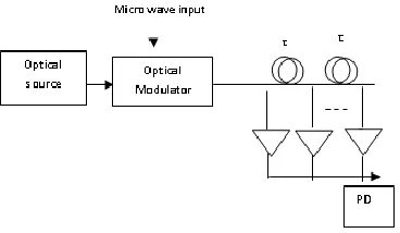
Fig. (1) Illustrate the principle of photonic microwave delay line filter [Q. Wang and J. Yao, 2007]
The schematic diagram of a general N-tap photonic microwave delay-line filter is shown in Fig. 1. It consists of an optical source, an optical modulator, a delay tine device, and a photodetector (PD). The microwave signal to be filtered is modulated onto the lightwave generated from the optical source via the optical modulator. The modulated lightwave is then sent to an N-tap delay-line device to introduce different time delays with an identical time delay difference between two adjacent taps. The time-delayed signals are then applied to the PD. The time delay difference determines the free spectral range (FSR) and the coefficients determine the shape of the filter response. Mathematically, the
frequency response of an N-tap microwave delay-line filter is given [Q. Wang and J. Yao, 2007]
…. (5)
Where HN (
) is the frequency response of delay–line filter, τ is the time delay difference and ak is the coefficient of the kth tap. For a two-tap filter with coefficient of (1,-1), the frequency response is given [Q. Wang and J. Yao, 2007](6)
For a threetap filter with coefficients of (1, -2, 1), the frequency response is given
(7)
If ωτ / 2 is small, Eq. 2 and 3 can be
approximated as
(8)
2.3 Generation monocycle Gaussian pulse We simulate a simple method for generating UWB monocycle pulses based on cross-gain modulation (XGM) in a optical amplifier (SOA) as shown in Fig.(2) . In this system an optical Gaussian pulse (pump) and a continuous wave (CW)( probe) are applied to theSOA. The XGM in the SOA, a pair of polarity-reversed optical Gaussian pulses is generated at the output of the SOA [Q. Wang and J. Yao, 2006].
The two polarity-reversed optical pulses are then time delayed by two cascaded FBGs to introduce a time-delay difference. When the physical spacing between the two FBGs and their reflectivities are properly designed, a monocycle pulse with the required design parameters is generated.
2 ) ( 2 2 2 3 3
)
2
1
(
2
)
(
t ge
t
K
t
y
je
H
2
sin
4
)
(
2 3 2 / 22
sin
2
)
(
j e
j
H
je
H
3(
)
2 2 2 2
(
)
je
j
H
1 0)
(
N k jk kN
a
e
272 Fig. (2) Monocycle pulse generation system
[Q. Wang and J. Yao, 2006]
The basic idea of this approach is to generate a pair of polarity-reversed pulses at different wavelengths with an appropriate time delay difference between the pulses. The material gain spectrum of an SOA is homogenously broadened therefore the cross gain modulation (XGM) effect in an SOA is used to generate the polarity-reversed pulses. In the proposed approach, when a high-power pulsed pump light is injected into the SOA, the variation of the pump power modulates the carrier density of the SOA so that the gain of the SOA varies inversely with the input laser power. If a CW probe light is injected into the SOA with the pump, the power of the probe light will vary inversely with the pump power, and a pair of polarity-reversed pulses is generated, with one pulse at the pump wavelength and the other at the probe wavelength, the non-linear mechanism is (XGM) illustrated in Fig. (3)Since the polarities of the pump and the probe pulses are reversed, a direct detection of these two pulses would lead to a cancellation of the two pulses. However, if a proper time-delay difference is introduced between the two pulses, a new pulse that has a shape of a monocycle is generated. The pulse width of the monocycle can be controlled by altering the time-delay difference.
Fig. (3) Illustration the XGM mechanism in SOA
Doublet Gaussian pulses
If the input signal to the three-tap microwave delay-line filter is a Gaussian monocycle, a Gaussian doublet can be generated. This will be illustrated in Fig. (4) where the monocycle pulses was generated and entering to the photonic delay- line filter the output wave (doublet) taken at the BPD.
(4) The completed proposed switchable system to produce the monocycles and doublet Gaussian pulse
The Simulation Results
A simulation was achieved by using OptiSystem7 and Matlab packages .the system layout a shown In figure (4) was simulated with two parts one for monocycle and for doublet. The two laser sources are used one for the pump signal and the other for probe signal. The pump source was modulated by electrical data using pseudo random bit sequence generator and NRZ data format while the other laser source used as CW probe data , the pump and probe are combined together into SOA using coupler. According to XGM technique the intensity of probe data was modulates according the large power of pump signal and the pulse with shape shown in Fig. (6) are produced at the output of SOA, using filter like FBGs filters tuned at pump– probe wavelengths to chancel the time delay
SOA
Pum p
Pro be C
W
Filter Modulate
d probe ti
me ti
273 .Fig(5) shows the XGM where a strong pump
light will reduction the gain of SOA, and causes to modulation of a weak CW probe light .
Fig. (5) Gain reduction due to Strong pump pulse
The pump power is usually higher than the probe power, a certain asymmetry will occur in the generated monocycle as shown in Fig. (6).
.
Fig. (6) Asymmetry monocycle pulse
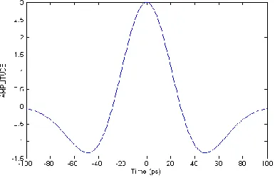
Monocycle that has a very good shape is obtained, as shown in Fig.( 7). The FWHM of the monocycle pulse is about 35 ps, which is narrower than electronic generated Gaussian pulse. This is because the time-delay difference between the pump and the probe pulse is smaller than the width of the Gaussian pulse.
Fig. (7) output monocycles Gaussian pulse
Now after the monocycles was generated the system in Fig.(4) can used to generate the doublet Gaussian pulses if it’s configured as a three-tap microwave delay-line filter with coefficients of (1, -2, 1). This configuration was achieved by connected the two arm of the coupler to the input port of the BPD, with an additional time-delay difference τ introduced between the two branches by adjusting the internal optical delay line in the BPD the doublet pulses with FWHM =25 ps are shown in figure (8).All parameter used in the simulation shown in table 1.
Fig.(8) Doublets Gaussian pulse at the output of system
Table 1: Simulated parameter
Parameter Value
Pump wavelength 1549.2 μm
Probe wavelength 1552.63 μm
Fibers Bragg Grating length
(1, 2) 2mm
Driving current to the SOA 300 mA
output power of laser source
(probe) - 7 dbm
output power of laser source
(pump) -3 dbm
Spacing between FBG1 and
FBG2 2.5 mm
Input Pulse shape Gaussian
Length of SOA 100 μm
Carrier density 10^24 m-3
tFWHM 30 ps
Volume of SOA 90 μm3
274 Conclusions
We present a simple flexible method for generating UWB pulses (monocycle and doublet) based on delay-line filter and the XGM in SOA. The numerical experiment implemented using Mat lab and OptSystem package to generated monocycles have 35 ps at FWHM.When the Gaussian monocycle pulses were generated. the filter was configured as a three-tap delay-line filter with coefficients of (1, -2, 1), to generate a Gaussian doublet pulses with 25 ps at FWHM.
References
D. Wentzloff,, A. Chandrakasan (2006) “Gaussian Pulse Generators for Subbanded
Ultra-Wideband Transmitters” IEEE
Transaction on microwave theory and Techniques Vol ,54, NO. 4, pp. 1647-1650. J. Yao, Q.Wang, (2007) “Photonic Microwave Bandpass Filter With Negative Coefficients Using a Polarization Modulator” IEEE Photonics Technology Letters Vol 19, NO. 9, pp. 644-646.
J. Li, K.Xu,(2007) “Ultra-wideband pulse generation with flexible pulse shape and polarity control using a sagnac interferometer– based intensity modulator” Optics Express, Vol 15, No.26,pp.18156-18161.
L. Zuniga, P. Petropoulos (2006) Design of a Fiber Bragg Grating for Decoding DPSK Signals Optoelectronics Research Centre, University of Southampton, United Kingdom. M. Ghavami, L. B. Michael, R. Kohno (2007) Ultra Wideband Signals and Systems in Communication Engineering Copyright @ 2007 John Wiley & Sons Ltd.
Q. Wang , F. Zeng,( 2006) “Optical ultra wideband monocycle pulse generation based on cross-gain modulation in a semiconductor optical amplifier” Optics Letters,Vol 31, No.21, pp3083-3085.
Q. Wang and J. Yao, (2006) “UWB doublet generation using a nonlinearly-biased electro-optic intensity modulator,”IEE Electron. Letter, Vol. 42 ,pp 1304-1305.
Q. Wang and J. Yao, (2007) “ Switchable optical UWB monocycle and doublet generation using a reconfigurable photonic
microwave delay-line filter”, Optics Express Vol.15, No. 22 pp 14667-14672.
R. J. Fontana, (2004) “Recent System Applications of Short-Pulse Ultra-Wideband
(UWB) Technology”,IEEE Transaction
Microwave Theory and Technique. Vol. 52, pp. 2087-2104.
R.J. Fontana, E. A. Richley,(2007) Observations on Low Data Rate, Short Pulse UWB Systems IEEE International Conference on Ultra-Wideband (ICUWB), Singapore.
.
![Fig. (2) Monocycle pulse generation system [Q. Wang and J. Yao, 2006]](https://thumb-us.123doks.com/thumbv2/123dok_us/8254097.1374981/5.522.283.455.177.375/fig-monocycle-pulse-generation-q-wang-j-yao.webp)