Available Online atwww.ijcsmc.com
International Journal of Computer Science and Mobile Computing
A Monthly Journal of Computer Science and Information Technology
ISSN 2320–088X
IMPACT FACTOR: 6.017
IJCSMC, Vol. 5, Issue. 12, December 2016, pg.13 – 18
Horn Antenna with a
Specific Radiation Pattern
Lukas Wezranowski, Zdenek Urban, Lubomir Ivanek
Department of Electrical Engineering VŠB TUO, Ostrava, Czech Republic[email protected]; [email protected]; [email protected]
Abstract— This document deals with a horn antenna deigned to heat objects. Horn antenna is one of the simplest and frequently used antennas in telecommunications technology. When using these antennas, maximum directivity is in most cases required – the narrowest directivity pattern is desired. The described antenna however, serves as the heating for material that is placed near the antenna aperture; so that it requires the widest directivity pattern – the smallest directivity is desired. This article describes the process of testing and individual possibilities of gaining the widest possible directivity pattern. Designed antennas were simulated in the CST microwave studio.
Keywords— Antenna, aperture, radiation pattern, material heating
I. INTRODUCTION
Horn antenna is frequently used in microwave technology as feed element; in communications technology; and it has even wider usage in radio astronomy – satellite monitoring, etc. One of its possible utilizations is to heat objects, that are placed close to the antenna aperture. There are many reasons for doing that – drying of the material, elimination of molds, melting materials with low melting point etc. Our aim is to primarily heat space with increased humidity and to melt materials, so that the ICM frequency 2,4 GHz emitting through the magnetron was used. The resulting product has to complain with strict safety policies. It cannot be dangerous to human tissue.
We have to remember, that the standard antenna dimensions and its common usage is mainly for radio-communication applications, therefore it needs to have the highest directivity possible. Concerning the above mentioned fact, the antenna design has to be modified and changed for the purpose of heating.
Basic antenna designs and ideas on how to achieve the widest radiation pattern possible:
Use of meta - material lenses
Use of multiple diffraction
Changing the shape of emitter
II. EXTENSION OF THE RADIATION PATTERN WITH META-MATERIAL LENSES
This variant was one of the possibilities. Meta-material lenses have attributes, that can change the source of radiation. It is a brand new approach to controlling the amplitude and phase of electromagnetic field distribution above the opening of the horn antenna. Narrowing the amplitude in the area of the aperture and suppressing lateral (parasitic) lobes of antenna radiation is achieved by inserting the meta-material lens. Meta-material lenses are, in addition, adapted to gain distribution of the flat stage. All that is necessary to prevent lowering of high antenna gain, which is significant for horn antennas. It is also given by the construction of the antenna and its parts. The lenses can be used also for increasing the area of radiation.
A. Mechanism of manipulating aperture fields
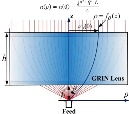
The basic theory of the GRIN metamaterial has been performed in Ref. 8. It has been shown that the wave front can be manipulated by a GRIN lens. Here, we will demonstrate further that the GRIN metamaterials can not only be used to transform a spherical wave to a plane wave, they can also be employed to manipulate the distribution of the aperture field including magnitude and phase simultaneously. [2]
( ) ( ) √ (1)
Fig. 2 The schematic diagram of manipulating aperture field using GRIN lens. [2]
B. Design of the metamaterial-loaded horn antenna
Fig. 3 The topology of the proposed antenna. [2]
Figure 4 shows what effect the meta-material lenses have. In this particular case, the radiation pattern is channeled for higher directivity. Nonetheless, as it was mentioned above, those meta- material lenses can be used with reverse effect – for widening the radiation pattern. [2]
Fig. 4 Electric field in E-plane of horns and amplitude of the electric field on the aperture. [2]
This method is however financially demanding because every meta-material lens is quite hard to obtain. The lens needs to be also adjusted for the purpose of heating according to the antenna dimensions and it has to complain with the conditions for usage with magnetron emitter. This method was developed only theoretically. Planned simulations in CST studio program had not been realized in the end because of high financial demands and the difficulty of realization.
III.EXTENSION OF THE RADIATION PATTERN WITH THE USE OF MULTIPLE DIFFRACTION
Another option is a diffraction or a multiple diffraction. This idea comes from optoelectronics, where diffraction grids are used for bending of light, so that the light waves can get even into the area of geometric shade. The light is therefore able to get behind the barrier, because its rays are bent.
Fig. 5 The principle of diffraction.
Fig. 6 a) a common horn antenna – radiation and the impact of waves. b) a horn antenna with diffraction layers – radiation and the impact of waves.
In principal, it could be a grid, eventually embedded wires as obstacles that “breaks” the signal and the emitting diagram is enlarged. The first phase of simulations was done with gradual insertion of wires into the model.
Fig. 7 optional shapes of horn antenna
Fig. 8 more appropriate antenna shapes
The shape of the antenna shown on figure 8 was much more appropriate for thermal application. As we can see, the gradual insertion of grids helps channeling the radiation pattern. You have to be aware that if you add too much grids, the signal can be reflected back. This case is shown in the last diagram.
It is evident, from measurement and simulations, that the antenna shape is more suitable for usage than the previous shape; nonetheless, the diffraction grids have rather negative effects and the waves are reflected back towards the emitter. This was the reason for testing the option with changed size and shape of the emitter.
IV.EXTENSION OF THE RADIATION PATTER WITH CHANGING THE SHAPE OF THE EMITTER
Antennas with wide emitting angle are already used in practice but they are used for different frequencies and for purposes other than material heating.
V. CONCLUSIONS
In the process of designing horn antennas for material heating two types of antennas were modeled. The cylindrical horn antennas, which – as it turned out - were inapplicable to our case and antennas with rectangular aperture. Antennas were modified by inserting the lenses and other conductive objects of different shapes. As the most appropriate were antennas according to figure 8.
ACKNOWLEDGEMENT