University of South Florida
Scholar Commons
Graduate Theses and Dissertations Graduate School
January 2013
Real-Time Map Manipulation for Mobile Robot
Navigation
Carlos Favis Ezequiel
University of South Florida, [email protected]
Follow this and additional works at:http://scholarcommons.usf.edu/etd
Part of theComputer Sciences Commons
This Thesis is brought to you for free and open access by the Graduate School at Scholar Commons. It has been accepted for inclusion in Graduate
Scholar Commons Citation
Ezequiel, Carlos Favis, "Real-Time Map Manipulation for Mobile Robot Navigation" (2013).Graduate Theses and Dissertations.
Real-Time Map Manipulation for Mobile Robot Navigation
by
Carlos Ezequiel
A thesis submitted in partial fulfillment of the requirements for the degree of Master of Science in Computer Science Department of Computer Science and Engineering
College of Engineering University of South Florida
Major Professor: Luther Palmer III, Ph.D. Yu Sun, Ph.D.
Sudeep Sarkar, Ph.D.
Date of Approval: March 25, 2013
Keywords: mapping, obstacle-avoidance, path-planning, user-interface, teleoperation Copyright c2013, Carlos Ezequiel
DEDICATION
ACKNOWLEDGMENTS
First and foremost, I would like to thank my thesis adviser, Dr. Luther Palmer for his patience, guidance and support of my research. I would also like to thank the committee members, Dr. Yu Sun and Dr. Sudeep Sarkar, for giving supportive feedback on how to improve this work.
I would like to thank the following people who contributed to this thesis: Mayur Palankar, for helping me format this thesis manuscript in Latex and for assisting me with my various printing needs, Daniel Standish, for giving me a quick tutorial on the PRM algorithm and Matlab and his input on video streaming options for the robot, and for providing me with some sample code, and Robert Skinner, for helping me conduct user perception tests on multiple participants.
I would like to acknowledge the Fulbright program for enabling me to study in the United States through a graduate scholarship.
Lastly, I would like to thank my father for his continued support of my education.
TABLE OF CONTENTS
LIST OF TABLES iii
LIST OF FIGURES iv ABSTRACT vi CHAPTER 1: INTRODUCTION 1 1.1 Problem 1 1.2 Research Objectives 1 1.3 Research Approach 2 1.4 Applications 3 1.5 Thesis Organization 3
CHAPTER 2: LITERATURE REVIEW 4
2.1 Highly Autonomous Approach 5
2.2 Teleoperated Approach 10 2.2.1 Haptic Feedback 11 2.2.2 Augmented Reality 12 2.2.3 Interface Evaluation 13 2.3 Semi-Autonomous Approach 15 2.3.1 Single-Robot Interfaces 15 2.3.2 Multi-Robot Interfaces 16 2.3.3 Interface Evaluation 17 2.3.4 Scene Manipulation 19 2.4 Summary 20
CHAPTER 3: PATH PLANNING ALGORITHMS 22
3.1 Potential Fields 23
3.2 Probabilistic Road Map 26
CHAPTER 4: ROBOT SYSTEM 34 4.1 Robot Hardware 34 4.2 Hardware-Software Deployment 36 4.3 Proprietary Software 38 4.3.1 ARIA 38 4.3.2 ArNetworking 38 4.3.3 ARNL 39 4.3.4 SONARNL 39 4.3.5 MobileEyes 39 4.3.6 MobileSim 40 4.3.7 Mapper3Basic 40 4.4 System Modifications 41 4.4.1 Navigation Algorithm 42
4.4.2 Robot Navigation Interface 43
CHAPTER 5: TEST METHODOLOGY 47
5.1 Test Setup 47
5.1.1 Simulation Test 47
5.1.2 Real-World Test 48
5.2 Test Description 50
5.2.1 Navigation Test 50
5.2.2 User Perception Test 51
CHAPTER 6: TEST RESULTS 58
6.1 Navigation Test Results 58
6.2 User Perception Test Results 62
6.2.1 Image Test Results 62
6.2.2 Video Test Results 66
6.2.3 Image Versus Video Results 70
6.2.4 User Survey 71
CHAPTER 7: CONCLUSION 72
LIST OF REFERENCES 74
APPENDICES 78
Appendix A: User Perception Test Survey Form 79
LIST OF TABLES
Table 3.1 Computation times of PRM using random samples in the free
configu-ration space. 29
Table 3.2 Computation times of PRM using fixed samples in the free
configura-tion space. 30
Table 3.3 Computation times of PRM-A*. 32
Table 3.4 Computation times for PRM-A* path planning with two waypoints and
four obstacles. 33
Table 4.1 Pioneer 3-DX specifications. 35
Table 4.2 Laptop specifications. 36
Table 4.3 Path planning parameters that were not modified. 44
Table 4.4 Modified path planning parameters. 45
Table 5.1 Navigation test description. 51
LIST OF FIGURES
Figure 3.1 GUI depicting a path planning simulation using potential fields, where
the map has two waypoints. 25
Figure 3.2 GUI depicting a path planning simulation using potential fields, where
the map has two waypoints and one user-defined obstacle. 26
Figure 3.3 GUI simulation where planner was unable to reach the goal due to local
minimum. 27
Figure 3.4 PRM simulation using random samples from free configuration space. 28 Figure 3.5 PRM simulation use grid of samples, where samples that fall within
obstacles are excluded. 30
Figure 3.6 GUI-based path planning simulation using PRM and A* algorithms. 31 Figure 3.7 GUI-based path planning simulation having two waypoints and four
obstacles. 32
Figure 4.1 Adept MobileRobots Pioneer 3-DX Mobile Robot. 34
Figure 4.2 Pioneer 3-DX with laptop computer. 36
Figure 4.3 Robotic system hardware-software architecture. 37
Figure 4.4 MobileEyes GUI. 40
Figure 4.5 MobileSim GUI. 41
Figure 4.6 Mapper3Basic GUI. 42
Figure 4.8 Robot Navigation Interface (RNI). 46
Figure 5.1 Remote navigation setup for simulation tests. 49
Figure 5.2 Remote navigation setup for real-world tests. 50
Figure 5.3 Hallway used in Test1A and 1B. 53
Figure 5.4 Obstacle placement for Test 1A. 54
Figure 5.5 Obstacle placement for Test 1B. 54
Figure 5.6 Image-based interface setup for Test 1A. 55
Figure 5.7 Image-based interface setup for Test 1B. 55
Figure 5.8 Hallway used in Test 2. 56
Figure 5.9 Video-based interface setup for Test 2. 57
Figure 6.1 Real-world test with 3 obstacles placed separately. 60
Figure 6.2 Real-world test with 5 obstacles placed overlapping with each other. 61
Figure 6.3 Error over distance for image-based Test 1A. 63
Figure 6.4 Error over distance for image-based Test 1B. 64
Figure 6.5 Error over distance for image-based Test 2. 65
Figure 6.6 Error over distance for all image-based tests. 66
Figure 6.7 Error over distance for video-based Test 1A. 67
Figure 6.8 Error over distance for video-based Test 1B. 68
Figure 6.9 Error over distance for video-based Test 2. 69
Figure 6.10 Error over distance for all video-based tests. 69
ABSTRACT
Mobile robots are gaining increased autonomy due to advances in sensor and com-puting technology. In their current form however, robots still lack algorithms for rapid perception of objects in a cluttered environment and can benefit from the assistance of a human operator. Further, fully autonomous systems will continue to be computation-ally expensive and costly for quite some time. Humans can visucomputation-ally assess objects and determine whether a certain path is traversable, but need not be involved in the low-level steering around any detected obstacles as is necessary in remote-controlled systems. If only used for rapid perception tasks, the operator could potentially assist several mobile robots performing various tasks such as exploration, surveillance, industrial work and search and rescue operations. There is a need to develop better human-robot interaction paradigms that would allow the human operator to effectively control and manage one or more mobile robots.
This paper proposes a method of enhancing user effectiveness in controlling multi-ple mobile robots through real-time map manipulation. An interface is created that would allow a human operator to add virtual obstacles to the map that represents areas that the robot should avoid. A video camera is connected to the robot that would allow a human user to view the robot’s environment. The combination of real-time map editing and live video streaming enables the robot to take advantage of human vision, which is still more effective at general object identification than current computer vision technology. Experimental
results show that the robot is able to plan a faster path around an obstacle when the user marks the obstacle on the map, as opposed to allowing the robot to navigate on its own around an unmapped obstacle. Tests conducted on multiple users suggest that the accuracy in placing obstacles on the map decreases with increasing distance of the viewing apparatus from the obstacle. Despite this, the user can take advantage of landmarks found in the video and in the map in order to determine an obstacle’s position on the map.
CHAPTER 1: INTRODUCTION
Autonomous mobile robot navigation through complex and dynamic environments is an ongoing challenge. Although advances in sensor technology, computing power and path planning algorithms have allowed mobile robots to perform at a high level of autonomy in navigating through cluttered space, reliability and cost-effectiveness is still a major con-cern. Human perception is still more advanced than machine vision in performing general object recognition tasks. In addition, increasing the number of sensors on a robotic system greatly increases its development and maintenance costs. Path planning also becomes more computationally expensive. Thus, there is a need to have a human-in-the-loop of a robotic system in order to augment the robot’s perception and judgement.
1.1 Problem
The manner in which a human operator interacts with a robotic system in order to improve the latter’s navigation is an enduring problem that has a number of different solutions and implications. The main question is "How can one best capitalize a human operator’s perception and path planning skills to improve robot locomotion in a complex environment?" This work investigates how one can best use a human operator in a human-machine collaborative framework.
1.2 Research Objectives
The goal of the project is to investigate the degree of effectiveness of having a human-in-the-loop to aid in robot movement as opposed to allowing the robot to navigate
to a designated goal on its own. Our primary measure of effectiveness would be the time it takes for the robot to reach the goal from a certain location. However, the following factors were also considered:
• Usability of the map-based navigation interface
• User accuracy in identifying obstacles and placing forbidden regions in the correct positions on the map
1.3 Research Approach
In order to address the robot navigation problem, a map-based robot navigation interface (RNI) was created, which would allow the human operator to manipulate the robot’s map in real-time. The operator will be able to assist the robot in identifying obstacles that the latter cannot perceive through its sensors. The operator could to relay this information to the robot by adding virtual obstacles to represent the unmapped obstacles on the map, and could then send this map easily using the RNI software. A video camera was used so that the operator can see the forward view of the robot. A third-party application was used for live video streaming to the operator’s control software.
The advantage of this approach is that the robot can make use of a human operator’s perception, which is faster and more accurate at identifying obstacles in a variety of shapes and sizes than its on-board sensors. The interface would enable the operator to give the robot a few "hints" on the best path to go, without directly changing the path. Since the robot can navigate autonomously, it frees the human operator to perform other tasks, such as monitoring other robots. The system would enable one human operator to potentially control and change the paths of multiple robots simultaneously.
1.4 Applications
The method can be used to develop systems that would allow a group of robots to navigate in a cluttered environment, such as a warehouse, or to perform multiple search and rescue operations simultaneously. An operator looking through the video feed of one robot can identify a hazardous area, such as an oil spill, toxic waste spill or hole in the ground, and mark an obstacle on the map to indicate to the other robots that the area is not traversible. Another application would be for real-time mapping of an unknown environment that would allow for human operator to identify obstacles or areas of interest and mark them on the map in real time.
1.5 Thesis Organization
Chapter 2 discusses related work done to address the problem of mobile robot navigation. Chapter 3 discusses path planning algorithms that were considered in the robot system used. Chapter 4 describes the robot system’s hardware and software architecture. Chapter 5 explains how the test was setup in order to determine the robot’s navigation with map manipulation, as well as the user’s capabilities for identifying obstacles at a distance. Chapter 6 summarizes the test results. Finally, the conclusion and recommendations for future work are given in Chapter 7.
CHAPTER 2: LITERATURE REVIEW
Much work has been done on improving autonomous navigation by mobile robots [1]. There are three general approaches to mobile robot navigation: (1) highly autonomous, (2) teleoperated and (3) semi-autonomous.
The highly autonomous approach focuses on developing systems that allow the robot to navigate in an environment with very little or no human control. This approach seeks to reduce the need to have a skilled robot operator controlling the robot. Such systems, however, would often need multiple sensors and advanced algorithms, which may be both financially and computationally expensive. Reliability is also a concern, as the robot may malfunction and cause damage without a human operator to take emergency responsive action.
The teleoperated, or "drone-type," approach seeks to enhance a human operator’s ability to fully control a mobile robot . This approach is currently used in military-type unmanned aerial vehicles (UAV) [2]. The advantage of this approach is that the system can be relatively inexpensive, with respect to sensors needed, and computationally inexpensive since path planning is done by the operator. The disadvantage is that it may require a high degree of human concentration and skill to control the robot effectively, especially for long-duration missions.
The semi-autonomous approach provides a compromise between the above two approaches. The robot would be able to navigate on its own, but a human operator is present to monitor, command or directly control the robot as needed.
In practice, most robot systems are semi-autonomous in nature, due to the need to have a human operator to ensure safe and effective operation [3]. One can think of the above approaches as having different levels of automation (LOA), with the highest being fully autonomous, and the being lowest manually controlled [4]. However, in order to develop a better understanding of the advantages and disadvantages of various levels, the various LOA are summarized into the three approaches described previously. Despite the necessity to have various LOA in order to effectively solve different problems, the current trend for mobile robot systems is to have higher LOA.
The following sections describe recent studies made in each of the three approaches to autonomous navigation, and how they relate to the method proposed in this study.
2.1 Highly Autonomous Approach
In this category, the emphasis is on how to develop highly autonomous navigation algorithms using a combination of different sensors.
Kala et al. [5] developed a navigation system using three different algorithms: genetic algorithm, artificial neural network and A*. The algorithms were run independently of each other. Their results show that using each of the three algorithms, the robot was able to navigate in an environment without collding with any moving obstacles. Also, their results showed that A* algorithm performed the best out of the three. Testing was done using simulation only.
The A* algorithm was considered in this work, due to its speed and simplicity com-pared to other navigation algorithms that were also considered. More detailed discussion can be found in Chapter 3.
Garrido et al. [6] proposed a sensor-based global path planning algorithm, which combined the global path planning that generates the optimal path towards a goal, with local planning for collision avoidance, in one step. The algorithm is based on the Voronoi Fast Marching (VFM) method. The algorithm computes both global and local path planning every step that the robot takes towards the goal. Although the computations are performed every step, it is relatively efficient, having a complexity O(n), where n is the number of cells in the grid that is generated from the map of the robot’s environment.
Testing was performed in simulated environment having an area of 2000m2(medium size). Performance was measured by taking the worst computation time of the algorithm during the simulation run. The worst time was found to be 150ms, which was considered acceptable for most applications. Despite the relative efficiency of the algorithm, its main limitation is still its computational complexity, especially for large environments, as well as the computational differences between the initial (near start) and final (near goal) of task execution.
The proposed work made use of a combined global and local path planning algo-rithm, as described in [6]. The algorithm used is explained in more detail in Chapter 4.
Cho et al. [7] explore the use of a laser range finder (LRF) for map-based robot navigation and localization in indoor environments. The study focuses on localization by comparing data from a predefined global map and data from the LRF. The global map is represented by features of vertices and patterns of vertices. The robot localizes by matching the vertices in the global map with those computed from LRF data. The technique can be applied to localize multiple robots with a common map.
Although use of a LRF improves the sensing capabilities of a mobile robot and aids in mapping, localization and navigation, the cost of the device may be prohibitively expensive, especially when building systems consisting of multiple heterogenous mobile
robots, such as in a manufacturing environment. The proposed work does not make use of a LRF for navigation due to cost considerations, but instead relies on sonar sensors and human vision. However, LRF integration is possible and would improve the system.
A method of localization and navigation using a monocular vision system was proposed by Ehtemam-Haghighi [8]. Self-localization is performed using a vision system, while path planning and obstacle avoidance by fusing data from both the vision system and a range of ultrasonic sensors. Localization is done using the vision system, which detects a pair of red and green lines on the floor known as landmarks. Obstacle avoidance is done using the Vector Field Histogram (VFH) method, which permits detection of unknown objects. Hough transform was used for edge detection.
The work shows that the robot was able to navigate through obstacles towards a given goal, and that the vision system was able to detect and avoid obstacles. However, the system was tested using opaque rectangular-shaped obstacles that had well-defined edges. Obstacles such as a fence or chair, which a human person can identify easily, may be more difficult to detect, and may require more advanced algorithms that are computationally expensive.
Another vision-based navigation paradigm is explored by Santosh et al. [9]. Here, they developed an image-based exploration algorithm, where the robot is able to explore and map an unknown frontier of its environment autonomously using images. Experimental results conducted in an unmodified laboratory corridor setting demonstrate the validity of the approach. This work focuses on mapping an unknown environment rather than navigation. It may possible to extend the method such that the system would be able to detect an unmapped obstacle in a known environment. This would require that the vision system detect obstacles from a far distance. The work, however, indicates that the camera
was tilted downwards by 30 degrees and has a field of view (FOV) of about 50 degrees, which limits the range at which it detects objects.
Correa et al. [10] examines the use of a Kinect sensor as low-cost vision system for mobile robot navigation. Navigation is performed both reactively, using Kinect depth images for distance estimation for collision avoidance, and deliberatively using artificial neural network (ANN) to identify key points (i.e. left turns, right turns, intersections) in Kinect images. The topological map represents hallways as edges and locations as vertices. Preliminary experiments reveal that the system was able to provide safe navigation for the robot in dark (no light) and light conditions. Also, the ANN subsystem, which after training had 316 neurons in the hidden layer and 8 neurons in the output layer, provided very good results on classifying features (92%).
The work demonstrates the capabilities of the Kinect for mobile robot navigation. However, more tests would be needed in complex environments to verify the practicality of the system. The Kinect sensor has a limited range and may not be able to pick up obstacles past a certain distance. However, it provides a low-cost way of sensing obstacles in the environment.
Tsalatsanis [11] studied the control of multi-sensor, multi-robot teams for industrial applications. The system is composed of a set of functional components perform navigation and obstacle avoidance using vision-system and sonar sensors, localization using Kalman filtering to fuse sensor data and fuzzy logic to estimate robot pose, target tracking based on vision system and laser range finder (LRF) for intruder detection and mission planning us-ing limited look-ahead control methodology based on finite automata theory. Experiments were done in both real indoor and outdoor environments to measure the performance of each functional component. The mission planning component, however, has only been validated in the simulated setting.
Urmson et al. [12] examine the development and performance of Boss, the au-tonomous vehicle that had won the 2007 DARPA Urban Challenge. The authors sum-marized several lessons learned by the team that developed Boss. First, off-the-shelf sensors were not sufficient to support autonmous driving in an urban environment. Also, no single sensor alone is capable of meeting the range and coverage demands of urban navigation. Second, mimicking human driving in an urban environment requires a rich representation of roads, curbs, and other obstacles. It was found that Boss waited equally long behind a stopped car and a barrel, while trying to differentiate between the two. A richer representation, however, would require better sensing capabilities and more complex object recognition algorithms.
Third, there needs to be a way to verify and validate the performance of an urban autonomous driving system. Although there are verification and validation strategies for navigation algorithms and other subsystems that do not interact directly with the outside world, a verification method that can measurably determine how well an autonomous system interacts the real world is still an unsolved problem.
Fourth, a sliding scale autonomy would help reduce autonomous vehicle complex-ity. The study found that in cases where the vehicle would fail and initiate a recovery procedure, it would be simpler for the vehicle to ask assistance from a human operator. In this way, system complexity would be reduced and recovery time would increase signifi-cantly. The challenge, however, is to ensure that the vehicle would be sufficiently capable of acting autonomously and that it should request assistance rarely so as not to defeat the purpose of its autonomy.
Lastly, the study found that driving is a social activity and that there are many nuances to human driver interaction that the autonomous vehicle would not be able to
detect in its current form, such as right of way, and when the normal rules for traffic need to be violated to ensure smooth flow.
Doitsidis, Murphy, Long, et. al. [13–15] studied the use of a distributed framework for autonomous multi-robot control. The distributed field robot architecture, also known as DFRA or distributed-SFX, builds a layer on top of the existing software architecture used for individual robots. The layer itself is designed around Sun Microsystem’s Jini, which is a network architecture for building modular service-based distributed systems. The entire architecture is based on Java, and uses Jini as a middle-ware layer. Work done in [13, 14] describes an integration of distributed-SFX with the MATLAB environment for rapid prototyping of behavioral and control modules. Multi-sensor fuzzy logic controllers, implemented in MATLAB, would evaluate the sensor data and determine the necessary inputs to the robot drive system for navigation. Experimental results show the applicability of the system for controlling two wheeled robots in an outdoor environment.
The advantage of the approach is that the system can be stand-alone or may be part of a multi-layer distributed system where robot control and processing of sensor data are done at various levels. Also, integration of the MATLAB environment allows the user to quickly develop and test navigation algorithms. The disadvantage is that the system is complex due to the various software layers and may require high processing capabilities. The system is ideal as a testbed for developing robot systems, but may be difficult to use in actual production systems.
2.2 Teleoperated Approach
Current research in teleoperation focuses on developing better user interfaces and algorithms for controlling mobile robots, and evaluating the effectiveness of such inter-faces. The degree of effectiveness of a user interface is correlated with the level of situa-tional awareness that it affords the user [4]. It is expected that future robotic systems will
incorporate different levels of automation, which includes manual teleoperation. Being able to have direct control over a robotic system is still beneficial in certain situations, such as in urban search and rescue operations [16].
2.2.1 Haptic Feedback
Aside from presenting visual information, haptic information appears to improve a user’s ability to teleoperate a robot, particularly using a joystick.
Cho et al. [17] describe the application of "force-feedback" mechanism for enhanc-ing user response in teleoperatenhanc-ing a mobile robot. The cited work found that usenhanc-ing a joystick with haptick feedback, the operator can drive the mobile robot to the goal position much faster and more safely.
A similar study made by Martinez-Palafox et al. [18] describe bilateral operation of mobile robot over a communication channel with constant delays. The mobile robot is controlled with a joystick that has both linear velocity and heading angle control. It was found that humans can safely teleoperate the robot with force reflection.
Another study conducted by Mitsou et al. [19] describe a visual-haptic interface for teleoperation of a mobile robot. The system is to be used for exploration tasks. The proposed interface was found to improve navigation time and operator perception in tele-operating of a mobile robot in exploring polygonal environments.
Incorporating force feedback or reflection is beneficial for robot systems that are mainly teleoperated in nature. However, in semi-autonomous systems, where direct user control is seldom needed and the environment if relatively flat, haptic-feedback may not be necessary.
2.2.2 Augmented Reality
Augmented reality is one way to enhance situational awareness. The idea is to combine information from various sources and present it in a way that reduces cognitive overload.
Nielsen et al. [20] developed an ecological interface combining video, map and robot pose info into a 3D augmented reality display for mobile robot teleoperation. Par-ticipants in the study preferred the 3D interface over conventional 2D interfaces. Results show that the operator would navigate the robot further away from obstacles and reach the goal faster using the 3D interface. Three principles on effective user-interface design were extracted from the study: (1) present a common reference frame, (2) provide visual support for the correlation of action and response and (3) allow an adjustable perspective. The above principles aided in reducing the cognitive processing required to interpret info from the robot and make decisions. Cognitive processing (workload) was measured using NASA-TLX.
Unlike in [20], the system proposed in this paper does not make use of a common reference frame, where map, video and robot pose information are combined in a 3D representation of the environment. Instead, two reference frames are displayed, where one shows a map that displays the robot in its environment, and the other is a video that shows the robot’s point-of-view. Although the cited work claims that this would lead to increased cognitive processing, the user is not required to teleoperate the robot, and simply has to look out for obstacles blocking the path of the robot, which may induce less cognitive load than if the person were to directly control the robot. This 2D map and video approach is simpler to implement than the 3D approach proposed in [20].
The system proposed in this paper provides visual support for correlating action and response. An adjustable, perspective in the form if pan and zoom controls is also provided in the map-based interface. The camera view, however, is fixed.
Kelly et al. [21] developed a method of visualization called "virtualized reality" to allow a synthetic line-of-sight view of the robot. As opposed to the 3D view proposed in [20], which embeds the camera view of the robot in the 3D map, the view proposed in this work combines images from different perspectives of the robot and forms a realistic 3D image of the robot’s environment. Tests conducted with different users support the effectiveness of this system. The robot vehicle used is a retrofitted LandTamer that has been equipped with multiple video cameras and LIDAR.
2.2.3 Interface Evaluation
Since mobile robot navigation is highly dependent on the user, the effectiveness of the user interface is of prime importance. As such, studies have been made on how to present information to the user and control a mobile robot more effectively.
Shiroma et al. [16] studied the effect of different camera views on teleoperation of the mobile robot. Results show that the view that allows the user to teleoperate the robot with high efficiency is when the robot at the center and its surroundings are visible. In addition, the fish-eye camera and omnidirectional camera allowed the user to have better control of the robot compared to the traditional camera view since they enabled the user to visualize more of the robot’s surroundings. Performance was measured by the time it took the user to complete a robot task.
Although the fish-eye and omnidirectional cameras provide a greater field-of-view, they are not as common as the regular webcams or video cameras. Also, omnidirectional cameras can be expensive. The top-down view proposed in this study allows the user to
see the robot as well as its immediate surroundings. however, it also increases the robot’s vertical clearance, which may inhibit movement in certain tight spaces.
Sanders et al. [22] studied human operator performance in controlling a mobile robot when time delays were incorporated. Results show that the users can operate well in simple environments without aid of robot sensors and without time delays. However, in more complex environments with time delays, sensors help to achieve better control.
Gomer et al. [23] studied the relationship of spatial perception of human operators with performance in teleoperating a mobile robot. Tests were conducted in order to check performance of an operator teleoperating the robot and using direct line-of-sight for control. It was found that those who had high spatial ability performed better. User performance was measured using NASA-TLX.
Upham Ellis [24] studied user perception and displays in teleoperating a mobile robot. It was believed that overhead camera placement would lead to higher cognitive load, since the user would have to hold one more representation in their minds other than the actual point-of-view of the robot. However, measurements using NASA-TLX did not indicate added workload from camera placement. Based on a separate survey, participants did experience a higher frustration level in performing the robot tasks when using the overhead camera view, as opposed to the attached camera view. In addition, the study found that a larger screen size was preferred when driving precision was needed.
Although the study claims that the overhead, map-type view would lead to greater frustration on the part of the user, this is only relevant to the case where the user has to directly control the robot. The user must do a mental translation of the robot’s pose in order to correctly decide on the type of input to send to the latter. However, if the user is simply supervising the robot, which can move autonomously most of the time, the mental translation need not happen very often.
2.3 Semi-Autonomous Approach
Similar to teleoperated systems, research in semi-autonomous systems focuses on developing better human-robot interfaces, particularly for enabling single-user, multi-robot control. In order to reduce operator load in the human-robot collaboration however, work is being made in increasing the level of autonomy (LOA) of mobile robots. Since the goal is for the user to take on a supervisory, as opposed to direct, role in mobile robot navigation, new ways of communicating with the robot have been proposed. The common theme of human-robot interaction, aside from increase LOA, is to also increase situational awareness (SA), which indicates how well the user can comprehend the objects perceived from the robot’s environment [25].
2.3.1 Single-Robot Interfaces
Doroodgar et al. [25] designed a control architecture for a search-and-rescue mobile robot platform with novel 3D mapping sensor that uses SLAM. The intent is to increase situational awareness by providing 2D and 3D images in real-time to the user. The system makes use of a hierarchical reinforcement learning (HRL) algorithm in order to learn and make decisions to which tasks can be performed safely and autonomously by the robot or would require direct user control. Experimental results show that the semi-autonomous, shared-control approach resulted in less obstacle collisions compared to a fully teleoperated approach. Also, participants indicate that they experienced more stress in full teleoperation of the robot then in semi-autonomous control.
Koch et al. [26] developed a Java-based, universal web interface for robot control. The work allows the robot to be teleoperated using any Java-enabled browser, making the system platform independent. The intention is to allow the users to have a common graphical interface for controlling a robot through the Internet. Most robot interfaces are tied to the robot hardware, which leads to various interface schemes for different types of
robots. This means that the user would have to learn how to use different interfaces for different robot platforms. Having a common interface would reduce the learning curve for controlling new robot platforms, and enabling internet-based control would allow an expert user from a remote location to take command of the robot.
Kadavasal Sivaraman et al. [27] developed a virtual reality (VR)-based multi-modal interface for mobile robot teleoperation. The system uses a VR model and augments it with live-video feed from a stereo-vision camera as well as prediction states. The system can switch between teleoperated and autonomous modes. Experimental results show that the VR-based mixed autonomy system is more effective compared to traditional teleoperation interfaces in partially known environments. The disadvantage is that VR can only be used in environments where the user has prior knowledge about the terrain.
2.3.2 Multi-Robot Interfaces
Nebot et al. [28] developed an interface that enables any user to teleoperate a team of robots to achieve specific goals. The control model allows for both direct control and supervisory control. The interface model is designed for a multi-modal, multi-sensor scheme such that all the information about the robot can be integrated into a unique display. It consists of two types of windows: a main window for displaying a map, and dynamic robot windows, that change depending on the configuration of the robot (whether it has an LRF, video camera, etc.).
Tang et al. [29] developed a multi-level semi-autonomous mobile robot architecture (SAMRA). The interface has live video/audio, a 3D drawing simulation and a graphic mission planner. Experimental results show that the mission planner is able to perform the set tasks successfully and that the system has excellent telepresence, flexibility and robustness.
Chadwick et al. [30] studied a single-user, multi-robot control interface where each robot’s goal is to search for radioactive targets. Experiments on the system was done in simulation. The robot is equipped with a GPS unit, fixed video camera and Geiger counter for radiation sensing. The interface concept has four miniature video displays, one main video display, a map view and control module. Control of each UGV is done through switching, where the main video display shows the robot that would be controlled. It was found that monitoring four different video streams made it difficult for the user to pay attention to each one long enough to understand the action that was depicted. The delay in detecting robot errors went from within 10 seconds for the 1-robot case, to almost 120 seconds in the 4-robot case.
Sato et al. [31] designed a multi-robot control interface that allows formation con-trol by enabling the user to draw a "bounding box" on the map in order to group multiple robots. Motion commands can then be sent to the group. Proposed method currently only allows one group to be defined. The system was implemented on a touch-screen and a touch pen was used for trajectory input. Results show that proposed solution is able to reduce operator load for controlling multiple robots.
Lee et al. [3] designed an augmented reality (AR) interface for control of multiple mobile robots in hazardous environments. The study compared the AR interface to tradi-tional joystick control and virtual display interfaces. The system made use of an overhead camera to visual multiple robots in one sceen.
2.3.3 Interface Evaluation
Keyes et al. [32] analyzed the degree of situational awareness provided by various human-robot interfaces using location, activities, surroundings, status and overall mission (LASSO) metrics. The authors found that a map-centric interface is more effective at
providing good location and status awareness, but a video-centric interface is more effective in providing good surroundings and activities awareness.
Wang et al. [33] studied mixed initiative human-robot interaction on improving the performance of mobile robots. The study suggests that mixed initiative interaction led to better performance than either teleoperation or full autonomy, the reason being that because it is difficult to determine the most effective task allocation a priori, enabling user adjustment during execution should improve performance. Tests were conducted using USARsim, a high-fidelity game engine-based simulator used in testing human-robot interaction for urban search and rescue applications.
Cross et al. [34] designed a multi-modal, multi-robot interface and evaluated its performance based on operator workload. The study indicated that the majority of research currently done in human-robot interaction is on single-robot control interfaces for urban search and rescue environments. One difficulty of controlling a mobile robot is due to deficiencies in the interface design, which commonly employs multiple windows for dis-playing different types of information, such as video, map, sensor readings and control options. This leads to cognitive overload on the part of the user.
It was found that a single-window interface would allow for better robot control, and that the video display is primarily used in order to visualize the robot environment for teleoperation. The video display, however, still causes control difficulties if used without other sensor data. In addition, although the user has good situational awareness (SA) for one robot, he or she has incomplete SA for other robots in a multi-robot system.
The proposed interface addresses the above problems by allowing the user to view the current robot in a large main video display, while keeping other robots visible in mini video displays. Also, the interface uses a mini-map in order to see the relative positions of all the robots. The interface provides the user with multiple input schemes, such as through
the use of keyboard, mouse and voice. Experimental results demonstrate the viability of the interface.
Despite the relative increase in cognitive load due to managing multiple robots, the study found that the interface was able to allow the user to take advantage of multiple mental resources, as opposed to overloading one resource (i.e. such as vision). The user can give commands to one robot, while thinking about the location of another. The user can control the current robot using the main display, but at the same time have peripheral awareness of the other robots in the mini displays.
The experiments were conducted in simulation only. User workload was measured using NASA-TLX evaluation method. One limitation mentioned in the study was that the simulation environment was relatively simple. Additional research was needed to demonstrate the capability of the interface in more complex and real environments.
2.3.4 Scene Manipulation
This section discusses work done in relation to modifying the view or scene of the robot from a user interface, in order to command and control the robot. The scene can either be an augmented reality display or a map of the robot’s environment.
Correa et al. [35] discusses the development of a framework for interaction with an autonomous robot forklift, where an operator can control the robot via a handheld touch interface. The interface allows the operator to communicate via speech or sketch. The user can draw on a canvas, which uses augmented reality to visualize the forklift with object and obstacle information from the environment. The robot uses audible and visual annunciations to convey its current state and intended actions. The system also provides a manual override option, where the user is able to enter the forklift and control it directly. Tablet interface currently designed to control a single robot, but can be extended to switch between multiple robots.
Kim et al. [36] developed a vision-based human augmented mapping system which uses a color vision camera for exploration. User input is incorporated with the mapping, telling the robot where to go or to create user nodes (U-nodes), which tell the robot to capture omnidirectional images and annotate the location with semantic information for users.
2.4 Summary
Much work has been done in developing highly autonomous mobile robots. How-ever, more sophisticated algorithms that enabled better navigation in complex environments have higher computational complexity. Most systems make use of both a global and local planner to offset the computational load. Also, different sensing capabilities are combined to provide the robot with a richer representation of the environment.
Despite the advances in robot autonomy, a human operator is still needed for higher level tasks, which may not be performed efficiently by the robot on its own. Some tasks would require direct control by the user, although use of sensors and primitive robot naviga-tion can aid in reducing user workload. In order to enhance user capability, he or she must have good situational awareness (SA) of the environment surrounding the robot. Sensor fusion, 3D video and map views and augmented reality have been found to provide good SA, without increasing cognitive load to a very high scale. These schemes, although ideal for single-robot teleoperation, are insufficient for multi-robot control system.
For a multi-robot system, the user needs to have SA for one or more robots. Also, it would be extremely difficult for a single user to control multiple robots simultaneously. A semi-autonomous approach would reduce workload on the user in controlling multiple robots. Although much research has been devolted to single-robot control interfaces, some interface schemes have been proposed for multi-robot systems. One scheme is to have a main video display for the robot-in-focus, and smaller video displays for other robots. A
map is also provided to visualize the relative positions of the robots with each other and with the environment. Another scheme is to use the map as the main display, while the smaller video displays are provided to visualize each robot’s point-of-view.
Research has been done on overlaying virtual objects to either the map or the video display of the robot display. The path, goals and areas of interest displayed on the robot map, and the video display is augmented with sensor data. However, not much work has been made in developing interfaces that would enable the user to change details of the map in order to improve robot navigation, which is the goal of this work.
CHAPTER 3: PATH PLANNING ALGORITHMS
Since the mobile robot would have to move autonomously most of the time, it was necessary to find a good path planning algorithm that would be efficient and adaptable, particularly to dynamic changes to the robot’s map. Path planning is a subset of the more general motion planning problem, whose fundamental task is converting a set of human-specified high-level tasks into a set of low-level movements (i.e. linear and angular motion) that a robotic system could execute [37]. Since motion planning can apply to various types of robotic motion (i.e. robotic hand grasping a cup), path planning is often used to refer to the task of creating a set of steps for a mobile robot to move from a starting configuration to a goal configuration.
A path planning strategy was needed that would enable a mobile robot to move in an indoor environment, such as hallways, without colliding into any obstacles, on its way to one or more waypoints, also known as goals. The map would define the movable space, as well as the location, size and orientation of obstacles. It is possible that some obstacles would be unmapped. The robot may or may not be able to avoid these obstacles, depending on whether or not its sensors are able to detect it. In the case where an obstacle is not detected, a human user should be able to mark a position on the map where the user thinks the obstacle is located. We would need a user-interface that would allow the user to modify the map, and send the updated map to the robot in real-time.
The path planning strategy would then consist of two activities: (1) autonomous navigation and (2) human-robot interaction.
For autonomous navigation, the following path planning algorithms were consid-ered.
3.1 Potential Fields
In this method, the idea is to represent a point in the map as a point in a potential field, which represents both obstacles and a goal [38]. Potential fields are arranged on the map so that obstacles would tend to repel the robot, while the goal would tend to attract it. The combination of both repulsion and attraction in the potential field guides the robot towards generating a path that would reach the goal.
The obstacles were represented using an obstacle function, where each obstacle is represented as a Gaussian function having unity height. The center of the Gaussian function represents the center of the obstacle, and its variance, the width or diameter of the obstacle. The goal is represented using a goal function. The obstacle and goal functions take as input a coordinate (x,y) in the case of a 2D map, and output a resistance value (J).
For points that are nearer the obstacles, the obstacle function would output larger J values, while points nearer the goal, the goal function would output lesser J values. The sum of the outputs of the obstacle function and the goal function is what the robot uses to generate a path towards the goal. The robot can determine the next step to take by computing the resistance values around it and choosing the one that has the least resistance. The advantage of this method is that the computation of the trajectory towards the goal is fairly simple. The path planning is done locally within a certain sensing radius. However, local minima may exist, where the robot would be unable to reach the goal area, which is considered as the global minima. If the robot is in a local minimum, and is unable to find another configuration within its sensing radius that would lead it the goal, then it
is trapped. The robot may move from one position to another nearby position, but never reach the goal.
A MATLAB simulation was set up in order to test the algorithm. The path planning algorithm using potential fields was adapted from [38]. An obstacle function was created that would model walls linear potential fields on a two-dimensional Cartesian map. A graphical user interface (GUI) in MATLAB was created in order to interactively add a start position, waypoints and obstacles to the map. The GUI enabled a user to change the map view, start or reset the simulation, and enable or disable a contour map view of the potential field.
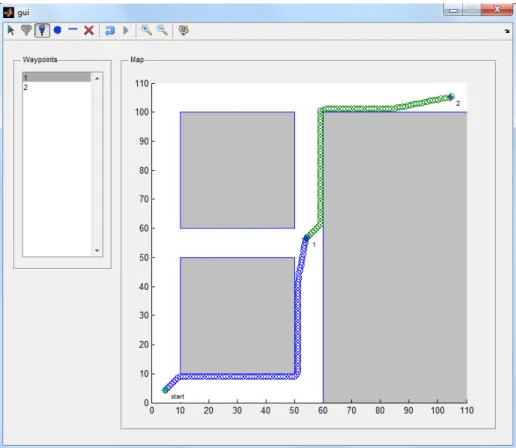
Figure 3.1 shows the GUI after a path planning simulation has been run. Two waypoints had been added to the map, but no obstacles were added. The start location is at the bottom left (green start), while the goals are at the middle and top right of the map respectively. Note that the order of goal placement is important. Path planning to each goal is done in first-in, first-out (FIFO) order. The path to each goal is computed separately, which can be seen from the map. The path color from start position to goal 1 is blue, while from goal 1 to goal 2 is green. The total elapsed time to compute both paths is 10.51s.
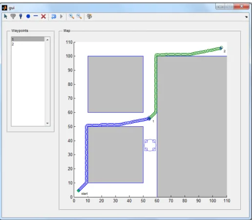
Figure 3.2 shows a path planning simulation with two waypoints and one obstacle. Instead of making a path along the east hallway from the start position, the algorithm chose to make a path along the north hallway. The obstacle was able to influence the change in path.
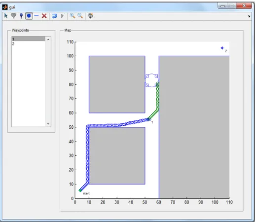
Figure 3.3 shows how the algorithm can fail to reach the goal due to local minima. The robot enters a local minimum near the obstacle and becomes trapped. There are many ways to get escape, or even prevent, falling into a local minimum. One method is to change the obstacle and goal functions in order to minimize the occurrence of local minima. Another would be to create a look-ahead algorithm, that can plan several steps ahead in
Figure 3.1: GUI depicting a path planning simulation using potential fields, where the map has two waypoints.
order get the best possible path outside of a local minimum. Another option would be to add mechanisms that would allow the robot to escape from local minima. The two latter methods would increase code complexity.
The computation time using the potential field implementation was found to be unacceptable. With local minima error correction, path planning may take even longer. Although the algorithm could be run much faster by pre-computing all the J values in the map before path planning begun, it was decided that another algorithm may be suited for the current problem, which would avoid local minima traps.
Figure 3.2: GUI depicting a path planning simulation using potential fields, where the map has two waypoints and one user-defined obstacle.
3.2 Probabilistic Road Map
As an alternative to the potential field method, the probabilistic road map (PRM) method was considered. PRM is a sampling-based algorithm that generates a set of free configurations, which could be represented as points on the map where the robot would be able to path. The algorithm can then create a path from start to goal configuration by connecting the free configurations. The algorithm starts by taking random samples from the configuration space of the map. [39]. Then, it checks whether each sample belongs to a free configuration space, which is the space where a robot can pass through, or not. Samples that are taken on or within obstacles do not belong to the free configuration space. Samples that are at a certain close distance from the obstacles may also be removed.
Figure 3.3: GUI simulation where planner was unable to reach the goal due to local minimum.
A local planner attempts to connect each configuration to its nearest neighbors. The start and goal configurations are then added to the existing connections, resulting in a graph. A path from start to goal can then be established through use of graph searching algorithms, such as Dijkstra’s algorithm.
A MATLAB simulation was created in order to test the PRM algorithm. However, a GUI was not generated because testing could be done much faster using a script.
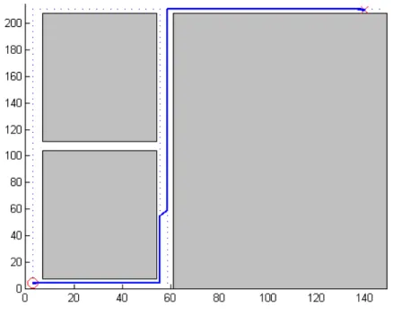
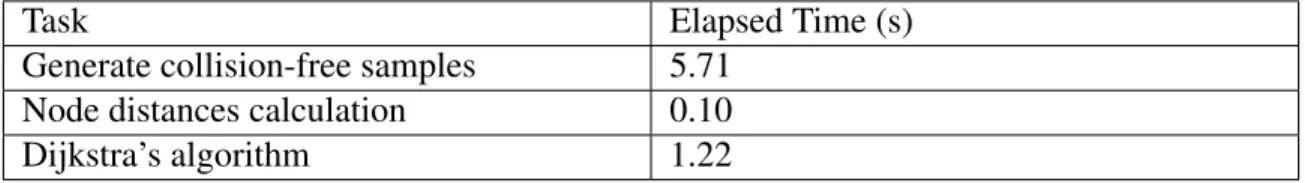
Figure 3.4 shows the path generated by the PRM algorithm. The start point is indicated by the circle in the bottom left part of the map, while the goal is the â ˘AŸX’ at the top right. The total number of samples in the configuration space is 2500. The total
number of free configurations generated for the above test is 2000, which are represented as blue dots on the map. The path is the blue line from start to goal.
Figure 3.4: PRM simulation using random samples from free configuration space.
The graph was generated by computing the distance from each free configuration to every other free configuration, and storing the distances in a 2D matrix, such that the distance specified by a row and column of matrix represent the weighted edge between one free configuration node (row index) and another free configuration node (column index). The shortest path can then be computed using Dijkstra’s algorithm.
Table 3.1 shows the performance results for the PRM algorithm. It took almost 6 seconds to generate the free configuration space. The reason is that each sample is tested to see if it falls into an obstacle or not. The sample is randomly chosen from the set of samples comprising the configuration space. The more obstacles there are in the map, the longer the check will take. The map used has three rectangular obstacles representing the walls and closed spaces of a building. Generating the distance matrix took approximately
one-tenth of a second due to the use of a MATLAB function,pdist, that can perform vector computations. Dijkstra’s algorithm took 1.22s to generate a path.
Table 3.1: Computation times of PRM using random samples in the free configuration space.
Task Elapsed Time (s)
Generate collision-free samples 5.71
Node distances calculation 0.10
Dijkstra’s algorithm 1.22
The algorithm still needed to be optimized, as the 5.71s computation time for generationg collision-free samples was unacceptable. Instead of generating the free config-urations randomly, they could be taken from a grid of points that represent the configuration space. The configuration space is overlayed with each obstacle such that points that fall within the obstacle are "zeroed out." The free configuration space is then the matrix of values containing non-zero samples (x, y).
Figure 3.5 shows the same map using the grid-based PRM algorithm. The number of free configurations is 924, which are represented by the blue dots. The dots appear denser than in the original PRM algorithm since the configuration space had 10000 samples. However, most of the samples were located within obstacles and were thus excluded from the set of free samples. Increasing the number of samples would make computation longer, but would lead to a smoother path.
Table 3.2 shows the computation times for the modified PRM algorithm. The time to generate the free configuration space is significantly lower than in the original algorithm. Since the number of free configurations is also lower, the times for both calculation of the distance matrix and Dijkstra’s algorithm had improved.
Use of a grid-based structure for generating the free configuration space greatly im-proved performance compared to the potential-field based approach. Although the current
Figure 3.5: PRM simulation use grid of samples, where samples that fall within obstacles are excluded.
Table 3.2: Computation times of PRM using fixed samples in the free configuration space.
Task Elapsed Time (s)
Generate collision-free samples 7.75e-003
Node distances calculation 2.30e-002
Dijkstra’s algorithm 2.54-001
algorithm was sufficient for planning a global path on the map, a much faster algorithm may be needed for more complex environments.
3.3 PRM-A*
The A* algorithm is a heuristic-based graph search algorithm that has properties similar to Dijkstra’s, but uses a heuristic (normally represented as a function) in order to improve the speed at which a path from start position to goal position is found. The algorithm is designed to minimize the cost generated by traversing an edge and the cost
generated by the heuristic function. For path planning, the Euclidean distance between one point (x,y) in the map to the goal was used as the heuristic.
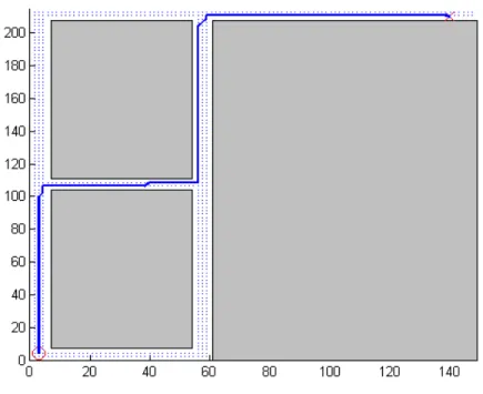
The GUI shown in Figure 3.1 was redesigned in order to work with PRM. It was modified so that the user could change the ordering of the waypoints.
Figure 3.6 shows the path generated by the PRM-A* algorithm. The start position is the green point at the lower left corner of the map, while the goal is at the top right. The simulation generated 924 free configurations like the earlier PRM algorithm.
Figure 3.6: GUI-based path planning simulation using PRM and A* algorithms.
Table 3.3 shows the performance results of the PRM-A* algorithm. It did not perform any better than the standard Dijkstra’s algorithm, given the same map, which was somewhat unexpected. The cause may have been that the A* algorithm also had to calculate a heuristic matrix of distances from each node to the goal, which contributed to the total computation time of the algorithm. There were other factors to consider, such as contention with resource on the computer, task scheduling, etc.
Table 3.3: Computation times of PRM-A*.
Task Elapsed Time (s)
Generate collision-free samples 7.76e-003
Node distances calculation 3.13e-002
Dijkstra’s algorithm 2.66-001
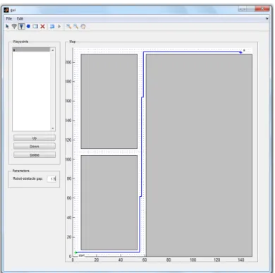
Figure 3.7 simulates a map with two goals and four user-defined obstacles. The algorithm 886 free configurations, a was able to produce a path around the obstacles, in order to reach the goal. The strength of the PRM algorithm, compared to the potential field-based path planning algorithm, is that it does not get stuck in a local minima. The PRM algorithm is a global planner, which takes plans a path by considering all of the possible configurations. The potential-field algorithm, however, is a local planner that can only plan a path within a given sensing radius.
In Table 3.4, adding more obstacles did increased the time for generating the free configuration space, however, it reduced the node distance calculation and path calculation due to having less free configuration samples.
Table 3.4: Computation times for PRM-A* path planning with two waypoints and four obstacles.
Task Elapsed Time (s)
Generate collision-free samples 9.47e-003
Node distances calculation 2.88e-002
Dijkstra’s algorithm 2.01e-001
The A* algorithm did not significantly improve the path planning computation over the Dijkstra’s algorithm. However, it could still potentially become much faster with a proper specification of the heuristic function, that takes into account more information regarding the map and the path planning task.
Based from the tests, it was found that the PRM-A* algorithm would be sufficient as a global planner for the robotic system. The potential field-based implementation per-formed considerably slower than the PRM implementation, and suffered from local minima errors. However, having a globally planned path is not enough, as the robot has to take into consideration potential changes to its surroundings. A navigation algorithm must also have local planner that would detect changes to the environment and replan a local path accordingly. Also, the actual control inputs, such as linear and angular velocity, need to be specified programmatically.
CHAPTER 4: ROBOT SYSTEM
In deciding on a robotic system to use, one was needed that would be easily pro-grammable, modular and reliable. The robot also had to allow for manual control (i.e. teleoperation). We chose the Pioneer 3-DX research robot from Adept MobileRobots.
4.1 Robot Hardware
The Pioneer 3-DX is a wheeled mobile robot that comes fully assembled, and can accommodate a number of accessories. It is intended to be used for research in an indoor environment. It has a high payload capacity (25kg), which allows it to accommodate var-ious accessories. Accessories can be connected and powered through the robot’s auxiliary serial ports. The robot platform is depicted in Figure 4.1. The robot specifications are summarized in Table 4.1.
Table 4.1: Pioneer 3-DX specifications.
Microprocessor Embedded 44.2368 MHz Renesas SH2 32-bit
RISC microprocessor with 32K RAM and 128K FLASH
Motors 2 with 500-tick encoders
Sensors 8 sonar (forward facing)
Batteries 3 hot-swappable (12VDC, 9Ah)
Ports 4 RS-232 serial ports
Body Aluminum
Wheels 2 foam filled, knobby tread, 195mm diameter, 47.4
width
Software MobileRobots’ Advanced Robot Interface for
Ap-plications (ARIA), written in C++
Length 44.5cm Width 39.3cm Height 23.7cm Clearance 6.0cm Weight 9kg Payload capacity 25kg
Although the platform comes pre-built, it still needed another computer in order to operate high level functions. The computer can be integrated into the platform in one of the following ways: connect an on-board computer (provided by Adept as an accessory) directly into the platform, connect a serial-to-WIFI bridge, which allows the robot to communicate wirelessly to a remote computer, or connect a laptop computer, which sits on top of the robot platform ("piggyback").
Although a dedicated on-board computer would be convenient, it would be an added cost to the system. Use of a serial-to-WIFI bridge would also be a convenient option, however, network reliability might be an issue, since the computer has to send "ping" messages at specific time intervals to the robot. It was decided that a laptop would be mounted on the robot platform and connected to the latter via a RS-232 serial cable. The on-board laptop specifications are summarized in Table 4.2.
Table 4.2: Laptop specifications. Name Dell Latitude E4300
CPU Intel(R) Core (TM)2 Duo CPU P9600 @ 2.53GHz
OS Ubuntu Desktop Linux 12.04 LTS
RAM 4GB
The platform can also interface with a number of accessories, such as extra sonar sensors in the rear, laser range finder, color video camera, etc. At the minimum, the robot system needed a color video camera that would be able to send video to a remote computer. In order to reduce cost and development time, the laptop’s built-in webcam was used for color video input.
The hardware setup is shown in Figure 4.2.
Figure 4.2: Pioneer 3-DX with laptop computer.
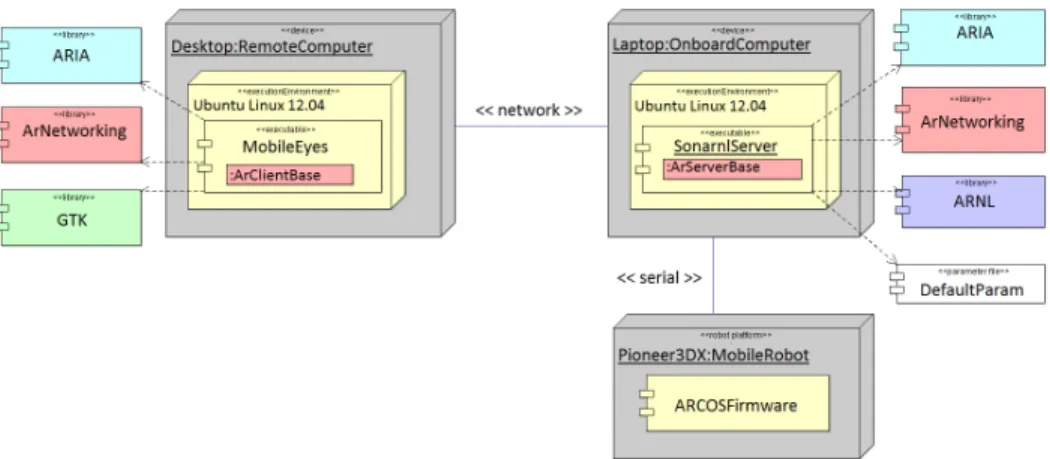
4.2 Hardware-Software Deployment
The robotic system has a three-tier control structure, consisting of the robot micro-controller, the onboard laptop and a remote computer, as seen in Figure 4.3.
The robot platform’s microcontroller provides the basic functions that control the velocity of each wheel. It also receives commands from, and sends sonar and
wheel-Figure 4.3: Robotic system hardware-software architecture.
encoder data to, the onboard computer. Communication follows a client-server relation-ship, where the robot acts as a server that can support multiple clients. The client must send periodic "keep-alive" messages to the robot server. Otherwise, the server will issue an emergency stop for safety purposes. The onboard computer can communicate to the robot server via the Advanced Robot Control and Operations Software (ARCOS) interface. AR-COS is a low-level, packet-based protocol, which is implemented in the robot’s firmware. The packets are bits of data sent directly to the robot’s serial port.
The onboard computer provides high-level functionality to the robot. The robot comes with the Advanced Robot Interface for Applications (ARIA), which is a C++ soft-ware development kit. It provides high-level functions for advanced control of the robot. Note that the onboard computer can also function as a remote computer if the robot is fitted with a serial-to-WIFI adapter.
The remote computer is used to control the robot. It communicates with the onboard computer via ArNetworking, which is the networking component of ARIA. ArNetworking provides functions for tele-operating the robot, and handles all packet-based network com-munication through TCP/IP. More detailed information about the software stack can be found in Chapter 4.3.
4.3 Proprietary Software
The Pioneer 3-DX robot platform comes with its own software development kit (SDK). Additional software is also provided for interfacing with accessory components. The following are the software packages that were used.
4.3.1 ARIA
The Advanced Robot Interface for Applications (ARIA) is an open-source software library that provides high level functions for controlling the mobile robot. It handles all packet sending and receiving between the onboard computer, which it runs on, and the robot platform. Functions are provided to allow programmatic control of the robot (i.e. move at a certain speed, in a given direction), or manual teleoperation via keyboard or joystick. ARIA also handles interfacing with robot accessories, such as pan-tilt-zoom (PTZ) camera, laser range finder (LRF) and robotic gripper. Adept provides such accessories, and the additional software needed to use them with the robot. ARIA is a native C++ library. However, interface wrappers are available for Java and Python.
4.3.2 ArNetworking
ArNetworking is the network communication component of ARIA. It uses standard TCP/IP socket communication to send control and information packets to and from the onboard computer. ArNetworking uses a client-server model, where the remote computer is the client and the robot platform’s onboard computer acts as the server. Multiple remote clients can connect to the robot server. Also, a separate remote server can be run that would allow multiple robots to communicate with multiple clients. ArNetworking allows different level of control of the robot, ranging from manual teleoperation using keyboard or joystick, to advanced navigation using waypoints (which is performed using an additional software package).
4.3.3 ARNL
The Advanced Robot Navigation and Localization (ARNL) library is a set of soft-ware packages that provide the robot with intelligent navigation and localization. Naviga-tion allows the robot to go from a start posiNaviga-tion to a goal posiNaviga-tion autonomously. Local-ization allows the robot to know where it is in the environment. LocalLocal-ization can be done using either sonar or laser sensors, if available. The navigation and localization algorithms of ARNL are closed source. However, APIs are provided to allow for a user to integrate his or her own navigation or localization algorithms.
4.3.4 SONARNL
SONARNL is the sonar localization package of ARNL. It provides a set of functions for localizing the robot using its sonar sensors.
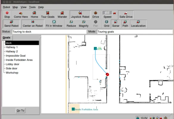
4.3.5 MobileEyes
MobileEyes is the remote teleoperation and navigation client software for Adept robots ( Figure 4.4). It has a graphical user interface (GUI) for viewing the robot remotely through a two-dimensional map, which is loaded from a file. It provides functions for controlling the robot in different ways: (1) teleoperating the robot using either a keyboard or joystick, (2) navigating the robot to a certain position in the map using a mouse and (3) commanding the robot to go to a goal position in the map (requires ARNL). It also provides a way to modify the robot’s behavioral configuration (i.e. maximum velocity, obstacle-avoidance, etc.) in real-time. If the robot is interfaced with a video camera, MobileEyes can display live video streams. This allows for non-line-of-sight teleoperation.
MobileEyes uses the ArNetworking library to communicate remotely with the robot server. However, it is closed source and only the executable is provided.
Figure 4.4: MobileEyes GUI.
4.3.6 MobileSim
MobileSim is a robot simulation software for ARIA-based robots (Figure 4.5). It allows a user to test and debug software used to control the robot. It has GUI for visualizing robot pose and its environment. It can display line data from a map file, which represents the map of the robot’s environment. MobileSim is closed source. However, it is based on the Stage simulator, which is part of the Player/Stage project, a free software tool for robot and sensor applications [40].
4.3.7 Mapper3Basic
Mapper3Basic is a software tool for creating maps, which are used by ARNL, MobileEyes and MobileSim for visualization and navigation (Figure 4.6). Maps consists of lines, points and rectangular regions. Lines represent obstacles (such as walls) in the map. Points can either be obstacles, or home and goal positions. Regions represent forbidden
Figure 4.5: MobileSim GUI.
areas of the map. Maps are loaded from and saved to a map file (filename extension .map), which is a human-readable file format. Mapper3Basic is closed source.
The more advanced map editor software for creating maps is Mapper3, which allows for point cloud-based mapping using a laser-range finder. This software is only available with the corresponding LRF accessory provided by Adept.
4.4 System Modifications
The proprietary software package had several features that performed most of the high level control operations needed in the study. However, it still lacked some features that were critical components of the study. The software needed to be modified in order to support dynamic map manipulation. Also, the software package had its own navigation algorithm, which provided both global and local planning. Although a path planning algorithm was already designed, as explained in Chapter 3, it could only determine a path to reach the goal, and not the specific inputs that the robot needed to make in order to
Figure 4.6: Mapper3Basic GUI.
reach the goal. In order to reduce development time, ARNL was used as the navigation algorithm. The algorithm’s parameters were modified in order to improve performance in the test environment.
Figure 4.7 above shows the changes made to the original hardware-software archi-tecture. The following subsections describe the changes in more detail.
4.4.1 Navigation Algorithm
After several path-planning tests conducted with the robot using ARNL for naviga-tion, it was found that the algorithm was sufficient for the study. The disadvantage is that the algorithm is closed source, and insufficient information is given regarding the design of the algorithm. However, ARNL provides an API that allowed us to modify certain parameters to change the behavior of the robot. The navigation algorithm was optimized so that the robot would perform well in a narrow hallway.