Reducing adaptive optics latency using Xeon Phi many-core processors
David Barr,
1,2‹Alastair Basden,
3Nigel Dipper
3and Noah Schwartz
11UK Astronomy Technology Centre, Royal Observatory, Blackford Hill, Midlothian, Edinburgh EH9 3HJ, UK
2Heriot-Watt University, Edinburgh Campus, Riccarton, Currie EH14 4AS, UK
3Durham University, Centre for Advanced Instrumentation, South Road, Durham DH1 3LE, UK
Accepted 2015 August 4. Received 2015 August 3; in original form 2015 July 14
A B S T R A C T
The next generation of Extremely Large Telescopes (ELTs) for astronomy will rely heavily on the performance of their adaptive optics (AO) systems. Real-time control is at the heart of the critical technologies that will enable telescopes to deliver the best possible science and will require a very significant extrapolation from current AO hardware existing for 4–10 m telescopes. Investigating novel real-time computing architectures and testing their eligibility against anticipated challenges is one of the main priorities of technology development for the ELTs. This paper investigates the suitability of the Intel Xeon Phi, which is a commer-cial off-the-shelf hardware accelerator. We focus on wavefront reconstruction performance, implementing a straightforward matrix–vector multiplication (MVM) algorithm. We present benchmarking results of the Xeon Phi on a real-time Linux platform, both as a standalone processor and integrated into an existing real-time controller (RTC). Performance of single and multiple Xeon Phis are investigated. We show that this technology has the potential of greatly reducing the mean latency and variations in execution time (jitter) of large AO systems. We present both a detailed performance analysis of the Xeon Phi for a typical E-ELT first-light instrument along with a more general approach that enables us to extend to any AO system size. We show that systematic and detailed performance analysis is an essential part of testing novel real-time control hardware to guarantee optimal science results.
Key words: instrumentation: adaptive optics.
1 I N T R O D U C T I O N
Adaptive optics (AO; Babcock1953) is a technique used to mit-igate atmospheric turbulence and partially restore the diffraction limit of optical and near-infrared ground-based astronomical tele-scopes, improving effective resolution to beyond the seeing limit. It is a critical technology for the next generation of Extremely Large Telescopes (ELTs) such as the European ELT (E-ELT) and essen-tial to achieve high-angular resolution. The main science goals of the ELTs, such as high-redshift galaxies (Puech et al.2010), stellar formation (Evans et al. 2011) or direct exoplanet imaging, pro-vide challenging requirements that current AO systems are unable to meet. To achieve these requirements new hardware needs to be investigated and characterized in the context of ELT-scale AO sys-tems.
AO systems use a corrective element, typically the surface of a deformable mirror (DM), to compensate for the phase retardation introduced by atmospheric turbulence. The required compensation is measured using one or more wavefront sensors, and must be
E-mail:[email protected]
applied within a short time-scale before the atmosphere has further evolved (i.e. a fraction of the coherence time) and is typically of the order of one millisecond. Because of the significant increase in the primary mirror size of ground-based telescopes, from the 4–10 m class telescopes of today; to the planned 30–40 m, the simple extrapolation of current real-time (RT) technology is not possible. Research and development of suitable AO technologies is required. The number of degrees of freedom of an AO system is proportional to the square of the primary mirror size and the next generation of ELTs will make computation, scaling with the fourth power of telescope diameter, extremely demanding. Real-time controllers (RTC) translating wavefront measurements into DM commands are at the heart of the AO system and therefore naturally one of the main areas of investigation. Table1shows the requirements for a selection of current and planned AO systems and stresses the high number of degrees of freedom (i.e. AO systems size) and the high update frequencies.
Wavefront reconstruction, translating measured wavefront into new DM commands, is by far the most computationally intensive algorithm that an ELT-scale RTC is required to perform. The most common wavefront reconstruction algorithm used is the matrix– vector multiplication (MVM). The DM commandsdare related to
at Heriot-Watt University on December 21, 2015
http://mnras.oxfordjournals.org/
Table 1. Selection of current and proposed AO systems with demanding computational requirements for RT control systems. SPHERE (Sauvage et al.2010), GRAAL (Paufique et al.2012), PALM3000 (Bouchez et al.
2009), GPI (Pazder et al.2012), NFIRAOS (Boyer et al.2014), HARMONI (Fusco et al.2010), EAGLE (Basden et al.2012), EPICS (V´erinaud et al.
2010).
System AO type Frequency WFS # DM actuators
SPHERE XAO 1.2 kHz 40×40 41×41 (VLT) GRAAL GLAO 1 kHz 4×(40×40) 1170 (VLT) PALM3000 XAO 2 kHz 63×63 (16×16) + (Hale) (66×66) GPI XAO 1.2 kHz 64×64 64×64 (Gemini) NFIRAOS MCAO 0.8 kHz 7×(60×60) (63×63) + (TMT) (76×76) EAGLE MOAO 0.25 kHz 11×(84×84) 20×(85×85) (E-ELT) HARMONI SCAO 0.5 kHz 84×84 85×85 (E-ELT) EPICS XAO 2–3 kHz 210×210 211×211 (E-ELT)
the slopessthrough a linear equationd=G−1s, whereG−1is the
control matrix. The computational complexity for an MVM grows asO(M2), where M is the number of degrees of freedom of the AO
system.
In recent years, several novel computationally efficient wavefront reconstruction algorithms have been developed (Poyneer, Gavel & Brase2002; Rosensteiner 2012; V´eran et al.2014). These alter-native wavefront reconstruction approaches are typically iterative and generally unable to efficiently take advantage of modern mul-ticore and many-core hardware architectures. Although the MVM typically has the largest requirements in terms of number of op-erations and memory usage compared to these other methods, it is highly parallelizable making efficient use of modern multicore architectures and widely used by the AO community. For small AO systems, CPU-based systems can typically be used. As we move towards ELT-scale systems, calculations become more and more difficult to handle with CPU alone, limited both by available mem-ory bandwidth, and raw processing power.
To achieve the required computational power, many groups have focused on GPUs (Bouchez et al.2008; Basden & Myers2012; Gratadour et al.2012; Wang & Ellerbroek2012; Wang2013; Sevin et al.2014) since they offer a potential suitable parallel environment to reduce the latency associated with the MVM calculation. Field programmable gate arrays (FPGAs) have also been used, although typically for smaller systems (Mauch et al.2014), or for only a section on the AO control loop (Zhang et al.2012) or limited to the pixel processing as part of heterogeneous RTC hardware (Fedrigo et al.2006). These hardware accelerators generally suffer from the same disadvantages: limited data transfer into and out of the acceler-ator. They lead to complex heterogeneous computing environments which give rise to complex memory structures and the movement of large quantities of data between different computational com-ponents. Accelerator architectures traditionally evolve quickly as new hardware is released, which may not be compatible with older systems, leading to lifetime and portability issues. This can cause
long development times and difficulty in maintaining and upgrading systems.
In this paper, we investigate the performance of the Intel Xeon Phi for wavefront reconstruction using the MVM algorithm. The Xeon Phi uses x86 instruction set microprocessors (same as conventional CPUs), which may help in lowering the barriers to entry compared with GPUs or FPGAs, i.e. no specialized code base or applica-tion programming interface (API) is required. The implemented code can easily be modified and upgraded, should a more perfor-mant hardware be released. The Xeon Phi also offers high-memory bandwidth to accelerate memory-bound parallel algorithms. It is however, designed for high-performance computing where the re-quirements are more focused on the mean execution time rather than on the determinism of execution time. A detailed analysis of perfor-mance in a realistic AO environment is therefore essential. Previous investigations were limited and focused on non-real-time (non-RT) Linux systems (Barr et al.2014) or on a very specific AO system (Smith et al.2014) making the generalization to other systems diffi-cult. In addition, a detailed analysis of the timings is crucial to fully understand the limitations of the hardware and extrapolate to future hardware developments. Different science cases will have differ-ent tolerances on the acceptable jitter (variation in execution time) or outliers (results significantly apart from the mean) for example, which may or may not impact science results significantly.
The rest of the paper is organized as follows. In Section 2, we give an overview of the RTC architecture including the different timings and performance metrics used for the investigation. In Section 3, we discuss the actual performance of the Xeon Phi and present detailed results of timings for a standalone system as well as integrated into an RTC system. Results are presented for a typical first-light E-ELT instrument and also for a more general approach, in order to extrap-olate to any AO system size. In Section 4, we look at the expected Xeon Phi developments and anticipate potential performance. Fi-nally, in Section 5 we draw our conclusions.
2 X E O N P H I B A S E D RT C O N T R O L 2.1 RTC architecture
The Xeon Phi is a many-core accelerator co-processor card con-nected to a processor via a PCIe bus offering a high level of pro-grammability (standardC/C++ with compiler assisted offload), high throughput, high performance per watt and low cost. The main dis-advantage, as with most accelerators, is that data communication between the host computer and the Xeon Phi will add unwanted de-lays (and jitter) to the AO loop. This leads to a heterogeneous com-puting environment which may cause issues with complex memory management and makes optimization difficult. The Xeon Phi is sim-ilar in that sense to general purpose GPUs used in high-performance computing environments. The Xeon Phi differs however from GPUs by offering x86 instruction set cores, allowing programmers to use the same design techniques as they would with CPUs. This has the potential to speed up development time and does not require spe-cialist knowledge of programming paradigms and toolkits such as
CUDAorOPENCL.
The Xeon Phi model under investigation here is the 5110P, which offers 60 cores, a clock speed of 1 GHz, 8 GB of GDDR5 memory and has a maximum theoretical memory bandwidth of 320 GB s−1.
For detailed specifications of the Xeon Phi and host computer used in this paper see TableA1in Appendix A. The Xeon Phi 5110P clock speed is slower than that of modern CPUs which can typically reach 3–4 GHz. This suggests that the Xeon Phi would be unable
at Heriot-Watt University on December 21, 2015
http://mnras.oxfordjournals.org/
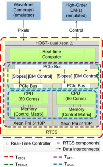
Figure 1. Hardware configuration used to benchmark the Xeon Phi. Two Xeon Phis are connected to the host computer (Xeon E5-2650) via PCIe bus. The Xeon Phi is used to accelerate the MVM. The control matrix is stored before calculations in the Xeon Phi’s memory, while wavefront slopes and DM commands vectors are transferred at each AO frame. The dashed boxes represent details of the four different times that are investigated.
to compete for performance on sequential code. Given the number of cores and the high-memory bandwidth, it has the potential to outperform current CPUs on parallel codes such as the MVM.
The aim of this investigation is to characterize and benchmark the Xeon Phi in the context of a low latency and low jitter AO control loop. We focus our study on the main task of the RTC which is to control the core AO system. We do not include additional tasks (often characterized as soft RT tasks) and do not relate our findings to a specific instrument design, preferring to adopt a more general approach. The Xeon Phi is used to accelerate MVM calculations and the rest of the AO processing tasks (such as image calibration, slope calculation and DM control laws) are performed by the host computer. The hardware configuration is shown in Fig.1. The host computer, composed of a Dual Xeon E5-2650, receives wavefront camera(s) pixels (typically a Shack–Hartmann sensor) and calcu-lates the slopes. In the studied configuration, the wavefront camera data is emulated and not physically connected to any hardware, en-suring that the system is not limited by the camera’s frame rate. The Xeon Phi then receives the slopes from the host computer through
Figure 2. Diagram showing a simplified version of the implemented pro-cess and the four different timings measured to benchmark the Xeon Phi. t1andt4are taken on the Xeon E5;t2 andt3 are taken on the Xeon Phi.
Due to the Xeon Phi and the Xeon E5 having separate unsynchronized clocks, only the total data transfer time is accessible and is calculated from
TOFFL−TCALC.
a PCIe bus and computes the command vector that is finally sent to the DM(s). Equally, no DM is physically connected to the host PC. The Xeon Phi and the Xeon E5 have a separate clock, making it difficult to accurately time data transfer and MVM calculations using the same clock. In order to produce accurate timings, we measure the difference between times on the CPU and times on the Xeon Phi, removing issues of asynchronous clocks. Throughout this paper, we will investigate four different timings to fully benchmark the performance of the Xeon Phi.
(i)TOFFL is the offload time: this represents the time from the
first data sent from the host computer to the Xeon Phi(s) to the last data received back on the host computer. This includes data transfer (i.e. slope and DM command vectors) and MVM calculation on the Xeon Phi(s).TOFFL=t4−t1(see Fig.2).
(ii) TCALCis the calculation time: this refers to the time taken for
the MVM to be calculated on the Xeon Phi (or Xeon Phis) excluding any transfer times.TCALC=t3−t2(see Fig.2).
(iii)TTRANS is the combined transfer time: this represents the
time taken for the data to be transferred in and out of the Xeon Phi. This encapsulated both the transfer of the slope vector and DM commands.TTRANS=TOFFL−TCALC(see Fig.2).
(iv)TRTCSis the RT control time: this represents the time taken for
an entire AO frame to execute. This includes the wavefront sensor (WFS) pixel processing, slope computation, the MVM calculation on the Xeon Phi(s) as well as any additional background tasks of the RT control system.
Data are taken according to the scheme presented in Fig.2. At the start of the process, we initialize and pre-load the control matrix
G−1into the Xeon Phi memory. The slope vector is then transferred
to the Xeon Phi (marked as timet1) and the MVM calculation starts
(timet2). At the end of the calculation (timet3), we transfer the
result back to the host computer (timet4) and loop back to the slope
transfer. After a statistically significant number of timings (typically 106), we free the memory and end the process. Timingst
1andt4are
taken on the host computer whereast2andt3are taken on the Xeon
Phi. This timing scheme allows us to time the overall offload time
TOFFLand MVM calculation timeTCALCseparately. From
measur-ingTOFFL and TCALC, the combined transfer time TTRANS can be
derived. Separating between transfer and calculation times offers
at Heriot-Watt University on December 21, 2015
http://mnras.oxfordjournals.org/
us the capability to locate where additional time delays are being generated.
2.2 RT Linux and Xeon Phi optimization
Modern computers are generally not RT processors and operating systems have background processes running which affect determin-ism. AO systems need a high level of determinism which non-RT operating systems are generally unable to provide. RT Linux on the other hand, gives us greater control on the order (priority) in which processes are carried out by the operating system. These processes with raised priority are able to pre-empt the lower priority tasks to give greater control and predictability in execution time. For the host computer, both a non-RT and an RT Linux kernel will be in-vestigated. An RT pre-empt 3.10 Kernel was installed on the host computer which is runningRED HAT 6.4. The RT Linux kernel was
not edited nor modified. The Xeon Phi itself is running a non-RT micro-operating system based on a Linux kernel.
To perform the MVM calculation, we investigated the perfor-mance of the IntelMATH KERNEL LIBRARY(MKL), theMAGMAlibrary (Bosma, Cannon & Playoust1997) and an MVM code developed in-house which usesOPENMPfor parallelization.MAGMAoffered much
more abstraction from the Xeon Phi architecture than the other two, which allows quick development but at the cost of reduced perfor-mance. The in-house code was optimized for certain matrix sizes and was able to outperformMKLon some specific cases. In general, MKLgave a high baseline performance for all cases. It was decided to useMKLand focus on general performance of the Xeon Phi rather
than focus on specific cases where in-house code can be tuned and optimized to obtain the best performance. UsingMKLhas the double
advantage of reaching very good performance overall but also en-suring that simple software design techniques can be used without requiring in-depth knowledge of the Xeon Phi architecture.
From a previous study (Barr et al.2014), we have shown that the Xeon Phi performs best when the problem size can fit its archi-tecture. The Xeon Phi 5110p has 60 cores, with one core reserved for input/output routines. Each core can support up to four threads, which means that when the problem size is divisible by 236 (i.e. 4×59), optimal performance is obtained. This difference in perfor-mance is likely due to the architecture and also how theMKLlibrary
handles the parallel sections of code. When the problem size fits the architecture, the library is able to split the problem evenly between all cores. When this is not the case, the library has to perform some dynamic resource handling that brings in more overhead, degrading performance. When the problem size is not divisible by 236, the control matrix is therefore padded with zeros to fit the architecture and reach the best achievable performance.
3 B E N C H M A R K I N G T H E X E O N P H I
In this section, we present a detailed analysis of the performance of the Xeon Phi. It is important here to note that different science cases will put different constraints on AO system requirements. Some (e.g. direct exoplanet imaging) will require very high image contrasts. Achieving these contrast levels will require very low and stable AO loop latencies. Other science drivers (e.g. high-redshift galaxies, stellar formation) will have somewhat lower requirements, in particular on stability. The variation in latency (i.e. stability of the system), often called jitter, will be evaluated in this paper as the
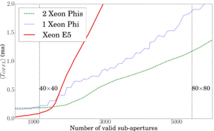
Figure 3. Comparison of the mean offload timeTOFFLas a function of the
numberMof valid sub-apertures using 104samples. Red: Xeon E5; Blue:
single Xeon Phi; Green: two Xeon Phis. Results obtained using an RT Linux kernel. The dashed vertical lines represent the approximate size of an AO system in total number of sub-apertures.
standard deviation1of the measured timest. Outliers (i.e. frames
taking significantly longer to complete than the mean execution time) are also crucially important. In order to refine the analysis, the full distribution of the measured timings will be given, along with mean, jitter, minimum, maximum and percentiles of timings completed before a given time.
In order to stay as general as possible, and not tie this study to any specific instrument design, the AO system size (M) will be defined as the total number of wavefront measurement points (typically the number of valid sub-apertures of a Shack–Hartmann wavefront sensor). The slope vector size is 2M as it contains the slopes in
XandYdirections for each valid sub-aperture. In a typical single conjugate AO (SCAO) system, the number of valid sub-apertures is approximately equal to the number of DM actuators and so the DM command vector will be approximately half the size of the slope vector. The control matrix (G−1) will therefore be of dimension
M×2M unless explicitly stated otherwise.
After testing the Xeon Phi as a function of AO system size M, we focus our attention on a typical first-light SCAO E-ELT instru-ment with approximately 80×80 sub-apertures. For such a system, the control matrix contains 9440 rows and 5428 columns (taking into account an aperture with central obscuration), which in turns corresponds to a memory size of≈205 MB, using 4 byte (32 bit) single-precision floating-point numbers. Typically slope data are only accurate to 16 bits, allowing 4-byte floats to provide sufficient accuracy for non-high-contrast AO systems (Basden, Myers & But-terley2010a). Tests are run both on a non-RT Linux kernel and an RT Linux kernel system using one and two Xeon Phis, allowing us to investigate scaling with number of co-processors. Finally, we will show that the generality of our conclusions will not be lost by exploring a specific system size.
3.1 Influence of AO system size
3.1.1 Offload time as a function of AO system size
Fig. 3shows the comparison of mean offload time TOFFL (i.e.
including MVM calculation and data transfer) for the Xeon E5
1 σ = 1 N N
i=1(ti−μ)2, where the meanμ=N1 Ni=1ti The mea-sured distributions are not normal distributions and classical interpretation of the standard deviation is not possible.
at Heriot-Watt University on December 21, 2015
http://mnras.oxfordjournals.org/
Figure 4. Comparison of the mean offload timeTOFFLas a function of the
numberMof valid sub-apertures using 104samples. This figure is a zoom
of data found in Fig.3for better readability.
Figure 5. Variation in offload timeTOFFLusing a single Xeon Phi with
the host running an RT Linux Kernel. Only multiples of 236 are shown as they provide best performance. A logarithmic colour lookup table is use to visualize both peaks and tails of the distributions. The red line represents the mean, purple representsP99 per cent, yellow representsP99.99 per centand
the white line represents the maximum time measured.
alone, a single Xeon Phi and two Xeon Phis used as accelerators as a function of AO size. For the smaller AO systems where the number of valid sub-apertures is less than approximatelyM<1500 (such as for a 40×40 SCAO system) the Xeon E5 clearly outperforms the Xeon Phi(s). This is due to the need to transfer data (i.e. slope and DM command vectors) over the PCIe bus. Once the number of valid sub-apertures becomes larger, the Xeon Phis provide lower mean latencies (this clearly visible in Fig.4, a zoomed version of Fig.3for the range 0–6000 sub-apertures).
As expected, for large numbers of valid sub-aperturesTOFFL
grows asO(M2) for all devices, dominated by computation time.
When two Xeon Phis are used,TOFFLcan be further reduced; the
difference is more clearly visible for large AO systems.
As stated previously, the mean execution time is insufficient to fully characterize the AO RTC. Fig. 5shows the distribution of offload timesTOFFLas a function of AO system size, using an RT
Linux kernel, and measuring TOFFL over 106 iterations for each
system size. Only matrix size multiples of 236 are shown because mean and variation in execution time are both increased for non-multiples. It can be seen that not only all system sizes have a similar bimodal distribution but the mean, the position of peaks and
Figure 6. Increase of offload timeTOFFL as the number of elements of
the control matrix is increased fromM×2Mto a square with 2M×2M elements (the control matrix has (M+n)×(2M) elements, where 0≤n≤M and 2M=9440). Data calculated using 106samples. A logarithmic colour
lookup table is use to visualize both peaks and tails of the distributions. the different percentiles calculated (percentile of offload times that are completed by the given time) all follow a similar trend. Only the maximum offload time is shown to be somewhat irregular; we believe this is because of the limited number of samples used (i.e. 106) to calculate the distribution. From Fig.5, we can legitimately
say that studying a specific AO system size in detail will not remove the generality of the analysis as results can be scaled to match the desired system size. Results obtained with two Xeon Phis (data not shown here) show the same scalability.
3.1.2 Influence of shape of the control matrix
So far we have discussed the performance of the Xeon Phi in the context of SCAO systems, where the number of DM actuators is approximately equal to the number of sub-apertures and where we have assumed that the control matrix shape isM ×2M. In this section, we investigate how the shape of the control matrix affects the general performance of the MVM calculation. Fig.6 shows the additional offload timeTOFFL taken as we increase the
control matrix size fromM×2Mto a square with 2M×2M ele-ments (i.e. the control matrix has (M+n)×(2M) elements, where 0≤n≤M). The baseline system (i.e. wheren=0) is equivalent to an 80×80 AO system with 2M= 9440. As we have stated previously, all dimensions of the matrix are a multiple of 236 to maximize performance (explaining the steps in performance for ev-ery increase ofnby 236). We see that the time increase is linear (i.e. increases linearly with the number of additional control matrix elements) and the overall shape of the distribution remains identical for all system sizes (double peak with a tail). It is important to stress at this point that using Fig.5in conjunction with Fig.6enables us to estimate the performance of a single Xeon Phi for most AO system sizes, regardless of the size or shape of its control matrix.
3.1.3 Memory bandwidth
When performing the wavefront reconstruction in an AO RTC using an MVM algorithm, the input vector is updated at every iteration (typically from hundreds to thousands of times per second), while the control matrix will remain constant for periods of time between tens of seconds to several hours. However, for large AO systems the matrix is too large to be stored in cache, and so must be read from
at Heriot-Watt University on December 21, 2015
http://mnras.oxfordjournals.org/
Figure 7. Memory bandwidth for a single Xeon Phi performing an MVM as a function of number of valid sub-apertures. This includes the data transfer time across the PCIe bus. The calculation only memory bandwidth will be slightly higher.
memory at each iteration. Therefore, memory bandwidth becomes a performance limiting factor. CPU-based systems typically have large banks of DDR3 memory which are relatively slow. The Xeon Phi has access to faster GDDR5 and has a maximum theoretical memory bandwidth of 320 GB s−1. In practice, the Xeon Phi appears
to have a read memory bandwidth of 164 GB s−1and a write memory
bandwidth of 76 GB s−1(Fang et al.2014).
Here, we have measured computation time for the MVM oper-ation, and use this information to calculate the achieved memory bandwidth. Fig.7shows memory bandwidth as a function of AO size (and the control matrix size stored in memory) for a single Xeon Phi calculated from the offload timeTOFFL.TOFFLincludes the TCALCandTTRANSso the memory bandwidth of just the Xeon
Phi processor will be slightly higher. For large AO systems, the calculation time is limited by the memory bandwidth, which peaks at about 160 GB s−1, in agreement with Fang et al. (2014). We note
that for smaller systems, memory bandwidth is not the performance limiting factor; however, these systems are not of interest here since we are concentrating on larger systems.
When the control matrix is larger than the Xeon Phi L2 cache (30 MB), we see a drop in memory bandwidth due to the processor having to transfer all or part of the control matrix from the slower GDDR5 memory. As we increase the size of the control matrix, the processors have to make more and more calls to the slower GDDR5 memory. This continues until the control matrix reaches around 800 MB where the memory bandwidth levels around 160 GB s−1. At this
point, the control matrix is significantly larger than the L2 cache and most memory access is with the GDDR5 memory. The MVM like other BLAS-12or BLAS-23routines is memory bandwidth limited.
To confirm the achievable memory bandwidth, we used the industry standard STREAM memory benchmarking (McCalpin 1991-2007) on both the Xeon E5 and the Xeon Phi. We compared the memory bandwidth to a TRIAD4test which is the STREAM
benchmarking scheme most closely resembling an MVM operation. The Xeon E5 achieved a peak memory bandwidth of 63.7 GB s−1
and the Xeon Phi of 166.5 GB s−1. Other groups have published
similar results (Fang et al.2014).
2Vector–vector operations. 3Matrix–vector operations.
4The Triad test involves the addition of two vectors (bandc) one vector
multiplied by a scaling factor (q)ai=bi+q×ci.
Table 2. A comparison of advertized and achieved memory bandwidths for Dual Xeon E5-2650, NVidia K40 GPU and Xeon Phi 5110p.
Dual Xeon E5-2650 NVidia K40 Xeon Phi Advertized Max. GB s−1 2×51.20 288 320
STREAM GB s−1 63.7 229 166.5
Percentage 62.2 per cent 79.5 per cent 52.03
Figure 8. Number of FLOPS achieved during MVM for a dual Xeon E5-2650, one Xeon Phi and two Xeon Phis.
Table2compares the advertized (theoretical), achieved memory bandwidths using STREAM as well as the percentage of the adver-tized that was attained. The results are shown for the Dual Xeon E5-2650, the Xeon Phi 5110p as well as the NVidia K40 GPU (Reguly et al.2014, a GPU released at around the same time as the Xeon Phi, which enables a direct comparison between hardware of the same generation). It can be seen that although the Xeon Phi has a higher theoretical maximum, the GPU can achieve a higher percentage of the advertized bandwidth than either the Xeon E5 or the Xeon Phi.
3.1.4 Floating-point operations per seconds
Floating-point operations per seconds (FLOPS) is a common met-ric that is frequently used to assess and compare performance of computing hardware. It can be calculated theoretically from equation (1),
FLOPS cycle ×
cores
socket×#sockets×clock. (1)
The Xeon Phi is advertized to be able to reach 1.011 TFLOPS. This value is far larger than we could expect to reach with the MVM or any other BLAS-1 or BLAS-2 operations due to the memory bandwidth limitations.
Fig.8shows the number of FLOPS that the Xeon E5-2650, Xeon Phi and two Xeon Phis have achieved when performing the MVM algorithm as function of AO system size. A peak in performance is seen for the Xeon E5-2650 below 2000 sub-apertures, which is when the matrix no longer fits in cache memory of the CPU. Curves for the single and dual Xeon Phi follow that of the memory bandwidth.
Table3shows the number of FLOPS that the Xeon E5-2650, Xeon Phi and two Xeon Phis have achieved when performing the MVM algorithm for a selection of AO system sizes. It can be seen that the performance of the Xeon Phi is much lower than the adver-tized FLOPS. This is what is expected due to the memory bandwidth attainable on the Xeon Phi. We see that using a second Xeon Phi
at Heriot-Watt University on December 21, 2015
http://mnras.oxfordjournals.org/
Table 3. Comparison of FLOPS for Dual Xeon E5-2650, single Xeon Phi and a Dual Xeon Phi system. Max is the maximum GFLOPS achieved across entire tested range, 0–14 000 sub-apertures.
GFLOPS of 40×40 80×80 120×120 Max
Xeon E5-2650 58.7 17.3 17.3 58.7
One Xeon Phi 25.2 62.7 76.9 79.4
Two Xeon Phis 29.0 100.3 136.9 141.5
Figure 9. Relative performance of using two Xeon Phis instead of one: TOFFL2Phis/TOFFL1Phias a function of system size. The dashed vertical
lines represent the approximate size of an AO system in total number of sub-apertures.
allows for a doubling in the number of FLOPS for large system, which is what would be expected.
3.1.5 Multiple Xeon Phi speedup
An MVM operation is highly parallelizable, and therefore easy to split between multiple Xeon Phi accelerators. Using a second Xeon Phi to complete the MVM doubles the available compute power and memory bandwidth. However, synchronization between the two processes makes achieving a speedup of×2 difficult. Fig.9 shows the offload time speedup that can be achieved by using two Xeon Phis instead of one. For small systems, using two Xeon Phis is actually slower than just relying on one, due to overheads. As the control matrix size increases, the speedup gradually rises to reach a plateau (starting from about a 120×120 AO system) of approximately 1.8. Using a second Xeon Phi to complete the MVM allows us to have twice the cache memory (60 MB). This explains the first performance peak on Fig.9while a single Xeon Phi would have to access the slower GDDR5 memory, the two Xeon Phis are able to fit the control matrix within the available combined cache memory. A single computer can contain up to eight Xeon Phis, as long as it has a sufficient number of PCIe bus lanes. Data can be transferred simultaneously to multiple Xeon Phis as long as there are unused lanes available.
3.2 Detailed analysis of temporal behaviour
As we have seen in the previous section, mean offload time does not enable us to fully characterize where the different latencies in using the Xeon Phi are coming from and how they affect the calculation speed. Access to the full distribution of computation times is therefore necessary. In addition, we have checked that studying a specific AO system size will not remove the generality
Figure 10. Histogram comparing the offload timeTOFFLfor a 80×80
sub-aperture system calculated using 106samples.T
OFFLencapsulates both
calculation time and transfer time. Blue: single Xeon Phi on a RT Linux host; Red: single Xeon Phi on non-RT Linux; Green: two Xeon Phi on RT Linux kernel. Inset shows data from 2.5 to 15 ms with the number of frames ranging from 0–12 (showing outliers more clearly).
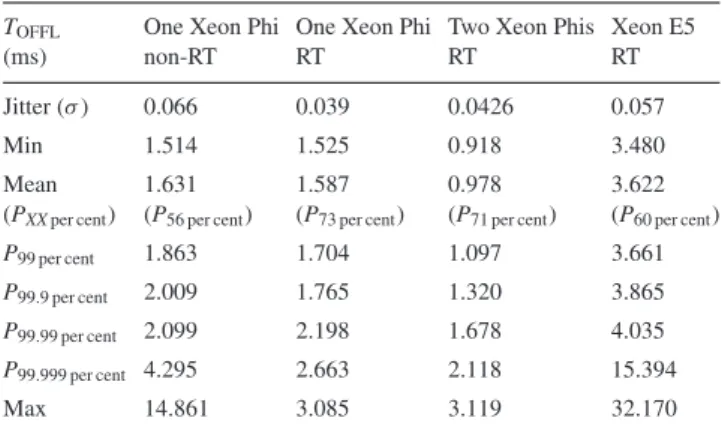
Table 4. Offload timesTOFFLcorresponding to Fig.10.PNper centis theNth
percentile of offload times that are completed by the given time. All times given in milliseconds.
TOFFL One Xeon Phi One Xeon Phi Two Xeon Phis Xeon E5
(ms) non-RT RT RT RT
Jitter (σ) 0.066 0.039 0.0426 0.057
Min 1.514 1.525 0.918 3.480
Mean 1.631 1.587 0.978 3.622
(PXXper cent) (P56 per cent) (P73 per cent) (P71 per cent) (P60 per cent)
P99 per cent 1.863 1.704 1.097 3.661
P99.9 per cent 2.009 1.765 1.320 3.865
P99.99 per cent 2.099 2.198 1.678 4.035
P99.999 per cent 4.295 2.663 2.118 15.394
Max 14.861 3.085 3.119 32.170
of the analysis as results can be scaled to match the desired system size. In this section, we analyse detailed results for a typical E-ELT first-light AO instrument with 80×80 sub-apertures (using a 9440×5428 element control matrix, or 205 MB).
3.2.1 Variability in offload time:TOFFL
Fig.10showsTOFFLfor three tested configurations (i.e. one Xeon
Phi used with a non-RT Linux host, and one and two Xeon Phi used with an RT Linux host). For each configuration, 106
measure-ments were taken. Table4shows more details on the offload time, analysing the distributions in terms of minimum and maximum values, jitter, mean and percentiles. The percentilesPXXper centare
defined as the time by whichXXper cent of the samples are com-pleted. In other wordsP99.99 per centrepresents a 1 in 10 000 event.
Also shown in Table4are the results of the Xeon E5 completing the same MVM calculation on an RT Linux system.
Fig.10distribution is double peaked with a long tail due to out-liers; Smith et al. (2014) have published a similar distribution. The shape of this distribution causes the mean not to sit atP50 per cent(the
median value) but atP56 per cent for non-RT Linux and atP73 per cent
for RT. Using an RT Linux does not appear to greatly decrease the mean latency when compared to the non-RT Linux. It seems how-ever to reduce the majority of the extreme outliers and significantly
at Heriot-Watt University on December 21, 2015
http://mnras.oxfordjournals.org/
Figure 11. Histogram comparing the calculation timeTCALCfor a 80×80
sub-aperture system calculated using 106samples.T
CALCexcludes the
trans-fer time. Blue: single Xeon Phi post-firmware update; Red: single Xeon Phi pre-firmware update. Inset shows data from 1.8 to 2.5 ms with the number of frames ranging from 0–12 (showing outliers more clearly).
lower the jitter (which is defined as the deviationσ) from 0.066 to 0.039 ms. As expected, two Xeon Phis on an RT Linux system produces the lowest latency;TOFFLis about 1.6 times less than on
a single Xeon Phi. However, jitter is increased. This is not entirely surprising as to complete the MVM, both Xeon Phis need to have finished their calculation. This means that for a given frame, jitter is introduced by the worst-performing Xeon Phi. The outliers occur so infrequently thatTOFFLis unaffected.
Even by using two Xeon Phis, the number of outliers measured may still be a concern for certain AO configurations. With 1 outlier every 10 000 frames (i.e.P99.99 per cent) for a system running at 500 Hz
this will occur 180 times over the course of an hour observation. To identify where these outliers are arising and see if they can be reduced, we investigate in the following sections the split ofTOFFL
into its componentTCALCandTTRANS.
3.2.2 Variability in calculation time:TCALC
Since the MVM is only calculated on the Xeon Phi, it does not directly interact with the operating system running on the host com-puter. We do not expect to see any changes in the distribution of the MVM calculation timeTCALCon RT or non-RT systems.5However
compiling the Xeon Phi drivers to be compatible with an RT Linux meant upgrading the Manycore Platform Software Stack (MPSS) to the latest version at the time of writing.6This update brought
up-dated versions of Flash and System Management Controller (SMC). MPSS and the updates are only partially open source. This suggests that issues arising from updates may be solvable by editing these sections of the source code without the manufacturer’s support. However, some sections are closed source which may make user modifications more difficult.
Fig.11shows the results for pre-updated Flash/SMC and after the update was applied. It seems to suggest that the update caused a reduction in performance and larger variations in timings. The variation in calculation timeTCALCis probably due to the fact that
the Xeon Phi is running a non-RT micro-Linux which results in some large outliers (V´eran et al.2014). In Table5, we see that the update slightly reduces both mean calculation times and jitter. It is
5This was shown to be true by going back to a non-RT system after update. 6MPSS 3.4 (Flash 390-2; SMC: 1.16) from Linux Gold Update 3 (Build:
2.1.6720-13; Flash:386-2; SMC:1.14)).
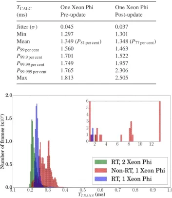
Table 5. Calculation timesTCALCcorresponding to Fig.11.
PNper centis theNth percentile of MVM calculation times
that are completed by the given time. All times given in milliseconds.
TCALC One Xeon Phi One Xeon Phi
(ms) Pre-update Post-update
Jitter (σ) 0.045 0.037
Min 1.297 1.301
Mean 1.349 (P81 per cent) 1.348 (P77 per cent)
P99 per cent 1.560 1.463
P99.9 per cent 1.701 1.522
P99.99 per cent 1.749 1.957
P99.999 per cent 1.765 2.306
Max 1.813 2.505
Figure 12. Histogram comparing the transfer timeTTRANSfor a 80×80
sub-aperture system calculated using 106samples.TTRANSis the combined
time for transferring data in and out of the Xeon Phi. Blue: single Xeon Phi on an RT Linux kernel; Red: single Xeon Phi on non-RT Linux. Inset shows data from 1 to 13 ms with the number of frames ranging from 0–6 (showing outliers more clearly).
not untilP99.99 per centthat we see that the outliers become worse after
the update. This is a problem for the performance of the system, it also highlights a larger problem of using hardware accelerators such as the Xeon Phi or GPUs. Neither of these technologies are designed for RT control systems, and any AO RTC system based on hardware accelerators is tied to the development and direction the company developing them decides on. An upgrade that is beneficial to high performance computing (HPC) or gaming community may degrade AO RTC performance. As a result, and since mean and jitter cannot fully characterize hardware for AO applications, it is necessary to analyse the full distribution of frame computation times when comparing or upgrading hardware.
3.2.3 Variability in data transfer:TTRANS
The larger outliers seen inTOFFLwere not seen inTCALC, suggesting
that the main cause lies in transfer timeTTRANS. Fig.12 shows
the distribution of data transfer timings for both a host computer running non-RT and RT Linux system. Table6shows the detailed results for the data transfer. It demonstrates that the large outliers seen in the non-RTTOFFLare indeed caused by the transfer of data
between the host computer and the accelerator. We see that moving to a RT Linux has reduced the outliers bringing the maximum values from 13.507 ms down to 1.747 ms, a large reduction. It has also suppressed most of the outliers, but not all, and reduced jitter from 0.048 to 0.014 ms. On average, the system spends 15 per cent of
at Heriot-Watt University on December 21, 2015
http://mnras.oxfordjournals.org/
Table 6. Transfer timesTTRANScorresponding to Fig.12.
PNper centis theNth percentile of transfer times that are
com-pleted by the given time. All times given in milliseconds. TTRANS One Xeon Phi One Xeon Phi
(ms) Non-RT RT
Jitter (σ) 0.048 0.014
Min 0.196 0.204
Mean 0.283 (P81 per cent) 0.239 (P77 per cent)
P99 per cent 0.359 0.313
P99.9 per cent 0.592 0.344
P99.99 per cent 0.752 0.399
P99.999 per cent 2.957 0.647
Max 13.507 1.747
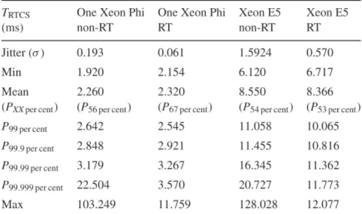
Table 7. Entire AO frame processing timesTRTCScorresponding to Fig.13.
PNper centis theNth percentile of entire AO frame processing times that are
completed by the given time. All times given in milliseconds.
TRTCS One Xeon Phi One Xeon Phi Xeon E5 Xeon E5
(ms) non-RT RT non-RT RT
Jitter (σ) 0.193 0.061 1.5924 0.570
Min 1.920 2.154 6.120 6.717
Mean 2.260 2.320 8.550 8.366
(PXXper cent) (P56 per cent) (P67 per cent) (P54 per cent) (P53 per cent)
P99 per cent 2.642 2.545 11.058 10.065
P99.9 per cent 2.848 2.921 11.455 10.816
P99.99 per cent 3.179 3.267 16.345 11.362
P99.999 per cent 22.504 3.570 20.727 11.773
Max 103.249 11.759 128.028 12.077
the total offload time transferring data in and out of the Xeon Phi. When adding a second Xeon Phi (data not shown here), the transfer timeTTRANSis not reduced by much, even though only half the data
needs to be transferred to each Xeon Phi. This transfer happens simultaneously but due to the overheads involved,TTRANScannot
be reduced by a significant amount.
In order to increase robustness, a method for reducing transfer (and calculation) time variability could be devised by using two Xeon Phis performing identical calculations. When the fastest Xeon Phi has finished its calculations, the other is interrupted to be ready to receive slopes from the next frame. There is no simple functionality to interrupt a call to theMKLlibrary running on the Xeon Phi once
it has started or to stop the data transfer. This issue has not been investigated in this paper, and it is believed that the next Xeon Phi generation (standalone CPU with no data transfer, see Section 4) will be able to run an RT Linux system therefore removing almost entirely these very high latency events.
3.2.4 Integration of Xeon Phi into an AO RTC software:TRTCS We have shown that the Xeon Phi is able to reduce MVM calculation time for large systems over that of modern CPUs, such as the Xeon E5. In this section, we integrate the Xeon Phi into a complete AO RT control software. We chose to integrate the Xeon Phi into Durham Adaptive optics Real-time Controller (Basden et al.2010b), which is currently being used on the William Herschel Telescope for the CANARY AO demonstrator. In this section, we run an end-to-end simulation of an AO RTC system using simulated wavefront sensor data. The measured time TRTCS includes WFS pixel processing,
Figure 13. Histogram comparing the entire AO frame processingTRTCS
for a 80×80 sub-aperture system calculated using 106 samples.T RTCS
encapsulates MVM calculation time, transfer time, pixel processing, slope computation and any overhead of running the RTC system. Blue: single Xeon Phi on RT Linux kernel. Red: single Xeon Phi on a non-RT Linux. Inset shows data from 4 to 103 ms with number of frames ranging from 0–14 (showing outliers more clearly).
slope calculation, the MVM calculation on the Xeon Phi as well as additional background tasks of the RTC system.
Only a single thread is able to transfer data to the Xeon Phi at one time. The transfer step has a larger amount of overhead when compared the data transfer size. This overhead means that if we pipeline the AO control loop and transfer groups of slopes to the Xeon Phi and split the MVM into multiple smaller MVMs the overallTRTCS is increased. Although pipelining the MVM is
possible, it was decided here to perform a single MVM per frame, when all slopes have been calculated. For the next generation of the Xeon Phi, where there is no transfer step, pipelining will be more appropriate.
Fig.13shows the comparison betweenTRTCSrunning both
non-RT and non-RT Linux using a Xeon Phi to accelerate the MVM. Table7 shows more detailed results of the RTC processing time, analysing the distributions in terms of minimum and maximum values, jitter, mean and percentiles. It also shows the results for the RTCS running on the Xeon E5 only, without Xeon Phi acceleration. Offloading the MVM to the Xeon Phi and running on an RT Linux system brings the jitter down (i.e. narrower distribution) and reduces the number of outliers, although they are not completely eliminated. The jitter of the whole RTC is reduced from 0.193 ms for a non-RT Linux down to 0.061 ms for an RT Linux, a sizeable reduction. The outliers appear to be far worse than for the standalone tests; this is likely to be due to the fact that the CPU is now stressed with other tasks such as WFS data processing and thread synchronization. As expected, moving to an RT kernel has made the maximum value drop, from 103 to 11.8 ms. The minimum and mean values have however increased slightly on the RT system; this is likely due to how the internals of the RT kernel work allowing a process with raised priority to pre-empt other processes. RT Linux systems do not optimize for overall performance, they optimize for reliability and predictability.
Although this performance would not be sufficient for typical first-light E-ELT instruments (e.g. mean frame time of 2.3 ms), we have demonstrated in this section that incorporating the Xeon Phi into an existing AO RT control software can be done efficiently without investing a significant amount of time and effort and has the potential to improve the RTC performance.
at Heriot-Watt University on December 21, 2015
http://mnras.oxfordjournals.org/
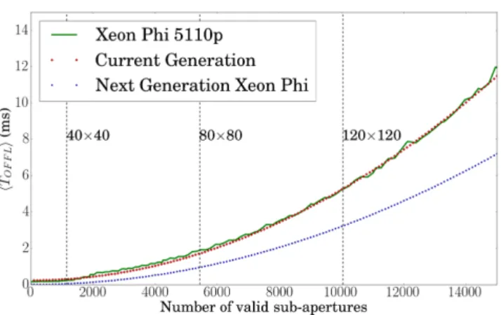
Figure 14. Comparison of mean MVM execution time between the current Xeon Phi (5110P) and the predicted next generation. These projections are based on the specifications found in TableA1in the appendix. Green: current version; Red: current version based on predictive model; Blue: next generation estimation based on same model.
4 P R O S P E C T I V E E VO L U T I O N O F T H E X E O N P H I
The next generation of Xeon Phi has been announced and will likely come in two variations. The first version is the same as the current version: an accelerator card connecting to a host computer over the PCIe bus. The second variation will be available as a standalone CPU and is the variation that seems to offer the most potential for AO applications. As a standalone CPU it will remove the need to transfer data to the host and back, which causes the large outliers and introduces additional latency. It is expected to support the standard operating systems, including an RT Linux kernel, further removing the amount of calculation jitter.
Some specifications have been disclosed by Intel on the next gen-eration of Xeon Phis, codenamed ‘Knights Landing’ (Intel2014), and can be found in TableA1. The next Xeon Phi cores will be based on the Intel Atom CPUs which have a cache of 512 kB each and the total number of cores will be 60+. The clock speed is expected to be ≈1–1.5 GHz which is slower than modern CPUs, making the Xeon Phi likely to suffer the same performance problem when running serial code. The type of CPU used suggests that the L2 cache of the entire system will be 30–35 MB. The size of control matrix for ELT first light instruments is however considerably larger than this (at least 205 MB) and we can safely assume that the MVM will still be memory bandwidth limited. The specifications suggest a memory bandwidth of over 500 GB s−1. In our tests, we found
that the actual achievable memory bandwidth was close to half the stated theoretical maximum; we are likely to be able to achieve a memory bandwidth of≈250 GB s−1.
From these specifications, we can estimate the average perfor-mance (see Fig.14) of the current Xeon Phi and how the next gen-eration might scale as a function of system size. The mean perfor-mance of the next generation rivals that of two Xeon Phis of current generation. For an 80×80 systemTOFFL = TCALC =0.86 ms
(1.587 ms for the current generation), which is compatible with the 500 Hz frame rate of first-light E-ELT instruments. The large increase in performance is mainly due to the removal of the data transfer step and to higher memory bandwidth. Jitter and outliers are harder to predict. It is reasonable however, to assume that the distribution curve forTCALCwill be similar to that of the current
generation and that running an RT Linux kernel on the Xeon Phi
will further reduce both jitter and the number of outliers. The next Xeon Phi generation, being a standalone CPU, has the potential to offer the performance benefits of the current hardware accelerators (e.g. Xeon Phi, GPUs) while removing the main disadvantages of this technology: the transfer of data.
In this paper, we have only considered the use of a unique con-trol matrix throughout the operation of the AO system. In reality, the control matrix will need to be updated as the observation con-dition changes; for the E-ELT this is likely to be of the order of minutes. The Xeon Phi offers asynchronous transfer of data which should allow for the matrix to be updated during calculations. It is likely however to interfere with performance. The next genera-tion of Xeon Phi (standalone CPU) should mitigate the impact of control matrix swapping by allowing a new matrix to be uploaded without transferring it over the PCIe bus. Although maybe small, the impact of having the MVM coefficients not in L3 cache needs to be investigated. Transferring a updated control matrix into memory will reduce the memory bandwidth for the MVM calculation. To lessen the impact of this on performance, the updated matrix can be uploaded over several iterations.
5 C O N C L U S I O N S
In this paper, we have presented a detailed study of the Xeon Phi, a many-core processor, used as compute accelerator for AO RT applications. We investigated performance for the most compute intense part of the RTC: the wavefront reconstruction. Our exam-ination focused on the MVM algorithm, the most commonly used and the most parallelizable of wavefront reconstruction algorithms. This enables us to take full advantage of the high number of cores of the Xeon Phi. We described how AO system size and the number of Xeon Phis impact performance and investigated the main con-tributors to the time delay splitting between data transfer time and MVM calculation. Finally, we discussed the implementation ease and overall performance of integrating the Xeon Phi into a complete RTC software.
We demonstrated that performance changes gradually over the whole range of control matrix sizes studied, and that performance for a specific AO system can easily be assessed by scaling. We be-lieve that this paper can serve as a guideline for estimating MVM performance for any AO system size using a single or multiple Xeon Phis. A more detailed analysis also showed that mean exe-cution time is rarely sufficient to fully qualify novel hardware (or when updating firmware) in RT applications and that the actual dis-tribution of execution times needs to be analysed in detail. To make the comparison between potential RTC hardware more tractable, we decided to present results in terms of minimum, maximum, mean, deviation (jitter) and percentile of execution time.
Using the Xeon Phi enables a clear improvement in MVM mean calculation time, whether tested as a standalone system or fully integrated into the RTC software. We have shown that moving the host from a non-RT to an RT Linux system can naturally reduce the number and extent of outliers, as well as reduce mean offload times. For a typical 80×80 E-ELT first-light SCAO system, mean offload timeTOFFL ≈1.587 ms and 99.999 per cent of the offloads
are finished within≈2.663 ms. However, a number of outliers are still present (most likely due to the fact that the Xeon Phi is running a non-RT micro-Linux) probably making the current generation of this technology only suitable for some AO RT applications [e.g. ground layer adaptive optics (GLAO), multi object adaptive optics (MOAO)] but unsuitable for others [e.g. eXtreme adaptive optics (XAO)].
at Heriot-Watt University on December 21, 2015
http://mnras.oxfordjournals.org/
Sharing calculations between two Xeon Phis allows us to fur-ther reduce mean offload time TOFFL. The maximum speedup
between one and two Xeon Phis plateaus at around 1.8 for large systems, and the speedup for a typical 80×80 E-ELT first-light SCAO system reaches 1.6. In this configuration, the mean offload timeTOFFL ≈0.978 ms and 99.999 per cent of the offloads are
finished within ≈2.118 ms. This shows the scalability of a sys-tem using multiple Xeon Phis, and it is reasonable to assume that adding more Xeon Phis would further reduce the latency in a similar way.
The Xeon Phi is designed to be used within supercomputers, and the HPC community is generally more focused on data throughput rather than on time-critical processes. We have found that the vari-ability in execution time (increased jitter and outliers) can increase after firmware updates. Using the Xeon Phi as an offload card turns a homogeneous CPU system into a heterogeneous computing en-vironment, which is more complex to programme and to balance work loads efficiently. On the other hand, the theoretical memory bandwidth of the Xeon Phi is very high, which is essential for a bandwidth limited problem such as the MVM. We have shown that about 50 per cent of the theoretical memory bandwidth is achiev-able, in line with other findings (Fang et al.2014). In addition, we have shown that the achievable memory bandwidth can offer a good estimate for the mean performance of the Xeon Phi calculating the MVM, and that most of the outliers come from transferring data in and out of the Xeon Phi. The expected next Xeon Phi generation has great potential in being suitable for AO, being an integrated CPU, eliminating the need to transfer data over the PCIe bus, and also offering higher compute power. Both mean RTC performance, jitter and outliers have the potential to be greatly reduced in forthcoming hardware.
AC K N OW L E D G E M E N T S
This work is part funded by the Science and Technology Facilities Council (STFC), grant ST/K003569/1 and the Centre For Instru-mentation. We gratefully acknowledge support for this research from the UK Engineering and Physical Sciences Research Council, under Grant number EP/L01596X/1.
R E F E R E N C E S
Babcock H. W., 1953, PASP, 65, 229
Barr D., Basden A., Dipper N., Schwartz N., Vick A., Schnetler H., 2014, in Marchetti E., Close L. M., V´eran J.-P., eds, Proc. SPIE Conf. Ser. Vol. 9148, Adaptive Optics Systems IV. SPIE, Bellingham, p. 91484B Basden A., Myers R., 2012, MNRAS, 424, 1483
Basden A., Myers R., Butterley T., 2010a, Appl. Opt., 49, G1
Basden A., Gang D., Myers R., Younger E., 2010b, Appl. Opt., 49, 6354
Basden A., Dipper N., Myers R., Younger E., 2012, in Ellerbroek B. L., Marchetti E., V´eran J.-P., eds, Proc. SPIE Conf. Ser. Vol. 8447, Adaptive Optics Systems III. SPIE, Bellingham, p. 84472S
Bosma W., Cannon J., Playoust C., 1997, J. Symb. Comput., 24, 235; Computational Algebra and Number Theory (London, 1993) Bouchez A. H. et al., 2008, in Hubin N., Max C. E., Wizinowich P. L.,
eds, Proc. SPIE Conf. Ser. Vol. 7015, Adaptive Optics Systems. SPIE, Bellingham, p. 70150Z
Bouchez A. H. et al., 2009, in Heaney J. B., Warren P. G., Tyson R. K., Marshall C. J., Kvamme E. T., Hart M., eds, Proc. SPIE Conf. Ser. Vol. 7439, Astronomical and Space Optical Systems. SPIE, Bellingham, p. 74390H
Boyer C. et al., 2014, in Marchetti E., Close L. M., V´eran J.-P., eds, Proc. SPIE Conf. Ser. Vol. 9148, Adaptive Optics Systems IV. SPIE, Belling-ham, p. 91480X
Evans C. J. et al., 2011, A&A, 527, A50
Fang J., Sips H., Zhang L., Xu C., Che Y., Varbanescu A. L., 2014, in Klaus-Dieter L., John M., eds, Proc. 5th ACM/SPEC Int. Conf. (ICPE ’14) on Performance Engineering. ACM, New York, NY, p. 137
Fedrigo E., Donaldson R., Soenke C., Myers R., Goodsell S., Geng D., Saunter C., Dipper N., 2006, in Ellerbroek B. L., Calia D. B., eds, Proc. SPIE Conf. Ser. Vol. 6272, Advances in Adaptive Optics II. SPIE, Bellingham, p. 627210
Fusco T., Thatte N., Meimon S., Tecza M., Clarke F., Swinbank M., 2010, in Ellerbroek B. L., Hart M., Hubin N., Wizinowich P. L., eds, Proc. SPIE Conf. Ser. Vol. 7736, Adaptive Optics Systems II. SPIE, Bellingham, p. 773633
Gratadour D., Sevin A., Brul´e J., Gendron E., Rousset G., 2012, in Ellerbroek B. L., Marchetti E., V´eran J.-P., eds, Proc. SPIE Conf. Ser. Vol. 8447, Adaptive Optics Systems III. SPIE, Bellingham, p. 84475R
Intel, 2014, What public disclosures has intel made about knights landing? Available at:https://software.intel.com
McCalpin J. D., 1991-2007, Tech. rep., Stream: Sustainable Memory Band-width in High Performance Computers. Univ. Virginia, Available at:
http://www.cs.virginia.edu/stream/
Mauch S., Reger J., Reinlein C., Appelfelder M., Goy M., Beckert E., T¨unnermann A., 2014, in Bifano T. G., Kubby J., Gigan S., eds, Proc. SPIE Conf. Ser. Vol. 8978, MEMS Adaptive Optics VIII. SPIE, Belling-ham, p. 897802
Paufique J. et al., 2012, in Ellerbroek B. L., Marchetti E., V´eran J.-P., eds, Proc. SPIE Conf. Ser. Vol. 8447, Adaptive Optics Systems III. SPIE, Bellingham, p. 844738
Pazder J., Bauman B., Dillon D., Fletcher M., Lacoursi`ere J., Reshetov V., 2012, in Navarro R., Cunningham C. R., Prieto E., eds, Proc. SPIE Conf. Ser. Vol. 8450, Modern Technologies in Space- and Ground-based Telescopes and Instrumentation II. SPIE, Bellingham, p. 845058 Poyneer L., Gavel D., Brase J., 2002, J. Opt. Soc. Am. A, 19, 2100 Puech M., Rosati P., Toft S., Cimatti A., Neichel B., Fusco T., 2010, MNRAS,
402, 903
Reguly I. Z., L´aszl´o E., Mudalige G. R., Giles M. B., 2014, in Pavan B., Minyi G., Zhiyi H., eds, Proc. Programming Models and Applica-tions (PMAM’14) on Multicores and Manycores. ACM, New York, NY, p. 39
Rosensteiner M., 2012, J. Opt. Soc. Am. A, 29, 2328
Sauvage J.-F. et al., 2010, in Ellerbroek B. L., Hart M., Hubin N., Wizinowich P. L., eds, Proc. SPIE Conf. Ser. Vol. 7736, Adaptive Optics Systems II. SPIE, Bellingham, p. 77360F
Sevin A., Perret D., Gratadour D., Lain´e M., Brul´e J., Le Ruyet B., 2014, in Marchetti E., Close L. M., V´eran J.-P., eds, Proc. SPIE Conf. Ser., Vol. 9148, Adaptive Optics Systems IV. SPIE, Bellingham, p. 91482G Smith M., Kerley D., Herriot G., V´eran J.-P., 2014, in Marchetti E., Close
L. M., V´eran J.-P., eds, Proc. SPIE Conf. Ser., Vol. 9148, Adaptive Optics Systems IV. SPIE, Bellingham, p. 91484K
V´eran J.-P. et al., 2014, in Marchetti E., Close L. M., V´eran J.-P., eds, Proc. SPIE Conf. Ser., Vol. 9148, Adaptive Optics Systems IV. SPIE, Bellingham, p. 91482F
V´erinaud C. et al., 2010, in Ellerbroek B. L., Hart M., Hubin N., Wizinowich P. L., eds, Proc. SPIE Conf. Ser. Vol. 7736, Adaptive Optics Systems II. SPIE, Bellingham, p. 77361N
Wang L., 2013, in Esposito S., Fini L., eds, Proc. Third AO4ELT Conf., p. 17, Available at:http://ao4elt3.sciencesconf.org/
Wang L., Ellerbroek B., 2012, in Ellerbroek B. L., Marchetti E., V´eran J.-P., eds, Proc. SPIE Conf. Ser. Vol. 8447, Adaptive Optics Systems III. SPIE, Bellingham, p. 844723
Zhang H., Ljusic Z., Hovey G., V´eran J.-P., Herriot G., Dumas M., 2012, in Ellerbroek B. L., Marchetti E., V´eran J.-P., eds, Proc. SPIE Conf. Ser. Vol. 8447, Adaptive Optics Systems III. SPIE, Bellingham, p. 84472E
at Heriot-Watt University on December 21, 2015
http://mnras.oxfordjournals.org/
A P P E N D I X A : H A R DWA R E S P E C I F I C AT I O N S
Table A1. Specifications of hardware being used as well as announced next generation Xeon Phi, two versions are planned one offload via PCIe and one as a standalone CPU.
Xeon Xeon Phi Xeon Phi
Processor E5-2650 5110p Knights landing
Release year 2012 2012 2015–2016 #Cores 32 60 60–72 Clock speed 1.20 GHz 1.053 GHz – L2 Cache 20 MB 30 MB – Memory type DDR3 GDDR5 DDR4 Memory bandwidth 51.2 GB s−1 320 GB s−1 500+ GB s−1
PCIe (# lanes) N/A 2.0 (×16) N/A/ 3.0 (×36)a
Note.aKnights landing can be purchases as either a co-processing card or
standalone CPU.
This paper has been typeset from a TEX/LATEX file prepared by the author.
at Heriot-Watt University on December 21, 2015
http://mnras.oxfordjournals.org/