1.1 1.2 1.3 1. 3.1 1.4 1.5 1. 5.1 1. 5.2 1. 5.3 1. 5.4 1. 5.5 1. 5.6 1. 5.7 1. 5.8 2.1 2.1.1 2.1. 2 2.1. 3 2.1. 4 CONTENTS
CHAPTER 1 INTRODUCTION
REFERENCE DOCUMENTS
REQUIRED 339 SYSTEM PROGRAMS SYSTEM DESCRIPTION
Easy Man/Machine Interactio~ 339 SOFTWARE OPERATIONS
339 DISPLAY DEVICE
Programmable Display Area
Program-controlled CRT Characteristics Scale
Intensity
Blink Control Function Light Pen Control Function Dimensioning Displays Character Generation
CHAPTER 2
GRAPHIC SUBPROGRAM ROUTINES
SUBPICTURE ROUTINES LINE Subroutine TEXT Subroutine COpy Subroutine PRAMTR Subroutine
2.1. 6 2.1. 7 2.2 2.2.1 2.2.2 2.2.3 2.2.4 2.2.5 2.2.6 2.2.7 2.3 2.3.1 2.3.2 2.3.3 2.4 2.4.1 2.4.2
BLANK Subroutine UNBLNK Subroutine MAIN DISPLAY FILE ROUTINES
DINIT (Display Initialize) Subroutine DCLOSE (Display Terminate) Subroutine SETPT (Set Point) Subroutine
PLOT Subroutine DELETE Function REPLOT Function RSETPT Subroutine INPUT SUBPROGRAMS
LTPN Functions PBTN Function TRACK Subroutine RELOCATABLE DISPLAY FILES
DYSET Subroutine DYLINK Subroutine
CHAPTER 3
SYSTEM I/O DEVICE HANDLER 3.1 LEGAL FUNCTIONS
3.1.1 .INIT (Initialize) Macro 3.1.1.1 INITIALIZATION SETTINGS 3.1.2 .READ Macro
3r1.3 .WRITE Macro 3.1.4 .WAIT Macro 3.1.4 .WAITR Macro 3.1.6 .CLOSE Macro
3.2 3.3
IGNORED FUNCTIONS LEGAL DATA MODES
House Display Program Tracking Program
APPENDIX A SAMPLE PROGRAMS
Read and Display Slides
LIST OF TABLES
Table 1-2, Required 339 System Programs
Table 2-1, Mnemonics Commonly Used in 339 Call
Statement Descriptions
LIST OF ILLUSTRATIONS
Figure 1-1 339 Graphics Software Operations Figure 1-2 339 Graphics System Display Area Figure 1-3 Programmable Display Area
Figure 1-4 Scale Settings Figure A-l House Display Image
3-13 3-13
A-2 A-7
A-9
1-3
2-2
[image:3.612.89.520.32.732.2] [image:3.612.85.520.58.760.2]CHAPTER 1
INTRODUCTION
The PDP-9/339 Graphics Subprogram Package consists of a group of subroutines and functions which may be called by user programs written in FORTRAN IV or Macro-9. Its purpose is to provide a
simplified means of using the 339 graphic display device without requiring detailed familiarity with the hardware. Its function is to compile display commands at the direction of the user and allow him to define display elements and direct the linking,
dis-playing, deleting, etc., of those elements.
With the exception of Section 3, this manual is concerned with the 339 Graphics Subprogram Software Package and its use in developing 339 display source programs in FORTRAN IV.
Section 3 presents a description of the 339 System I/O Device Handler and the MACROs which comprise it.
The subprograms which make up the 339 Graphics package may be called using MACRO-9 .GLOBL pseudo-ops as well as FORTRAN IV
CALL statements. Therefore, the MACRO equivalent of each CALL statement described is also given. All programming procedures described, however, are applicable to FORTRAN-level programs only.
1.1 REFERENCE DOCUMENTS
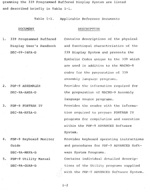
The available documents which contain information useful in pro-gramming the 339 Programmed Buffered Display System are listed and described briefly in Table 1-1.
Table 1-1.
DOCUMENT
1. 339 Programmed Buffered Display User's Handbook DEC-09-l6FA-D
2. PDP-9 ASSEMBLER DEC-9A-AMZA-D
3. PDP-9 FORTRAN IV DEC-9A-KFZA-D
4. PDP-9 Keyboard Monitor Guide
DEC-9A-MKFA-D
5. PDP-9 Utility Manual DEC-9A-GUAB-D
Applicable Reference Documents
DESCRIPTION
contains descriptions of the physical
and functiopal characteristics of the 339 Display System and presents the Symbolic Codes unique to the 339 which are used in addition to the MACRO-9
codes for the preparation of 339 assembly language prOgrams.
Provides the information required for the preparation of MACRO-9 Assembly language source programs.
Provides the reader with the
informa-tion required to prepare FORTRAN IV programs for compilation and execution wi thin the PDP-9 ADVANCED Sofbvare System.
Provides keyboard operating instructions and procedures for PDP-9 ADVANCED Soft-ware System Programs.
Contains individual detailed de scrip-tions of the Utility programs supplied with the PDP-9 ADVANCED Software System.
[image:6.615.68.546.116.736.2]1.2 REQUIRED 339 SYSTEM PROGRAMS
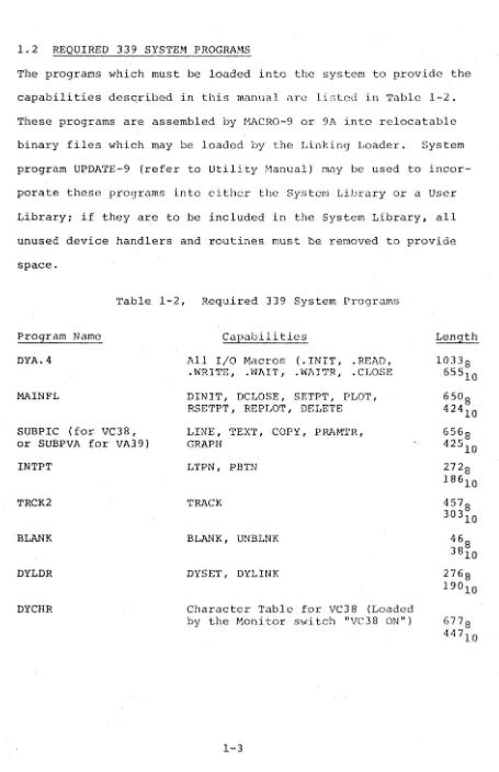
The programs which must be loaded into the system to provide the capabilities desqribed in this manual arc listed in Table 1-2. These programs are assembled by HACRO-9 or 9A into relocatable binary files which may be loaded by the Linking Loader. System program UPDATE-9 (refer to Utility Manual) may be used to incor-porate these programs into either the System Library or a User Library; if they are to be included in the System Library, all unused device handlers and routines must be removed to provide space.
Table 1-2, Required 339 System Programs
Program Name DYA.4
MAINFL
SUBPIC (for VC38, or SUBPVA for VA39) INTPT
TRCK2
BLANK
DYLDR
DYCHR
Capabilities
All I/O Macros (.INIT, .READ, .WRITE, .WAIT, .WAITR, .CLOSE DINIT, DCLOSE, SETPT, PLOT, RSETPT, REPLOT, DELETE LINE, TEXT, COPY, PRAMTR, GRAPH
LTPN, PBTN
TRACK
BLANK, UNBLNK
DYSET, DYLINK
Character Table for VC38 (Loaded by the Monitor switch "VC38 ON")
Length 10338
65510
65°8 42410 656 8 425
10 272 8 18610 4578 303
10 46
[image:7.615.75.530.32.736.2]1.3 SYSTEM DESCRIPTION
The Type 339 Progranuned Buffered Display (Frontispiece) is an on-line system manufactured by Digital Equipment Corporation for operator observation, manipulation, and alteration of compute r-stored data. The display system consists of a precision incre -mental CRT display, display control logic, light pen, pushbutton control box, and interface logic for communication with a PDP-9 computer. The computer processor and the display control logic share the computer memory, and are interdependent as a system.
The computer system furnishes rapid data storage and retrieval of data for display as dots, lines, curves, or characters (optional) on the face of the CRT. The operator can manipulate or alter the data by using the light pen, prishbutton control box, or the keys and switches on the computer console.
The Type 339 Progranuned Buffered Display interfaces to the PDP-9 general purpose computer through the optional Direct Memory Access Channel Multiplexer Adapter, Type DM09A. The result is a multi-processor system in which both the display multi-processor and the com-puter's central processor operate out of the same core memory on a time-shared basis.
The direct memory access channel (DMA) interface permits the 339 Display to operate from the PDP-9 memory, obtaining its instruc-tions on a cycle-stealing basis while allowing the PDP-9 to process a completely separate program. The PDP-9 can quickly interrupt this program, to service real-time interrupts generated by the operator, the display, or other external devices. The use of a conunon memory
for the display and the PDP-9 allows the computer to update the display files quickly, with a minimum of communication problems.
The 339 display system executes instructions contained in lists (groups of consecutive locations) in the shared memory. These lists are compiled from FORTRAN or symbolic language (MACRO-9) source programs or are loaded into memory from an external source.
Once a display program is loaded and compiled, the PDP-9 supplies the starting address of the list to the 3~9 display system and commands the display to begin. At this point, the PDP-9 is free to execute a completely separate program, pausing only to service interrupts caused by the display light pen, pushbutton control box, or other external source.
Display programs may consist of continuous loops of instruction or of chains comprised of several widely scattered lists. In either case the display is kept running continuously by the use of jump or jump-to-subroutine instructions which can be used to (1) direct the display processor, (2) proceed to the next list, or (3) return to the beginning of the current list. Skip instructions, used by the type 339 display, cause the display processor to test for specified conditions and to branch to different programs if the condi tions are met.
1.3.1 Easy Man/Machine Interaction
with the display system. The light pen allows the operator to "point" to a particular portion of the display and indicate that a change is desired. With tracking subroutines, the light pen can be used to "draw" lines and figures.
The pushbutton control box also provides a simple means of com-munication with the system. It features 12 pushbuttons, in two banks of 6 buttons each, a manual reset button for each bank, and a manual interrupt button that can be used to cause a PDP-9 program interrupt.
The activation of any pushbutton is sensed by the computer which then enters an interrupt mode. In the interrupt mode the processor will perform any operation specified as the response to the activated pushbutton.
1.4 339 SOFTWARE OPERATIONS
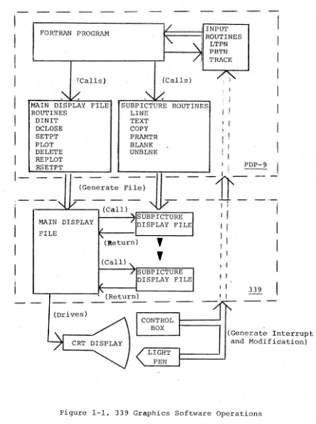
A functional block diagram illustrating the overall software
operations performed in the 339 system is shown in Figure 1-1. The FORTRAN IV programs devised by the user will consist of standard FORTRAN IV statements and calls for routines unique to the 339 Graphics system:
1) MAIN DISPLAY FILE ROUTINES - Calls for these routines together with the standard FORTRAN IV statements will, when com-piled, build a "Main Display File" in a portion of the PIW-9 memory assigned to the 339 Display system. The commands contained by tllis file will, during execution of the program, link together individual Subpicture Display Files into a CRT display command chain which will .cause the desired image to be displayed.
I
I
I
I
I
I
I
I
1-FORTRAN PROGRAM
'Calls)
MAIN DISPLAY FILE ROUTINES DINIT DCLOSE SETPT PLOT DELETE REPLOT RSETPT
. INPUT
~=====:jll
ROUTINES(Calls)
I
LTPN PBTN TRACKSUBPICTURE ROUTINES LINE
TEXT
COpy I I
PRAMTR BLANK UNBLNK
. I PDP-9
~Generate
File)-II - --11 _
.
~
I 'I--~~--" (Call)
I
~----~ISUBPICTURE MAIN DISPLAY
FILE
(Drives)
DISPLAY FILE (Return)
,
,
(Call)SUBPICTURE DISPLAY FILE , (Return)
I
,
'
,
I ,
339
I
I
I
CONTROL BOX(Generate Interrupt and Modification)
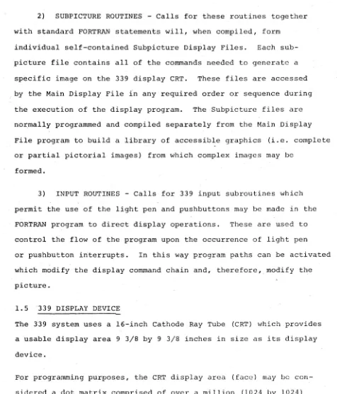
[image:11.617.83.527.75.670.2]2) SUBPICTURE ROUTINES - Calls for these routines together with standard FORTRAN statements will, when compiled, form
individual self-contained Subpicture Display Files. Each sub-picture file contains all of the commands needed to generate a specific image on the 339 display CRT. These files are accessed by the Main Display File in any required order or sequence during the execution of the display program. The Subpicture files are normally programmed and compiled separately from the Main Display File program to build a library of accessible graphics (i.e. complete or partial pictorial images) from which complex images may be
formed.
3) INPUT ROUTINES - Calls for 339 input subroutines which permit the use of the light pen and pushbuttons may be made in the FORTRAN program to direct display operations. These are used to control the flow of the program upon the occurrence of light pen or pushbutton interrupts. In this way program paths can be activated which modify the display command chain and, therefore, modify the picture.
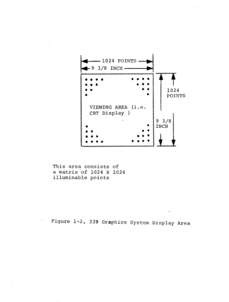
1.5 339 DISPLAY DEVICE
The 339 system uses a 16-inch Cathode Ray Tube (CRT) which provides a tisable display area 9 3/8 by 9 3/8 inches in size as its display device.
For programming purposes, the CRT display area (face) may be con-sidered a dot matrix comprised of over a million (l02~ by l02~)
illuminable points (dots) spaced a~ about 0.01 inch intervals (see Figure 1-2). For display purposes, the matrix dots are illuminated,
[image:12.614.65.541.58.615.2]~
1024 POINTS-J 9 3/8 INCH---e..t• •••
•
•
•
•
•
•
•
•
•
•
•
••
•
•
•
VIEWING AREA (i.e. CRT Display )
---...
....
1024 POINTS
9 3/8
•
• INCH•
•
• •
•
•
• •
•
This area consists of a matrix of 1024 X 1024 illuminable points
•
•
• •
•
••••
[image:13.613.73.541.86.701.2]selectively, by an electron beam generated within the CRT. The illumination of a series of dots in any direction results in a visually continuous line of uniform resolution. Images are
developed on the 339 CRT display by the controlled generation and positioning of the CRT electron beam in direct response to a
programmed instruction list processed by the 339 system.
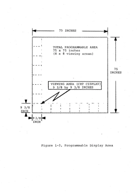
1.5.1 Programmable Display Area (Refer to Figure 1-3)
Although the CRT display area is physically limited to a 9 3/8 by 9 3/8 inch area, the hardware capabilities of the 339 system permit the user to develop images up to 8 times the display area in size. For programming purposes, the available (programmable) drawing area may be considered as a 75 by 75 inch sheet of paper on which one or mor~ images may be developed.
Viewing any part of the programmable drawing area is accomplished by program features which, in effect, cause the "drawing sheet" to move under the viewing window (i.e. CRT display) to any desired position.
1.5.2 Program-controlled CRT Characteristics
Display Scale and Intensity are variable display characteristics which must be specified by the programmer in each display program. Two control functions, Light Pen on/off and Blink on/off are also programma ble .
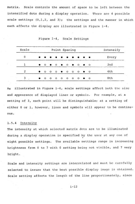
1.5.3 Scale
As previously described, images are generated on the display CRT by the controlled intensification of points within the display dot
9 3/8 INCH
_ _ _ I
-
-
-~---.,
1~9 3/8~
INCH75 INCHES
TOTAL PROGRAMMABLE AREA 75 x75 inches
(8
x
8 viewing areas)VIEWING AREA (CRT CISPLAY) 9 3/8 by 9 3/8 INCHES
75 INCHES
[image:15.612.76.532.54.702.2]matrix. Scale controls the amount of space to be left between the
intensified dots during a display operation. There are 4 possible
scale settings (0,1,2, and 3); the settings and the manner in which
each affects the display are illustrated in Figure 1-4.
Figure 1-4, Scale Settings
Scale Point Spacing Intensify
0
• •
•
•
•
•
•
•
•
•
Every1
•
0•
0•
0•
0•
0 2nd2
•
0 0 0•
0 0 0•
0 4th3
•
0 0 0 0 0 0 0•
0 8thAs illustrated in Figure 1-4, scale settings affect both the size
and appearance of displayed lines or symbols. For example, at a
setting of 3, each point will be distinguishable; at a setting of
either 0 or 1, however, lines and symbols will appear to be
continu-ous.
1.5.4 Intensity
The intensity at which selected matrix dots are to be illuminated
during a display operation is specified by the user at any one of
eight possible settings. The available settings range in increasing
brightness from 0 to 7 with 0 setting being not visible, and 7 very
bright.
Scale and intensity settings are interrelated and must be carefully
selected to insure that the best possible display image is obtained.
Scale setting affects the length of the line proportionately, since
[image:16.615.67.539.61.772.2]the increments given are actually a count of intensified points rather than absolute points. Therefore, i t affects the intensity in inverse proportion since fewer points are glowing. Thus if the intensity of a line must remain constant with a change in scale set-ting, the intensity setting must be changed by an equal amount. At a scale setting of 2, the points are clearly separated and the
.effect on intensity becomes secondary.
1.5.5 Blink Control Function
The ability to cause a displayed image or portion of the image to blink on and o£f at a visually discernible rate is a function which may be specified by the programmer.
The display "Blink" feature may be specified for any display file whether i t represents an entire display or specific portion of a display. This feature is particularly useful when i t is necessary to draw attention to specific displayed items.
The blink on/off control element is represented by an integer variable the value of which could, if desired, be made a function of the state of one of the control pushbuttons on the 339 control box.
1.5.6 Light Pen Control Function
the increments given are actually a count of intensified points rather than absolute points. Therefore, i t affects the intensity in inverse proportion since fewer points are glowing. Thus if the intensity of a line must remain constant with a change in scale set-ting, the intensity setting must be changed by an equal amount. At a scale setting of 2, the points are clearly separated and the
.effect on intensity becomes secondary.
1.5.5 Blink Control Function
The ability to cause a displayed image or portion of the image to blink on and o£f at a visually discernible rate is a function which may be specified by the programmer.
The display "Blink". feature may be specified for any display file whether i t represents an entire display or specific portion of a display. This feature is particularly useful when i t is necessary to draw attention to specific displayed items.
The blink on/off control element is represented by an integer variable the value of which could, if desired, be made a function of the state of one of the control pushbuttons on the 339 control box.
1.5.6 Light Pen Control Function
The ability to use the light pen supplied with the 339 system is also a programmed function; the user must specify if the light pen is to be enabled or disabled throughout the display operation or is to be controlled from the 339 control box.
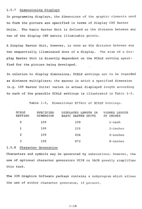
1.5.7 Dimensioning Displays
In programming displays, the dimensions of the graphic clements used to form the picture are specified in terms of Display CRT Raster Units. The basic Raster Unit is defined as the distance between any two of the display CRT matrix illuminable points.
A Display Raster Unit, however, is seen as the distance between any two sequentially illuminated dots of a display. The size of a Dis-play Raster Unit is directly dependent on the SCALE setting speci-fied for the picture being developed.
In relation to display dimensions, SCALE settings are to be regarded as distance multipliers; the manner in which a specified dimension
(e.g. 109 Raster Units) varies in actual displayed length according to each of the possible SCALE settings is illustrated in Table 1-3.
Table 1-3, Dimensional Effect of SCALE Settings.
SCALE SPECIFIED DISPLAYED LENGTH IN VIEWED LENGTH SETTING DIMENSION BASIC RASTER UNITS IN INCHES
a
109 109 I-inch1 109 219 2-inches
2 109 436 4-inches
3 109 872 8-inches
1.5.8 Character Generation
Characters and symbols may be generated by subroutines; however, the use of optional character generators VC38 or VA38 greatly simplifies this task.
[image:19.617.61.545.37.747.2]CHAPTER 2
GRAPHIC SUBPROGRAM ROUTINES
This section contains detailed descriptions of the FORTRAN IV CALL statements required for each 339 Graphic Subprogram. Each descrip-tion also includes the equivalent statem~nts needed to call the subprogram in MACRO-9.
All display file storage is supplied by the user in the form of dimensioned integer arrays. To facilitate s£orage management, the first location of each display file contains the length of the file. Limited reuse of storage is provided for in Main Display File rou-tines REPLOT and DELETE. The storage requirements of each CALL which adds commands to a file are indicated in the description given of the CALL.
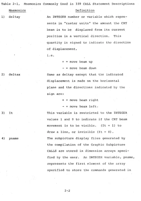
Table 2-1, Mnemonics Commonly Used in 339 CALL Statement Descriptions Mnemonics
1) deltay
2) deltax
3) It
4) pname
Definition
An INTEGER number or variable which repre-sents in "raster units" the amount the CRT beam is to be displaced from its current position in a vertical direction. This quantity is signed to indicate the directi6n of displacement.
1. e.
+
=
move beam upmove beam down
Same as deltay except that the indicated displacement is made on the horizontal plane and the directions indicated by the sign are:
+
=
move beam right move beam left.This variable is restricted to the INTEGER values 1 and 0 to indicate if the CRT beam movement is to be visible. (It 1) to draw a line, or invisible (It
=
0) . [image:21.612.70.548.64.745.2]~'0T~:
T-·.:....·:: ~~~ . .=.= ':':"':~:~':
fro~ the state~e~t
argument list~; if dropped, the last given value for pname will be assumed.
5) featr
6) value
7) mainfl
8} cname
~ .... :.' .
-is located. F:a::1e is ah:3~'3 repr8sl~l1tcd as
a subscripted variable; i t will contain the length of the file and is the variable by which the file is referenced in later
manipu-lations.
An INTEGER number which identifies a feature of the CRT display to be specified in the CALL
(i.e. 1
= SCALE,
2=
Intensity, 3=
light pen, and 4= Blink) .
A single INTEGER digit which. indicates what value or setting is specified for the selected display feature.
Similar to pname, the value of mainfl repre-sents the first array element of the dimen-sioned array specified by the user to store a Main Display File. Mainfl is represented as a subscripted INTEGER variable, i t contains the length of the file and is the variable by which the file is referenced.
An INTEGER which identifies the location or
first location which contains the display command(s) generated by the CALL in which cname is an argument.
2.1 SUBPICTURE ROUTINES
The 339 subpicture routines generate files of executable display commands which are identified and manipulated as separate graphi-cal entities (i.e. Subpicture Display Files). The identity of a subpicture file is the address of its first location (pname) and is given as an argument in all calls to the subpicture routines. The calls are self-contained; they permit simultaneous generation of subpictures with each referenced subpicture left in displayable form so that i t can be manipulated dynamically while displaying.
The first location of a subpicture (pname) contains its current
length; this value must be ~ when the first reference to the Sub-picture Display file is made. After the first reference, the
value of pname is maintained by the subpicture routine.
Since display files are generated and stored in arrays dimensioned by the user, they are fully accessible to the user and can be written out or read in using FORTRAN unformatted I/O statements.
Storage overhead for each Subpicture Display File is three words: 'the first word contains the file length, the second is used for
con-trol and the third (last in file) contains the 339 display command
2.1.1 LINE Subroutine
The LINE subroutine adds to the specified subpicture file the com-mands necessary to draw a line (beam intensified) or move the beam
(not intensified) through a specified displacement from the current beam position.
a.
b.
Form
(1) FORTRAN: CALL LINE (del tay, deltax, It
Gpnam~)
(2 ) Macro-9:
.GLOBL LINE
JMS* LINE
JMP .+5
.DSA deltay .DSA deltax
.DSA It
[DSA
pnam~
Input Variables
(1) deltay = Vertical component of beam displacement in raster units (integer).
(2) deltax
=
Horizontal component of beam displacement in raster units (integer).(3) It
=
Line type (integer). 1 visibleo
invisible(4) pname is the first location of this subpicture display file. It is the name by which the subpicture is referred to in later manipulation. For example, if a subpicture is to start in the dimensioned array ELEMNT, the calls to LINE building that subpicture are of the form CALL LINE (deltay, deltax, It, ELEMNT(l» (integer). c. Output Variables
d. Description
(1) LINE adds three commands to the display file: VEC!EDS
.11'1 t :)y
,j •• ) t ,J Z
(vector mode, enter dRta state)
( •. : ; ( : .1) }. '.' t. () .. c ( ) /I L t ( ) I. -:; L, I
'
,
r .
)
)
j L (lIl)(2) If it immediately follow~ another LINE call, LINE clears the preceding escape bit and adds 2 commands to the display file:
deltay
deltax (escape bit on)
(3) The number of commands added to the display file is added to the contents of 10Gation pname.
e. Restrictions
(1) Deltay and deltax are signed integprs, the magnitudes of which must not exceed 1023.
(2) Pname must contain zero before the first call referenc-ing it.
(3) Sufficient space must follow pname to contain the subpicture file.
f. Example. The following two statements illustrate the use of the LINE subroutine to draw straight and sloped lines:
(1) Draw a vertical line: Display .
CALL LINE(50,0,1~ILINE
(I»
l}
.
Vert. line 50 Raster units
. long
~ Starting point
(2) Draw a sloped line:
CALL LINE(200,-300,1,ILINE(1» x == -300
~
~}y
== 2002.1.2 TEXT Subroutine
This subroutine call may be used only ~n 339 systems which contain an optional character generator (VC38 or VA38) .
The TEXT subroutine adds to the specified subpicture file the com-mands necessary to display the identified text string, starting at the current beam position. These are in the format determined by whichever of the optional character generators (VC 38 or VA38) is used.
The standard text font is drawn on a 5 x 7 dot matrix. Each character causes an incr.ement of 7 raster units to the X position of the beam.
a. Form
(1) FORTRAN: CALL TEXT · (s tr, n ~pnam~ )
(2) Macro-9
b. Input Variables
.GLOBL JMS* JMP
.DSA .DSA EDSA
TEXT TEXT .+4 str n
pnam~
(1) str identifies the dimensioned real array which contains the string of characters to be dis-played in lOPS ASCII (Hollerith) form (five 7-bit characters per word).
(2) n is an integer number representing the total number of characters to be displayed.
(3) pname is the first location of this subpicture file, as in LINE, above.
c. Output Variables
pname
=
Curtent length of this file. d. Description(1) TEXT adds to the assembled display file two commands
plus the character string at two characters per word:
CIIAR!EDS (character mode, enter dat a state)
Cl C2
Cn
Ce (escape-to-control-state character)
(2) If this TEXT call immediately follows a previous TEXT
call, TEXT inserts only the new character string
above the escape character.
(3) The number of commands added to the file is added to
the contents of pname.
e. Restrictions.
(1) Pname must contain zero (S) before the first call
referencing it.
(2) Sufficient space must follow pname to contain the
subpicture file.
f. Example
The following statements illustrate the manner in which
text to be displayed is setup and called:
(1) Setup for "339JSSABET~LLEYI
DIMENSION ADDR(4)
DATA ADDR(1)/5H339uA/,ADDR(2)/5HSSABE/,ADDR(3)/5HT~LL/,
. 1 ADDR (4) /2HEY/
(2) CALL statement to display text
2.1.3 COpy Subroutine
The COpy subroutine enables two or more subpicture display files to
be linked together to generate a composite display image. This
sub-routine adds to one subpicture display file the commands necessary to
link i t to a second subpicture with the second display file starting
at the last beam position specified by the first subpicture.
a. Form
(1) FORTRAN: CALL COpy (pname1 GpnameJ)
(2) Macro-9:
b. Input Variables
.GLOBL JMS* JMP .DSA EDSA
COpy COpy .+3 pnamel
pnam~
(1) pnamel is the first location (name) of the suupicture
to be copied (integer).
(2) pname is the first location (name) of this subpicture
display file, as in LINE above.
c. Output Variables
pname
=
Current length of this file.d. Description
(1) COpy adds two commands to the display file:
PJMP (display subpicture jump)
pnamel+2
(2) 2 is added to the contents of pnamel.
e. Restrictions
(1) Pnamel need not be defined when COpy is called, but
must be a defined subpicture when pname is displayed.
(2) Pname must contain zero
un
before the fir~,t ca] 1referencing it.
(3) Sufficient space must follow pname to contain the
subpicture file.
f. Example
The statement
CALL COpy (WINDOW (1) ,HOUSE(l))
adds a call to the WINDOW subpicture file to the file identified as HOUS&.
2.1.4 PRAMTR Subroutine
The PRAMTR subroutine allows the user to add to the specified
sub-picture file the commands necessary to set scale and intensity for the display or to turn on or off light pen sen~itivity and the blink circui t.
The scale setting determines the proximity of intensified points in a line:
o
Every poin t is intcn;.i fir·d1 Every other point is intensified 2 Every fourth point is intensified 3 Every eighth point is intensified This setting affects the length of the line proportionately, since the increments given in the LINE call are actually a count of
intensified points rather than absolute points. It also aff~cts the intensity, in inverse proportion, since fewer points are glowing.
Thus if the intensity of a line must remain constant with a change in scale setting, the intensity setting must be changed by an equal amount. At a scale setting of 2, the points are clearly separated and the effect on intensity becomes secondary.
More than one feature, each with its corresponding settings, may be specified in a PRAMTR CALL statement by using the following technique:
selected features and assign this value to the variable featr.
Example: for scale (1) and intensity (2) featr will have the value 3.
(2) List the desired settings~ as arguments, in ascending order according to the values of the numeric assigned to their corresponding features (the argument list 3,2,6 would specify a value of 2 for scale (#1) and of 6 for
intens~ty (#2».
a. Form
(1) FORTRAN:
A. (one feature) CALL PRAMTR (featr, value [pnam~ ) B. (more than one feature and setting)
CALL PRAMTR (featr(s) ,valUeltValuc2 . . .
J
Epnamc])(2) Macro-9:
.GLOBL JMS* JMP
.DSA .DSA .DSA
MODE MODE .+N featr value pname
Where: N
=
2+ (number of features specified) +1 if pname is givenb. Input Variables
(1) featr
=
Feature of the display being set (integer): 1 set scale2 set intensity
4 set light pen sensitivity (on or off) 8 set blink (on or off)
(2) value == The value to which featr is set (integer) Featr Possible Values
1 (scale) 0 (low)
-
3 (high)2 (intensity) 0 (low) - 7 (high)
;} llight pen} 1 - on 0 off
8 (blink) 1 on
0 off
(3) Pname is the first location of this subpicture file,
as in LINE, above. c. Output Variables
pname
=
Current length of this file. d. Description(1) The PRAMTR subroutine adds one or mor€ commands to the display file depending on the type of argument list used:
SC value or INT value or LPON if value BKON if value
1, LPOF if value 1,. BKOF if value =
(2) 1 is added to the contents of location pname. e. Restrictions
0, or
o
(1) This subroutine must be used with care, since the setting given is in effect until explicitly changed in this or some other part of the display. Thus, if the blink is turned on at the beginning of a sub-picture, i t must be turned off at the end in order that only that subpicture blinks. Otherwise the whole display will blink.
(2) Pname must contain zero (~) before the first call referencing it.
(3) Sufficient space must follow pname to contain the subpicture file.
f. Examples:
(1) The following single feature statement: CALL PRAMTR (2,7,HOUSE(1»
specifies an intensity (2) level of 7 for the subpicture display file starting at the first location of array HOUSE.
(2) The following multiple-feature statement: CALL PRAMTR (SCALE+INT+LPEN,~,4,1,IN(1»
dis-2.1.5 GRAPH Subroutine
The GRAPH subroutine adds to the specified subpicture file the
com-mands necessary to display in graph form the identified set of data
points. One coordinate is sequentially set at the value of each
data point. The other coordinate is then automatically incremented
by one (in the current scale), leaving the beam positioned one
increment past the end of the graph. Note that axis and labelling
must be provided separately.
a. Form:
(1) FORTRAN: CALL GRAPH
(2) .Macro-9:
b. Input Variables
.GLOBL JMS* JMP
.DSA .DSA .DSA [DSA
GRAPH GRAPH
.+5 dta
n
a pnameJ
(1) dta contains the set of data points, one per word, in
the range 0 to 1023 (integer).
(2) n
=
number of data points to be displayed (integer).(3) a indicates which axis to imcrement.
~
=
increment x, set y to data values1
=
increment y, set x to data values(4) pname is the first location of this subpicture file,
as in LINE, above.
c. output variables
pname
=
current length of this file.d. Description
(1) GRAPH adds to the display file one cOlrunand plus the
data set, at one value per word:
GRAPH!EDS (graph mode, enter data state) VALl
VAL2
VALn (escape bit on)
(2) If this GRAPH call immediately follows a previous GRAPH call, the escape bit is cleared and the new data points only are added to the file. The escape bit is then set in the last of the new data points. (3) The number of commands added to the file is added to
the contents of pname. e. Restrictions
General restrictions only (see LINE) . f. Example
The following program illustrates the use of the GRAPH and other subroutines.
CTEST pr~r)GRfl"1 FflK THt: GRAPH SU8ROUT I ,\I[
e
FTSTlv)COP Y R I,; H T 1969. [I I r, I TAL F (,I U I PM F N TeO R P •• .>1 A Y N A '~D. MAS S • I ." T E G [ (J S I ;" \'j V ( 3110) • Y ( 2'" 0 )
nI~[NSIU~ TITL(1~),MAINFL(2~)
OATA TITL(1),TITL(2),TITL(3),TITL(4)/5HTHIS , 1 ,~HIS A ,~HSINE ,5H~AVE.I
C SET d
r
I N TF G F R A i~ RAY 0 F V A L LJ EST 0 BE P L LJ TT F [) 1 ~x
=
~',•
11020 1=1,?00
y( I )=IFI X(SIN(X)"256. )+512 X=X+.;(1I'-,)>'
20 CO~.IT 1 i\jlil
C SET .lP SUB-PICTURE TO PLOT THOSE VALUES
SIN W V ( J)
=
(1C~LL P~AMTR(3,~,7,SINWV(I» CALL L1NF(~,45~,I)
CALL LINF(?50,-450,0) CALL LI NF(-?00,~,1) CAL L L I ~~ (:" ( ? 5 0 , "" , 0 ) CALL PHAr-1TR(1.1>
CALL G~APH( '((1> ,100,0)
CALL GPAPH(Y(101),100,~,SINWV(])1 CALL Ll ~(:"(-2~,-2~0,~)
C SET '~"1 II I r"; I; I ~, ~'I. A Y F I LET 0 n [ S P lAY T H r:- r, R A ~ H
,'.\ A l-.J r L ( 1 )
= :/'
CAL L ,.\ i ,'J [ T ( "'; A I NFL ( 1 ) )
CALL 'JiTI'-'T(?12.2Vi0)
C A. L L P L f) T ( ',; • SIN W V ( 1 ) )
PALJSF 1
rALL ""L,'sr (MAINFl(U)
I')A'h~ "
(;1) fl\ : 0,
r (~"
2.1.6 BLANK Subroutine
The BLANK subroutine is used to prevent the displaying of any copy of this subpicture. The display file length is not changed.
a. Form
(1) FORTRAN: CALL BLANK (pname) (2) Macro-9:
b. Input Variables
.GLOBL JMS* JMP
.DSA
BLANK BLANK
.+2 pname
pname is the subpicture to be BLANKed. c. Output Variables
None.
d. Description
(1) The command in location pname+2 (the first executable command in the display file) is moved to location pname+l.
(2) The command POP (display subpicture return) is inserted at location pname+2.
e. Restrictions
(1) Pname must be a defined sUbpicture file.
(2) BLANK has no meaning as the first call referring to pname.
f. Example
Th~ following statement prevents the subpicture diSplay file starting at the first location of array IPIC from being displayed.
CALL BLANK (IPIC(l))
2.1.7 UNBLNK Subroutine
The UNBLNK subroutine reverses the action of the BLANK subroutine, allowing a previously BLANKed subpicture to be displayed.
a. Form
(1) FORTRAN: CALL UNBLNK (pname) (2) Macro-9:
b. Input Variables
.GLOBL JMS* JMP
.DSA -;,'
UNBLNK UNBLNK
.+2 pname
pname is the subpicture to be UNBLNKed. c. Output Variables
None.
d. Description
The command in locationpname+l (placed there by a call to BLANK) is moved to location pname+2, overlaying the POP that was there.
e. Restrictions
(1) Pname must be a defined subpicture file.
f. Example
The following statement will enable the previously blanked subpicture IPIC (refer to "f." of 2.1.6) to be displayed.
CALL UNBLNK (IPIC(l))
2.2 MAIN DISPLAY FILE ROUTINES
These routines are used to generate the display main file, to which the display controller is directed when initiating display, and which is presumed to be calling upon the subpicture files generated with the routines described above. As is the case with subpicture
files, storage used for the main file is supplied by the calling program as a dimensioned array. That array is identified by only
one call to the initializer (DINIT) and is implicit in all other calls. These calls assume that reference is m~de to tIle storage identified by DINIT. They are concerned, however, with the identification of each entry to the main display file. Thus each call has as an
optional argument the location of the display code generated by that particular call which provides a "handle" to that par~icular graphic entity. This provides the flexibility required to build and modify a display file in an interactive environment. It also enables the user to perform limited storage management. Each routine that adds commands to the file inserts a word count corresponding to this call, and each change or deletion of commands updates this local word count. Thus, small blocks of storage containing unneeded commands can be reused.
As with subpicture files, the name of a main display file is its first
loc~tion, which contains the length of the file and is updated by
each call that changes that length. If a new file is to be generated, the first location must contain zero before any display routines refer
to it. The remaining three words of storage overhead in a main file are the second word, reserved for control, and the last two words,
\vhich contain a· JUMP to the beginning of the file. The local word counts keeping track of groups of commands are kept in the high-order
6 bits of the PDP-9 word, since the display uses only the low-order 12 bits.
2.2.1 DINIT (Display Initialize) Subroutine
The DINIT subroutine initializes the display via device number
(.DAT slot) 10. The 339 Device Handler must be associated with .bAT slot 10 as DINIT contains .IODEV 10, which causes the deVice handler tied to .DAT slot 10 to be loaded. It can be used to set up for a new display main file, to start up an old one, or to start up any previously defined subpicture as the current main file.
a. Form
(1) FORTRAN: CALL DINIT (mainU)
(2) Macro-9:
b. Input Variables
.GLOBL JMS* JMP
.DSA
DINIT DINIT .+2 mainfl
mainfl is the first location of the main display file. Like pname, i t is an element of a dimensioned array (integer). c. Output Variables
Location mainfl contains the length of the display file. This is updated by all Main File Routines.
d. Description
(2) Insert JUMP mainfl+2 at end of file.
(3) Initialize display.
(4) Start the display running at mainfl+2.
e. Restrictions
(1) If a new display file is being formed, location mainfl must contain zero. If this is a previously defined
file, mainfl contains the file length and must not be altered.
(2) Sufficient storage must follow mainfl to accommodate the display file to be generated at anyone time. (3) Only one main display file can be running at anyone
time. f. Example
The following statement initializes the execution of the Main Display File starting at the first location of array MAINFL.
CALL DINIT (MAINFL (1»
2.2.2 DCLOSE (Display Terminate) Subroutine
The DCLOSE subroutine is used to end a display. It also converts the main file specified into a subpicture file by replacing the JUMP to the starting location by a POP command. This allows i t to be used by any subsequently generated main file, as subpicture mainfl.
a. Form
(1) FORTRAN: CALL DCLOSE (mainfl)
(2) Macro-9:
b. Input Variables
.GLOBL JMS* JMP
.DSA
DCLOSE DCLOSE
.+2 mainfl
mainfl is the starting location of the main display file
being closed.
c. Output Variables
Nonc.
d. Dc~;ct":i.pLi()J)
(I) ~:t"l' nllllli.ll<1 till' di',pL,y device.
(2) Insert POP at the last location of the display file.
e. Restrictions
None.
f. Example
The following statement will end the display initiated by
the statement given in the example "f." of 2.2.1.
CALL DCLOSE (HAINFL (1»
2.2.3 SETPT (Set Point) Subroutine
The SETPT subroutine is used to locate the beam on the display sur-'
face in absolute display coordinates (raster units). The beam is
not intensified with this call.
a. Form
(1) FORTRAN: CALL SETPT (y, x
G
cnameJ )(2) Macro-9:
.GLOBL SETPT
JMS* SETPT
JMP .+4
.DSA Y
.DSA x
b. Input Variables
(1) y vertical coordinate of beam location. (2) x
=
Horizontal coordinate of beam location. c. Output Variables(1) cname
=
Location of the group of display commands generated by this call (Integer Variable) .d. Description
(1) SETPT adds three commands to the main file: POINT!EDS
Y
x
(point mode, enter data state)
(2) The number 03 is entered into the high-order six bits of the control state command (POINT!EDS).
(3) The value 3 is added to the content s of location mainfl.
(4) The location of the POINT!EDS is stored 1n cname (if given).
e. Restrictions
(1) The values x and y must be positive integers, and their values must not exceed 1023.
(2) This call causes the beam to be given an ~bsolute location, as opposed to a relative displacement. This action effectively severs any following parts of the display from any preceding parts. If a section of the display is completely defined in terms of relative vectors, then its location on the display surface depends on where the beam was initially located~ and i t can be made to move as a unit by changing the
initial setting. Giving the beam an absolute location disregards any previous motion and serves as a new reference point in the display.
(3) Cname is an optional output of this subroutine. Using the same variable name as one used in a previous call will destroy the previous contents.
f. Example
The following statement establishes an absolute beam position at matrix coordinates y=lO, x=lO of the display.
CALL SETPT (l~,l~)
2.2.4 PLOT Subroutine
The PLOT subroutine is the prime active agent in the generation
of the main di~play file. There are three forms of calls correspond-ing to the three subpicture routines, COPY, LINE, and PRAMTR. They are used to cause the displaying of predefined (but not necessarily complete) subpictures and individual lines, and to introduce appro-priate display control commands. In all cases, the requested
display or control function is identified as a separate entity and may be manipulated independently of the rest of the display. A. PLOT a Subpicture
a. Form
(1) FORTRAN: CALL PLOT (~,pname [cnameJ) (2) Macro-9:
b. Input Variables
.GLOBL JMS* JMP
.DSA .DSA EDSA
PLOT PLOT .+4
(~
pname
cnam~
pname is the name (first location) of the subpicture to be displayed.
c. Output Variables
cname = Location of the group of display commands generated by this call .
. d. Description
(2) The number 02 is entered into the high-order six bits of the PJMP.
(3) The value 02 is added to the contents of mainfl.
(4) The location of the PJMP is stored in cname (if given). e. Restriction
As in SETPT, cname is an output and multiple use of the same variable name will destroy previous contents.
f. Example
CALL PLOT (COPI,HOUSE(l) ,MAIN) where: COPI has been assigned the integer- value
g
by a DATA statement; HOUSE identifies the 5ubpicture file to be displayed and MAIN is an optional variable by which this display may be referenced.B. PLOT a Line (or reposition the beam) a. Form
(1) FORTRAN: CALL PLOT (1 ,del tay, del tax, It [cnameJ ) (2) Macro-9:
b. Input Variables
.GLOBL JMS* JMP
.DSA .DSA .DSA .DSA [DSA
PLOT PLOT .+6
(I deltay deltax It
cnam~
(1) deltay
=
Vertical displacement through which the beam is to move.(2) deltax
=
Horizontal displacement through which the beam is to move.(3) It
=
Line type. 1 visibleo
invisiblec. Output Variables
cname
=
Location of the group of display commands generated by this call.d. Description
(1) Three commands are added to the main display file: VEC!EDS
deltay deltax
(vector mode, enter data state) (intensify bit
=
LT)(escape bit on)
(2) The number 03 is entered into the high-order six bits of the VEC!EDS.
(3) The value 03 is added to the contents of mainfl.
(4) The location of the VEC~EDS is stored in cname (if given) . e. Restrictions
(1) Deltay and deltax are signed decimal integers not to exceed 1023.
(2) As in !JE'l'P'l', cname is an output and multiple use of the same variable name will destroy previous contents. f. Example
CALL PLOT (LYNE,l$l~~,l~~,ON,lEDGE(l))
where LYNE and ON have assigned values of 1 and lEDGE(l) is a display identifier to be used for later reference to this line.
C. PLOT a Control Command a. Form
(1) FORTRAN: CALL PLOT (2,featr,valueGcname])
(2) Macro-9:
.GLOBL JMS* JMP
.DSA .DSA .DSA
PLOT PLOT .+5 (2 featr value
b. Input Variables featr , value.
NOTE
The variables featr and value must be specified in the same manner as for PRAMTR statements. Refer to paragraph 2.1.4 for detailed information.
c. Output Variables
cname = Location of the group of dIsplay commands generated by this call.
d. Description
(1) This subroutine adds one or more commands .to the display file depending on the type of argument list used:
SC value or INT value or
LPON if value=l, LPOF if value=O or BKON if value=l, BKOF if value-O
(.2) The number 01 or more is entered into the high-order six bits of the command.
(3) The value 01 or more is added to the contents of mainfL (4) The location of the command is stored in cname (if given). e. Restrictions
(1) This call must be used with care, since the setting given is in effect until explicitly changed in this or some other part of the display. Thus if the blink is turned on before calling a subpicture, i t must be turned off after the call in order that only that subpicture blinks. Otherwise, the whole display will blink.
(2) As in SETPT, cname is an output and multiple use of the same variable name will destroy previous contents.
f. Example
(1) Single-feature statement CALL PLOT (2,8,1)
(2) Multiple-feature statement
CALL PLOT(PRAM,SCALE+INT+LPEN,fJ,4,l,IN)
establishes the values fJ and 4 for display feature SCALE and INT, turns the light pen option (LPEN) on,
and specifies the location IN as the first location of the array containing the display code generated by this statement (PRAM = 2).
2.2.5 DELETE Function
The function DELETE is used to delete from the main display file any display entity formed by a single call to a main fil~ subprogram and assigned to cname. If cname does not point to the beginning of such a display entity, the DELETE fails and has no effect on the display file.
a. Form
( 1) FORTRAN: i
=
DELETE (cname)or CALL DELETE (cname) (2) Macro-9:
b. Input Variables
.GLOBL JMS* JMP
.DSA DAC
DELETE DELETE
.+2 cname
i l i f desired
cname
=
Location of the group of display commands to be deleted.c. Output Variables
i
=
Boolean success indicator.d. Description
. TRUE. . FALSE.
successful deletion . unsuccessful deletion .
(2) Replace all commands in this group by display no-operation (NOP) commands.
(3) Insert sequential numbers in the high-order six bits of immediately adjacent free storage locations,
starting from the bottom of this group and moving up
in the display file. e. Restrictions
None· f. Example
CALL DELETE (NAME(2»
Deletes from the main display file the display entity whose first command is pOinted at or identified by the second element of array NAME.
2.2.6 REPLOT Function
The function REPLOT allows use to be made of previously defined locations in the milin display file. This can serve two purposes:
(1) to reuse locations freed by DELETE, and (2) to change an exist-ing group of display commands. REPLOT checks whether the group being inserted is longer than the space pointed at by cname . . If i t is, the REPLOT fails and the display file is not affected. By ma:nipulat-ing cname, smaller groups can be packed into the space formerly used by a larger group. For example, up to three control commands could be inserted into the space left by a DELETEd LINE group. There are three forms of calls to REPLOT, each of which is the same as the corresponding call to PLOT.
It is important to note that while cname is an optional output of PLOT i t is a required input of REPLOT since i t identifies the loca-tions to be modified in the main display file It also must be recognized that cname must have been given as an argument to a PLOT call for i t to be available for REPLOT.
A. REPLOT a subpicture a. Form
( 1) FORTRAN: i = REPLOT
(11,
pname., cname) or CALL REPLOT (copy,pname,cname) (2) Hacro-9:b. Input Variables
.GLOBL JMS* JMP
.DSA .DSA .DSA DAC
REPLOT REPLOT
.+4 (~ pname cname·
i l i f desired
(1) pname is the name (first location) of the subpicture to be displayed.
(2) cname
=
Location in which to store the display commands generated.c. Output Variables
i
=
Logical success indicator. . TRUE..FALSE.
REPLOT successful •
not enough room at location pointed to by cname, no action ..
NOTE: If the above form is used, both i and REPLOT must be declared as LOGICAL in a-type statement.
d. Description
(1) Check if cname points to a large enough block; do nothing if not.
(2) Insert two commands at the location pointed to by cname: PJMP
pname+2
(3) The number 02 is entered into the high-order six bits of the PJMP.
(5) Insert NOP's in any remaining locations belonging to a former command group at this address.
e. Restrictions None.
f. Example
CALL REPLOT ({if, SLIDE (H) ,NAME)
where ~ indicates the function (i.e. subpicture), M represents the first location of the subpicture display file (in array SLIDE) and NAME identifies the location in the display file into which this line is to be inserted. B. REPLOT a line (or reposition the beam)
a. Form
(1) FORTRAN: i
=
REPLOT (l,deltay,deltax,It,cname) or CALL REPLOT (line,deltay,deltax,It,cname) (2) Macro-9:b. Input Variables
.GLOBL JMS* JMP
.DSA .DSA .DSA .DSA .DSA DAC
REPLOT REPLOT
.+6
(l
deltay deltax It cname
i l i f desired
(1) deltay
=
Vertical displacement through which the beam is to move.(2) deltax
=
Horizontal displacement through which the beam is to move.(3) It = Line type. 1 visible
o
invisible(4) cname = Location in which to store the display commands generated.
c. Output Variables.
i Logical success indicator. . TRUE.
.FALSE.
REPLOT successful .
not enough room at location pointed at by cname, no action.
NOTE: If the above form is used, both i and REPLOT must be declared as LOGICAL in a type statement.
d. Description
(1) Check if cname points to a large enough block, do nothing if i t does not.
(2) Insert three commands at the location pointed to by cname:
VEC!EDS deltay deltax
(vector mode, enter data state) (intensify bit
=
It)(escape bit on)
(3) The number 03 is entered into the high-order six bits of the VEC!EDS.
(4) Subtract the value 3 from the sequential numbers in the high order six bits of any adjacent free storage locations above this.
(5) Insert NOPs in any remaining locations belonging to a former command group at this address.
e. Restrictions
Deltay and deltax are signed decimal integers not to exceed 1023.
f. Example
CALL REPLOT (LYNE,Y,X,OFF,DISPL)
where the first four arguments are assigned the values 1, 50, 50 and
a
respectively, causing the beam to be moved, notC. REPLOT a Control Command a. Form
2
-(1) FORTRAN: i
=
REPLOT (llfeatr,value,cnameJ or CALL REPLOT (mode,featr,value,cname) (2) Macro-9:b. Input Variables featr, value.
.GLOBL JMS* JMP
.DSA .DSA .DSA .DSA DAC
REPLOT REPLOT .+5
(2
featr value cname
i / i f desired
NOTE: The variables featr and value must be specified in the same manner as for PRAMTR statement. Refer to paragraph 2.1.4 for detailed information.
c. Output Variable
i
=
Logical success indicator . TRUE..FALSE.
REPLOT successful .
not enough room at location pointed to by cname, no action.
NOTE: If the above form is used, both i and REPLOT must be declared LOGICAL in a type statement.
d. Description
(1) Check whether cname points to a large enough block (i.e., to a free location); do nothing if i t does not. (2) The REPLOT subroutine adds one or more commands to
the display file depending on the type of argument list used:
SC value or INT value or LPON if value BKON if value
2-31
(3) The number 01 or more is entered in the high-order six bits of that command.
(4) Subtract 1 or more from the sequential numbers in the high-order six bits of any adjacent free storage locations above this.
e. Restrictions
This call must be used with care, since the setting given is in effect until explicitly changed in this or some other part of the display. Thus if the blink is turned on before calling a subpicture, i t must be turned off after the call in order that only that subpicture blinks. Otherwise the whole display will blink.
f. Example
CALL REPLOT (PRAM,BLINK,I,IBLl)
where the first two arguments are assigned the values 2 and
8 respectively, I may represent either ON or OFF, and IBLI identifies the location in the display file into which this line is to be inserted.
2.2.7 RSETPT (Set Point) Subroutine
The function RSETPT permits absolute beam locations previously defined by SETPT to be redefined. This function can be used in the same manner as REPLOT to reuse any deleted locations or to change any existing group of commands. The same checking of needed space
versus available space as is done by REPLOT takes place in RSETPT. a. Form
b.
(2) Macro-9:
.GLOBL RSETPT
JMS* RSETPT
JMP .+4
.DSA Y
.DSA x
.DSA cname
DAC i l i f desired
Input Variables
(l) y Vertical coordinate of beam location.
(2) x Horizontal coordinate of beam location.
(3) cname
=
Location in which to put the displaycommands that are generated.
c. Output Variables
i = Logical success indicator
d. Description
. TRUE. RSETPT successful .
. FALSE. Not enough room at location
pointed to by cname, no ~ction.
NOTE: If the above form is used, both
i and REPLOT must be declared LOGICAL in a type statement.
(1) Check if cname points to a large enough block, do
nothing if i t does not.
(2) Insert three commands at the location pointed to
by cname:
POINT!EDS Y
x
(3) The number 03 is entered into the high-order six
bits of the POINT!EDS.
(4) Subtract 3 from the sequential numbers in the
high-order six bits of any adjacent free storage locations above this.
(5) Insert NOP's in any remaining locations belonging to
a former command group at this address.
c. Rcstrictions
(1) x and y must be positive integers, the value of which must not exceed 1023.
(2) This call causes the beam to be given an absolute location, as opposed to a relative displacement. This effectively severs any following parts of the display from any preceding parts. If a section of the display is completely defined in terms of relative vectors, then its location on the display surface depends on where the beam was initially located, and i t can be made to move as a unit by changing the
initial setting. Giving the beam an absolute location disregards any previous motion and serves as a new rcference point in the display.
f. Example
CALL RSEPT(l~,I~,NAME)
where the value of l~ is assigned to the x and y
coordinates and NAME identifies the location into the display file into which this line is to be inserted.
2.3 INPUT SUBPROGRAMS
Input subprograms enable the user program to deal with display console interaction using the light pen and pushbuttons. These routines can inform the user whether there has been a light pen or pushbutton action and, if so, the appropriate information is returned. The user program is not (logically) interrupted when such action occurs. Light pen or pushbutton action at the console merely causes an indica-tor to be set in the corresponding routine, and this may affect the user's flow of control at his discretion. The light pen tracking routine provides a somewhat different use of the light pen, allowing the user to control input and generation of graphics.
2.3.1 LTPN Functions
effect. If i t has, the logical (name of the display element hit)
and physical (y and x raster coordinates) location of the light pen
and the status of the pushbutton box are returned as well as the
indicator that a hit has occurred. For example, this routine may
be used as a switch in a FORTRAN logical IF statement (see item IIfll).
The IF could branch to itself if no hit has occurred, or to the
I
user's light pen hit processing code if a hit has occurred.
1
If i
a. Form
b.
c.
(1) FORTRAN: i
=
LTPN(y,x,cname,pb)NOTE: The variable i, LTPN, and pb
must be declared LOGICAL in a typ8 statement.
(2) Macro-9:
.GLOBL LTPN
JMS* LTPN
JMP .+5
.DSA Y
.DSA x
.DSA cname
.DSA pb
DAC i
Input Variables
None
Output Variables
(1) i Logical indicator.
.TRUE. a light pen hit has occurred .
. FALSE. l no light pen hit has occurred.
(2) y Vertical coordinate of light pen position.
(0 ~ y ~ 1023 raster units) .
(3) x
=
Horizontal coordinate of light pen position.(0 ~ x ~ 1023 raster units) .
(4) cname
=
Location in the main display file of thegroup of commands causing this entity to be displayed.
.FALSE. items (2) through (5) have no meaning.