IS-488/LM-488C
Workstation
User’s Manual
This User Guide contains proprietary information of IIS, Ltd. and may not be reproduced in any form without prior written consent from IIS Ltd.
The manufacturer reserves the right to change specification without prior notice, in line with policy of constant product improvement.
2nd Edition April 1998
Preface
The IS-488 is a plug-compatible workstation, interchangeable with the IBM 3488 terminal. This workstation is directly attached using Twinax cable, to IBM SYS/3X, AS/400 or 5294/5394 Communication Controllers.
This manual provides detailed instructions for installing, configuring and operating the IS-488 Monochrome and LM-488C color workstation.
This User Guide is divided as follows: Chapter 1: Features
Chapter 2: Installation Chapter 3: Offline Setup Chapter 4: Online Setup Chapter 5: Entering Session
Chapter 6: Record and Play Operation Chapter 7: Mouse and Editing Functions Chapter 8: Printing
Chapter 9: Alice’s Paperless Desk Chapter 10: Troubleshooting
Appendix A: Default Setup Values Appendix B: Printer Emulation Modes Appendix C: 5219 & 3812 Font Support
Appendix D: Operator Messages and Error Codes Appendix E: Pin Assignments
Warranty/Copyright/Trademarks
Copyright May 1998. All rights reserved. No part of this document may be reproduced without permission. The material contained in this document is for informational
purposes only and is subject to change without notice. No responsibility is assumed for errors or omission which may appear in this document.
All product and company names mentioned in this manual are brand names or patented names of the respective companies.
Table of Contents
Preface ...III
1. INTRODUCTION...1-1
1.1 Configuration ... 1-1 1.2 Capabilities... 1-12. GETTING STARTED...2-1
2.1 Selecting A Location... 2-1 2.2 Unpacking Instructions ... 2-1 2.3 Assembling the IS-488 Monochrome Workstation ... 2-2 2.4 Assembling the LM-488C Color Workstation ... 2-4 2.5 What to do Next ?... 2-5 2.6 Connecting the Workstation to the Twinax Line ... 2-5 2.7 Workstation Maintenance... 2-6 2.7.1 Cleaning the Workstation ... 2-6 2.7.2 Screen Saver Option ... 2-6 2.7.3 Power Saver... 2-63.2.3.2 Country... 3-7 3.2.4 ASCII Printer Type ... 3-8 3.2.4.1 ASCII Printer Type... 3-8 3.2.4.2 Paste Start Position... 3-8 3.2.5 Alternate Addresses for Display Sessions ... 3-9 3.2.5.1 Alternate addresses ... 3-9 3.2.6 Model ID and Alternate Addresses for the Printer Session ... 3-10 3.2.6.1 Model Id... 3-10 3.2.6.2 Alternate Addresses ... 3-10 3.3 Serial Number ... 3-11 3.3.1.1 Plant of manufacture ... 3-11 3.3.1.2 Serial number ... 3-11 3.4 Test Menu ... 3-12 3.4.1 Set Factory Defaults... 3-12 3.4.2 Record/Play Options ... 3-13 3.4.3 Display Attributes ... 3-13 3.4.4 Display Char Set ... 3-13 3.4.5 Display Version ... 3-14 3.4.6 Twinax Line Test ... 3-14 3.4.7 Keyboard Test ... 3-15 3.4.8 Printer Test... 3-15 3.4.9 Monitor Test ... 3-16 3.4.10 Scroll Test ... 3-17 3.4.11 Mouse Test (for PS/2 mouse) ... 3-17 3.4.12 Keyboard Mapper... 3-17
4. ONLINE SETUP MENU ... 4-1
4.1 Overview ... 4-1 4.1.1 Entering Online setup menu... 4-1 4.1.2 ONLINE Setup Function Keys and Indicators ... 4-2 4.2 Setup Display ... 4-3 4.2.1 Setup Display Screen-1... 4-3 4.2.1.1 Alarm Volume... 4-3 4.2.1.2 Cursor... 4-3 4.2.1.3 Row/Column Indicator ... 4-4 4.2.1.4 Rule Line ... 4-4 4.2.1.5 Auto Dim... 4-4 4.2.1.6 Enable Keyboard Mapper... 4-44.4.4.2 Local Form Feed ... 4-14 4.4.4.3 Local Condensed ... 4-14 4.4.4.4 Buffer Print ... 4-14 4.4.4.5 Hex Print... 4-15 4.4.5 Screen Print Setup ... 4-15 4.4.5.1 Lines Per Inch ... 4-15 4.4.5.2 Characters Per Inch ... 4-15 4.4.5.3 Print Quality... 4-15 4.4.5.4 6.12.4 Source Drawer ... 4-15 4.4.5.5 Form Length In Inches ... 4-15 4.4.5.5 Inches... 4-16 4.4.5.6 Form Length In Millimeters ... 4-16 4.4.5.7 First Print Line ... 4-16 4.4.5.8 Print First Column... 4-16 4.5 Browse Printer Information... 4-17 4.5.1.1 Example ... 4-18 4.6 Setup Input Devices ... 4-19 4.6.1 Setup Input Devices Screen-1... 4-19 4.6.1.1 Clicker ... 4-19 4.6.1.2 Keyboard Typematic... 4-19 4.6.1.3 Mouse Speed ... 4-19 4.6.1.4 Mouse Double Click ... 4-20 4.6.2 Setup Input Devices Screen-2... 4-20 4.6.2.1 Mouse Primary Button ... 4-20 4.7 Calculator Setup... 4-21 4.7.1.1 Decimal Point ... 4-21 4.8 Lock Sessions ... 4-21 4.9 Setup Color ... 4-22 4.9.1 Customizing the Foreground and Background Color Palettes ... 4-23
5. ENTERING SESSIONS...5-1
5.1 Split Screen Description ... 5-1 5.1.1 Status Line Description ... 5-2 5.1.2 Scrolling and the Divider Bar... 5-2 5.1.3 Mouse Functions ... 5-36. RECORD AND PLAY OPERATION ...6-1
6.1 Record Play Operation ... 6-1 6.1.1 Recording a Sequence... 6-1 6.1.2 Displaying a Recorded Sequence ... 6-2 6.1.3 Deleting Recorded Key Sequences ... 6-2 6.1.4 Pause Feature... 6-2 6.2 Play Mode Procedure... 6-3 6.3 Record/Play Limitation Keys ... 6-37. MOUSE AND EDITING FUNCTIONS ...7-1
7.1 Copy and Paste... 7-1 7.1.1 Copying and Pasting a Character String ... 7-1 7.2 Using the TAB Key ... 7-2 7.2.1 To Enter the TAB Setup Panel ... 7-2 7.2.2 Hot Spot Highlighting Using the Mouse... 7-3 7.2.3 Automatic Cursor Position... 7-39. ALICE’S PAPERLESS DESK... 9-1
9.1 Alice Main Menu... 9-1 9.2 Telephone Directory ... 9-2 9.3 Alarm Calendar ... 9-3 9.4 Character Set Screen... 9-4 9.5 Alarm Clock ... 9-5 9.5.1 Play Command... 9-6 9.6 Alice’s Setup ... 9-6 9.7 Calculator ... 9-8 9.7.1 Calculator Help screen ... 9-8 9.7.2 Calculator Operation ... 9-9 9.7.2.1 Editing Keys ... 9-10 9.8 Note Pad ... 9-11 9.8.1 Editing Functions... 9-11 9.8.2 Word Wrap and Justification Feature ... 9-12 9.8.3 Status Line ... 9-12 9.8.4 Editing Blocks... 9-1310. TROUBLESHOOTING ... 10-1
10.1 Blank Display... 10-1 10.2 Unstable Display ... 10-2 10.3 Communication Failure ... 10-3 10.4 Communications Problems: ... 10-410.4.1 General Troubleshooting: Disturbances, Communication
Failure ... 10-4 10.4.2 Keyboard Produces Incorrect Characters for Some of the
Keys ... 10-4 10.5 Printer Problems... 10-5
APPENDIX.A DEFAULT SETUP VALUES ... A-1
Offline Setup Default ... A-1 Online Setup Defaults ... A-2 Setup Display ... A-2 Setup Host-Addressable Printer... A-2 Setup Printer ... A-2 Screen Print Setup ... A-3 Setup Input Devices ... A-3 Setup Calculator... A-3 If 5219/3812 Emulation is Selected... A-3 If 3812 Emulation is Selected... A-4Appendix B. PRINTER EMULATION MODES ... B-1
Printer Emulation Table... B-1 Printer Character Sets... B-4 Code Page 500, Multinational ... B-4 Printable Characters... B-12 Differences Which Apply to All Emulations ... B-20 Differences From IBM 5256 Operation... B-21 Differences From IBM 4214 Operation... B-21 Differences From IBM 5219 Operation... B-21 Differences From IBM 3812 Operation... B-21IBM Personal Printer Series II 2380 and 2381 ...C-22 IBM Personal Printer Series II 2390 and 2391 ...C-22 IBM ExecJet 4072 ...C-22 Pinwriter P9300, P6200/P6300 and P3200/P3300 ...C-23 NEC Pinwriter P5, P6 and P7...C-23 Okidata Microline 383C+ and 393+, ML 390+ and 391+, ML 380...C-23 Okidata Microline 320 and 321...C-23 Panasonic KX-P1624 and KX-P1124...C-24 Panasonic KX-P1695 ...C-24 Star Micronics XR-1020 Multi-Font, XR-1520 Multi-Font ...C-24 Toshiba and Expresswriter...C-24
Appendix D. OPERATOR MESSAGES AND ERROR CODES...D-1
Operator Messages...D-1 Error Codes ...D-3Appendix E. PIN ASSIGNMENTS... E-1
DB-9 Connector... E-1 Parallel Interface ... E-2 DB-15 Connector... E-3 Keyboard DIN Connector ... E-4 PS/2 Mouse Connector ... E-5Appendix F. KEYBOARD LAYOUTS ... F-1
Appendix G. SPECIFICATIONS ...G-1
1. INTRODUCTION
The Model IS-488/LM-488C workstation is plug compatible and interchangeable with the
IBM 3487 and IBM 3488 terminals. Thelogic box can be connected to any standard color SVGA monitor. The workstation can enable various terminal and printer emulation modes.
It is capable of supporting four displays sessions (two of which can be displayed simultaneously on the screen), and an additional printer session. The printer directly connected to the display station performs as a host printer.
Alice’s Paperless Desk is an application that is integrated into the workstation and provides convenient on-line office services that save time and desk space. Among the services offered are: telephone directory, calendar, character set table calculator and notepad.
1.1 Configuration
IS-488 14” Monochrome display supplied with the workstation
LM-488C Logic Box that can be connected to any standard color SVGA monitor.
1.2 Capabilities
Session Display Supports up to four sessions, two of which may be displayed either simultaneously (with a vertical or horizontal split), or alternately on a full screen. Only one session may be active at a time.
Screen Modes Supports up to five screen modes including status line ; • 24 x 80
• 32 x 80 • 43 x 80 • 49 x 80 • 27 x 132
Address Sharing A single address may be shared by all the display sessions, allowing you to reserve addresses for other displays or printers on the same port.
Introduction
Enhanced User Interface
Enhanced user interface with special symbols that can be manipulated.
Mouse Copy and Paste editing functions
PS2 Mouse Support Hot Spots highlighting, setup and various local functions like Zoom and Jump.
Power Saver When the display is not in use, its power consumption is automatically reduced.
Record/Play/Pause Allows you to store up to 4000 commonly used keystrokes in nonvolatile memory for playback at any time.
Use the Pause key to stop the record or playback and temporarily resume normal operations.
Password Security Allows you to lock sessions using a user defined password, and prevent unauthorized use of the display.
PC Keyboard Plug-and-play PC keyboard support.
Keyboard Mapper Allows you to reassign a key function to another key.
Printer Capabilities Printer Session
• Printer Emulation5256, 4214, 5219 and 3812 SCS. • The 3812 SCS emulation includes the support for the
Computer-Output Reduction ( COR ) function
ASCII Printer Model / Type
Supports up to 40 ASCII printer Models / Types and HPLJ4.
Printer Symbol Code Page
ASCII, 437, ECMA-93, 850, Roman-8, DLIBM, DL Epson-9.
Printer Definition Table Download ( PDT )
Enables printer customization by creating a PDT using AS/400 Workstation Customization Utility, and downloading it to the display.
Printer Commands Control Editor
Introduction
1-3
and characters per inch.
Printer ASCII Table Editor
Allows you to change the printer EBCDIC to ASCII translation table and print some special characters.
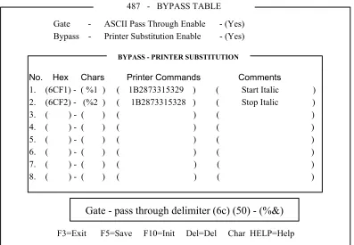
Printer Bypass Table
Allows the host application to transparently send controls commands to the attached ASCII printer, and enables special printer features such as bar-code.
Gate Table
The Gate feature is similar to Bypass feature, however, it
provides the capability to use unlimited number of printer codes.
Colored Terminals Capabilities
Supported colors
The LM-488C supports up to 16 colors, that can be chosen from a 64 color palette.
2. GETTING
STARTED
The IS-488 installation is designed to be simple and fast. Follow the instructions given below for selecting a location, unpacking and installing the workstation.
2.1
Selecting A Location
a. The area should be clean, free from shock and vibrations, extreme temperatures and high humidity.
b. The workstation should be placed on a flat surface.
c. The site should include a wall socket, incoming and outgoing Twinax cable (for additional workstations on the line).
d. Sufficient space should be left at the back of the workstation to allow free access to the connected cables.
e. The workstation should be connected directly to the wall socket, an not via an extension cable.
f. Make sure that the power source is +/-10% of rated power (either 115 or 220 VAC) and the frequency is 50/60 Hz +/- 2 Hz.
2.2 Unpacking
Instructions
Before opening the shipping package or the protective case, check to make sure that there is no visible external damage. If any such damage was incurred contact your distributor before opening the package.
Make sure that the following items have been included: 1. Keyboard: 122 or 102/103 keyboard
2. PS/2 mouse (option) 3. T-cable
4. Power cord 5. User’s Manual
Getting Started
2.3
Assembling the IS-488 Monochrome Workstation
To setup for the 14-inch monochrome monitor, DSM 1426, perform the following series of steps:
1. Place the monitor upside down on a flat surface.
2. Align the base with the slots in the underside of the and insert the Tilt/Swivel Base into the slots. Refer to the above figure.
3. Pull the Tilt/Swivel Base toward the front of the display until the hook clicks into the slot.
NOTE: To disconnect the base from the monitor, insert a screwdriver into the slot marked with an arrow in the above diagram, and depress the hook towards the front of the monitor.
Getting Started
4. Turn the assembled unit rightside up and connect the cables according to the following illustration:
1. Set the power switch on the monitor to OFF. 2. Face the back of the workstation.
3. Connect the keyboard cable to the keyboard port.
4. If a printer is to be installed, connect the printer cable to the printer port. 5. Connect the mouse (option) cable to the mouse port.
6. Connect the monitor interface cable to the monitor connector.
Getting Started
2.4
Assembling the LM-488C Color Workstation
An LM-488C workstation includes an SVGA color monitor which is assembled according to the manufacturer’s instructions.
NOTE: On an LM-488C workstation, the monitor power switch turns on the workstation.
1. Set the power switch to OFF. 2. Face the back of the workstation.
3. Connect the keyboard cable to the keyboard port.
4. If a printer is to be installed, connect the printer cable to the printer port. 5. Connect the mouse (option) cable to the mouse port.
6. Connect the monitor interface cable to the monitor connector in the box.
7. Connect the one power cable between the rear of the box and power outlet and the other between the rear of the monitor and the power outlet.
Getting Started
2.5
What to do Next ?
1. Power-ON the workstation.2. Perform the OFFLINE setup (chapter-3).
3. Power-OFF the workstation and connect the Twinax cable (section 2.6).
2.6
Connecting the Workstation to the Twinax Line
The following steps show how to connect the workstation to the Twinax line:CAUTION!!!
To avoid electrical shock, turn off the workstation and unplug it from the wall socket before you connect it to the Twinaxial line.
1. Make sure there are no users working on the specific line you are going to connect.
2. Connect the T cable to the appropriate connector on the rear of the workstation. Secure the T cable with two screws.
3. Connect the incoming cable to one of the sockets on the T cable. Connect the outgoing cable (if one exists) to the other socket.
4. If twisted pair cabling is used, then attach an RJ45 connector to the Twinax adapter and attach the adapter to one of the sockets on the T cable. Do not connect an adapter or Twinax cable to the other T-cable socket.
NOTE: The cable is equipped with a built-in terminator. This eliminates the need for a special terminator part for the last terminal on the line.
5. Connect the workstation to the power outlet.
6. Power on the workstation and wait until “SIGN ON SCREEN” appears on the display. If the screen does not appear, refer to Troubleshooting (Chapter-11).
Getting Started
2-6
2.7 Workstation
Maintenance
Regular cleaning and maintenance procedures are required to keep your workstation in good operating condition. It is recommended to clean the workstation regularly and make use of the screen saving options.
2.7.1 Cleaning the Workstation
Clean the screen surface with a soft, lint-free cloth, dampened with an ammonia or alcohol-based glass cleaner.
Alternatively, use a mild detergent solution in water as a glass cleaner, then wipe with a water-dampened cloth.
ATTENTION!!
Avoid the use of petroleum-based cleaners.
2.7.2 Screen Saver Option
The option is enabled in the Setup display of the Online Setup. Enabling this option prolongs CRT life.
It causes the screen to dim automatically if for a preset time (5 to 20 minutes), no key is pressed or there is no host command input. An indicator will appear on the status line indicating that the screen has been dimmed. To display is restored when a key is pressed.
2.7.3 Power Saver
This is a built-in function to save power. If the workstation is ON and not active (i.e. no
keyboard or host input) for more than two hours the screen dims indicating that the power saver function is enabled.
Power consumption is reduced by up to 50% and emission of radiation from the workstation is also greatly reduced.
3. OFFLINE
SETUP
Offline setup allows you to configure the following: number of sessions and their addresses, display character set, printer address and emulation, type of ASCII printer, printer symbol code page and workstation language. In addition, the offline setup defines the display sessions model ID and alternate addresses.
The default parameters for all the offline setup screens are given in Appendix-A.
IMPORTANT !!!
Perform the offline setup before connecting the workstation to the Twinax line.
3.1 Overview
3.1.1 Entering Offline Setup
1. Power-on the workstation (turn the switch on the electronics box ON) and keep the Spacebar pressed during initialization.
2. An indicator light (on the monitor or box depending on the type of workstation) will be turned on and within a few seconds the Offline Setup screen will be displayed:
Offline Setup More+
Move cursor to desired selection and press ENTER.
Customize Workstation Update Serial Number Test Workstation
F3=Exit Version xxxx
SETUP
Parameter Definitions:
Customize Workstation Provides access to screens for configuring the number of sessions, their type and addresses, in addition to defining the character sets and language definitions.
Update Serial Number Enables you to set the workstation serial number.
Offline Setup
3.1.2 OFFLINE Setup Function Keys and Indicators
Key or indicator Description
F7 Page backward
F8 Page forward
F3 Save changes and exit to the Offline Main setup screen. More+ indicator on the top
right corner.
Additional configuration screens for that option.
More- indicator on the top right corner.
Last configuration screen for that option.
To define a parameter Place the cursor on the desired value and press the
Spacebar. The defined parameter value will be highlighted. Exiting Offline Setup Mode Press F3
3.2
Offline Customization Setup
3.2.1 Defining Sessions, Addresses and Modes
The workstation supports up to four sessions and an additional printer session. You may assign each session a unique address, or select one address to be shared by all the defined sessions (not including the printer).
To enter the screen
From the Offline Setup menu, select Customize Workstation and press Enter. The following screen will appear.
Customization More+
Move cursor to desired selection and press SPACEBAR to select.
Dislay Sessions... 1 2 3 4 Printer Sessions ... Yes No
Shared Addressing ... Yes No
Display Address 1... 0 1 2 3 4 5 6 Display Address 2... 0 1 2 3 4 5 6 Display Address 3... 0 1 2 3 4 5 6 Display Address 4... 0 1 2 3 4 5 6 Character Set ... Country Specific Multinational
Printer Address... 0 1 2 3 4 5 6 Printer Emulation ... 5256 5214 5219 3812
F3=Exit F8=Forward T=ASCII B=Bypass SETUP
Offline Setup
This screen allows you to define the number of sessions, session addresses and character sets. In addition, the printer session is enabled and defined in this screen. Enabling the printer sessions option, displays the printer related parameters such as emulation type and address.
The various options are described in the following sub-sections.
3.2.1.1 Display Sessions
Sets the Number of Display Sessions supported by the workstation.Value = 1 to 4
3.2.1.2 Printer Sessions
Enables a printer session. The printer is directly connected to the display station and acts as a host printer.Enabling this parameter (Yes), activates the printer address and Printer emulation mode which must be defined as well.
In addition, you may access the Printer EBCIDIC to ASCII translation table by pressing T, and the Bypass Table by pressing B. These functions are described in chapter 6.
A “Help” screen is provided by pressing Help while displaying either EBCIDIC or Bypass screen.
3.2.1.3 Shared Addressing
Each of the assigned terminal addresses may be defined as a shared address and used by all the terminal sessions. Sessions sharing a single address are independent of each other. The host andapplication must support shared addressing for this function to work.
Device addresses should be provided by the System Manager.
Offline Setup
3.2.1.4 Display Address 1 to 4
The unique host connection address for each defined display station 1 to 4 (depending on the number of enabled sessions).The address is defined as ‘occupied’ by an ‘asterisk’ to all other sessions addresses including that of the printer.
A maximum of 7 addresses are available per port, enabling the user to connect sessions of more than one display station to a port. Up the 28 sessions can be assigned to each port when shared addressing is enabled.
3.2.1.5 Printer Address
The unique host connection address for the printer. The address is defined as ‘occupied’ by an ‘asterisk’ to all other sessions addresses including that of the printer.Value: 0 to 7
3.2.1.6 Character Set
The character set used by the workstation. Multinational: A standard set of multinational characters.Country Specific: A character set specific for your country. The character set and language used on your workstation, is selected in the Country Specific screen.
3.2.1.7 Printer Emulation
Four Printer Emulation options are available: 5256; 4214; 5219; 3812Refer to the tables in Appendix-B to select the appropriate printer emulation (listed in descending order of preference).
Offline Setup
3.2.2 ASCII Printer Model Type
This screen enables you to define the printer emulation mode and character code.
To enter the screen
From the Offline Setup menu, select Customize Workstation and page forward until the following screen is displayed.
Customization Move cursor to desired choice, then press SPACE BAR to select. Printer Model/Type
Nulldriver Other Postscript Canon LBP
Canon-BJ330 Diablo-630 Epson-JX80 Epson-FX286
Epson-FX1050 Epson-LQ1500 Epson-LQ1000 Epson-LQ2550
Epson-LQ1170 HP-Thinkjet HP-RugWtr HP-Deskjet500
HP-LaserjetII HP-LJ2-Offset HP-Laserjet3/4/5 IBM-PcGr-5150
IBM-ProXL IBM-XL24-4207/8 IBM-Quickwtr-5204 IBM-4019
IBM-2381 IBM-2391 IBM-4072 IBM-PPDS
Ithaca-PcOS-S.50 NEC-P5/6/7 NEC-P9300 OKI293
OKI321S OKI 393M Panasonic-1624 Panasonic-1695
Qume-S-11P Star 1520 Toshiba-3X1S Boca
Symbol Code Page
ASCII 437 ECMA-94 Roman-8
850 DL-IBM-Pro-9 DL-Epson-9
F3=Save and Exit F7=Backward F8=Forward E=Editor
SETUP
Define the parameters according to the explanations given below.
3.2.2.1 Printer Model/Type
Type of printer or printer emulation.Offline Setup
3.2.2.2 Symbol Code Page
Defines the printer character set as follows:ASCII 7-bit character set.
437 Also referred to as IBM Character Set 2.
ECMA-94 European Standard.
850 IBM Standard providing the complete range of accented alpha characters required for
international language support.
Roman-8 Hewlett-Packard Roman 8 character set with Roman 8 symbol extension.
DL-IBM Character set downloaded to the Proprinter printer by the workstation via the escape strings which are specifically formatted for the Proprinter XL. These
escape strings set up the dot patterns for the character set. The set formed in this way is equivalent to the 850 set.
DL Epson 9 Downloaded to the printer by the workstation via escape strings which are specifically formatted for the Epson FX series of printers.
The set formed in this way is equivalent to the 850 set.
Offline Setup
3.2.3 Keyboard And Country
This screen enables you to define the type of keyboard and language used on the workstation.
To enter the screen
Select Customize Workstation from the Offline Setup menu and page forward until the following screen is displayed.
3.2.3.1 Keyboard Type
Type of keyboard installed on the workstation. Standard keyboard: Assigns a standard keyboard configuration.User Defined: Selecting this option enables the Keyboard ID options from which you can select the keyboard.
Keyboard ID: A number representing a user defined keyboard.
Offline Setup
3.2.4 ASCII Printer Type
This screen allows you to define either a standard ASCII printer type or a user defined printer. In addition this screen defines the start position corresponding to the Paste command.
To enter the screen
Select Customize Workstation from the Offline Setup menu and page forward until the following screen is displayed.
3.2.4.1 ASCII Printer Type
Defines the type of printer connected to the workstation. Standard: A standard printerUser Defined: Enables the selection of an ASCII Printer ID for downloading a PDT (Printer Definition Table) identified by the selected ASCII printer ID from the AS/400. Your System Manager can help select the correct option.
ASCII Printer ID: This field represents the ID of a PDT downloaded from the AS/400.
3.2.4.2 Paste Start Position
This option defines the starting position where copied data will be pasted (chapter-8).Text cursor: Pastes the data according to the position of the Text Cursor.
Mouse Pointer: Pastes the data according to the position of the Mouse Pointer.
Offline Setup
.
3.2.5 Alternate Addresses for Display Sessions
This screen enables you to define the alternate addresses for each session.
To enter this screen
Select Customize Workstation from the Offline setup menu, and page forward until the following screen is displayed.
CUSTOMIZATION More+
Move cursor to desired selection and press SPACEBAR to select.
Alternate addresses for Session 1
Alt Address 1... 0 1 2 3 4 5 6 No Alt Address 2... 0 1 2 3 4 5 6 No Alt Address 3... 0 1 2 3 4 5 6 No Alt Address 4... 0 1 2 3 4 5 6 No Alternate addresses for Session 2
Alt Address 1... 0 1 2 3 4 5 6 No Alt Address 2... 0 1 2 3 4 5 6 No Alt Address 3... 0 1 2 3 4 5 6 No Alt Address 4... 0 1 2 3 4 5 6 No Alternate addresses for Session 3
Alt Address 1... 0 1 2 3 4 5 6 No Alt Address 2... 0 1 2 3 4 5 6 No Alt Address 3... 0 1 2 3 4 5 6 No Alt Address 4... 0 1 2 3 4 5 6 No
F3=Save and Exit F7=Backward SETUP
3.2.5.1 Alternate addresses
After power up, the Workstation will test the line to check for busy addresses.If the address defined in Setup is occupied by another workstation, this terminal will set the station address to the first “not busy” address from the alternate list.
Offline Setup
3.2.6 Model ID and Alternate Addresses for the Printer Session
This screen enables you to define the Model ID and alternate address for the printer session and for display session-4.
To enter this screen
Select Customize Workstation from the Offline setup menu, and page forward until the following screen is displayed.
NOTE: This is the last screen in the Customization menu. Press F3 to return to the Main offline setup menu where you may select the next option.
Customization More-
Move cursor to desired selection and press SPACEBAR to select.
Model ID ... 3487 3197C 3197D 3180 5291
Alternate addresses for Session 4
Alt Address 1 ... 0 1 2 3 4 5 6 No Alt Address 2 ... 0 1 2 3 4 5 6 No Alt Address 3 ... 0 1 2 3 4 5 6 No Alt Address 4 ... 0 1 2 3 4 5 6 No Alternate Addresses for Printer
Alt Address 1 ... 0 1 2 3 4 5 6 No Alt Address 2 ... 0 1 2 3 4 5 6 No Alt Address 3 ... 0 1 2 3 4 5 6 No Alt Address 4 ... 0 1 2 3 4 5 6 No
F3=Exit F8=Forward SETUP
3.2.6.1 Model Id
If connected to: Define the workstation as:AS/400 3487, 3197C, 3197D, 3180, 5291
System 36; 3197C, 3197D, 3180, 5291
System 38; 3180, 5291
NOTE: Select 5291 if the workstation is connected to an old controller since these support only Model ID 5291 and a 122-key keyboards.
3.2.6.2 Alternate
Addresses
Up to four alternate addresses can be defined for display sessions and the printer.
Selecting No disables this function.
Offline Setup
3.3 Serial
Number
This screen allows you to enter the number used for network control, workstation manufacturing plant and the machine serial number printed on the label located at the underside of the Logic Box.
To enter this screen
Select UpdateSerial Number from the Offline setup menu, press enter.
3.3.1.1 Plant of manufacture
Select a character from each row. The corresponding characters will be highlighted in the Machine Serial field.3.3.1.2 Serial number
This is the number used for network control.Offline Setup
3.4 Test
Menu
This menu is used for testing various options and resetting to factory defined values.
To enter this screen
Select Test Workstation from the Offline setup menu and press enter. The following screen will be displayed. Select and enter each option to be tested.
NOTE: You may set the Factory Defaults and the Record/Play options. It is recommended that all the other test options are used only by service personnel.
3.4.1 Set Factory Defaults
This screen enables you to reset or clear the following parameters: Addresses, system printer emulation, printer model/type, code page, display language, keyboard mapper, as well as gate codes, bypass codes and record/play keys.
1. Press Enter. Respond with Yes to the verification message “Are you sure (Y/N)?” 2. The message “Restoring Factory Defaults, Please Wait.”, will be displayed.
Offline Setup
3.4.2 Record/Play Options
The Record/Play Options panel with the following three options will be displayed:
R0 - The full record/Play function is available.
R1 - Non display input is prohibited.
R2* - The Record/Play function is disabled.
*IMPORTANT!! If you select R2, the Record/Play option can only be re-enabled by a company representative.
The Record/Play function is fully described in Chapter-6.
3.4.3 Display Attributes
The Attribute screen will display.
The following six attributes are shown on screen:
For monochrome monitors: NORMAL; COLUMN SEP; REVERSE; BLINK; HIGH INTENS; UNDERSCORE
For color monitors: Seven color attributes.
3.4.4 Display Char Set
This option enables you to display the character sets for all the following models: • 80 columns x 25 rows
Offline Setup
To display the character set
1. Select Display Char Set from the Test menu.
2. Press Enter to display the first character set, and the Spacebar to view other sets. 3. Press F3 to exit to the Test menu.
3.4.5 Display Version
This screen displays the workstation version.
1. Select Display Version from the Test menu. 2. Press Enter to display the workstation version. 3. Press F3 to exit to the Test menu.
3.4.6 Twinax Line Test
This screen enables the initiation of a Line test. The online test is performed continually and updates its status continually until it is terminated (by pressing F3).
1. Select Twinax Line Test from the Test menu. 2. Press Enter to initiate the test.
Device addresses from 0 to 6 are listed and their status determined. A blinking Line Testing... message appears at the bottom of the screen.
* will appear bellow each listed address of a device that is communicating with the host controller.
= will appear bellow each listed address of a device that is not present on the system or which did not communicate with the host controller.
- will appear bellow each listed address of a device that the host controller did not attempt to communicate with (Polling).
3. Press F3 to exit to the Test menu.
Offline Setup
The test is being continuously performed, that is to say, if the status of any device on the line, or the status of the line itself changes, after a few seconds the status message on the screen will change accordingly.
The addresses of the devices are the addresses set in the SETUP as the address of the workstation/printer, with no relation to the logic address defined on the computer, such as P1, W12, etc.
3.4.7 Keyboard Test
Enables the Keyboard Test screen.
1. Select Keyboard Test from the Test menu. 2. Press Enter to display the keyboard test screen.
3. A keyboard map is displayed. When a key is depressed, the parallel key on the screen is highlighted.
4. Press F3 to exit to the Test menu.
3.4.8 Printer Test
Enables the test screen for a parallel printer. 1. Select Printer Test from the Test menu. 2. Press Enter to display the printer test screen. 3. Press Enter to initiate the test.
Offline Setup
3.4.9 Monitor Test
Enables the Monitor Test screen.
1. Select Monitor Test from the Test menu. 2. Press Enter to display the Monitor test screen.
MONITOR TEST
Press ENTER to start testing, then press one of the following keys:
F8 for next test F3 to Exit
F9 Reverse Video toggle test F4 Power Saver Toggle Test F5 Horizontal Sync Toggle Test F6 Verticall Sync Toggle Test
F7 Horizontal and Vertical Sync Toggle Test
TEST
3. Press Enter to display the first screen model. If it is not the required model, press the Spacebar to page through all the other available models.
4. Once the desired model is displayed, perform the display test according to the following table, pressing the same key again to end the specific test:
Key Test
F9 Reverse Video Toggle test (Monochrome Display Only) F4 Power saver test
F5 Horizontal Sync test F6 Vertical Sync test
F7 Horizontal and Vertical Sync test
5. Press F8 to access the following pattern and repeat step-3. 6. Press F3 to exit to the Test menu.
Offline Setup
3.4.10 Scroll Test
Enables the Scroll Test screen.
1. Select Scroll Test from the Test menu.
2. Press Enter to enter the test which displays a continually rolling screen. 3. Press F3 to exit to the Test menu.
3.4.11 Mouse Test (for PS/2 mouse)
Enables the Mouse Test screen.
1. Select Mouse Test from the Test menu, and press Enter. 2. Press Enter to enter the test.
Moving the mouse in any direction will cause a similar movement of the mouse icon on the display. Clicking either mouse button will highlight the parallel button on the screen
simulation.
3. Press F3 to exit to the Test menu.
3.4.12 Keyboard Mapper
This option enables the redefinition of a key function.
To enter the test
Select Keyboard Mapper from the Test menu and press Enter.
To Map a Key
1. Select the key to be redefined (i.e. F12). The corresponding key on the screen will be highlighted.
2. Press the Record key on the keyboard
3. Press the key (ie. Dup PA1).whose function is to be transferred to the first key (F12).
4. Repeat steps 1 to 3 for any additional keys.
5. To exit after mapping your selected keys, press Reset.
6. To activate the keyboard mapper press the Setup key to enter OnlineSetup.
7. Choose SetupDisplay. Press Enter.
8. Move cursor to EnableKeyboardMapper, highlight YES and press the Space bar.
Offline Setup
3-18
To Clear All Mapped Keys:
1. Enter Offline Setup. (turn the workstation ON while depressing the Space bar.)
2. Select Test Workstation. Press Enter.
3. Select Keyboard Mapper and press Enter. Press Alt + F1 to clear all mapped keys and return the keyboard to the factory preset conditions.
4.
ONLINE SETUP MENU
Online setup enables you to set or reset some of the Workstation’s features at any time during operation. It also enables you to view what values have been selected in Offline Setup. Online Setup can be accessed at any time during a work session.
This chapter will provide a brief description of the options available in the online setup menu.
4.1 Overview
4.1.1 Entering Online setup menu
Power on the workstation, wait for the initialization to be completed and press the Setup key. The Online Setup menu will be displayed.
Online Setup Move cursor to desired selection and press ENTER.
Setup Display
Browse Display Information Setup Printer
Browse Printer Information Setup Input Devices Setup calculator Lock Sessions Setup color
F3=Exit SETUP
Parameter Description
Setup Display Defines the display mode
Browse Display Information Provides a summary of the sessions, addresses,
emulation mode, character sets and keyboard definitions set in the Offline setup (chapter 3).
Setup Printer Defines the printed density of lines and characters as well as printing resolution.
Browse Printer Information Provides a summary of the printer address, emulation mode, paper related options.
Online setup menu
Parameter Description
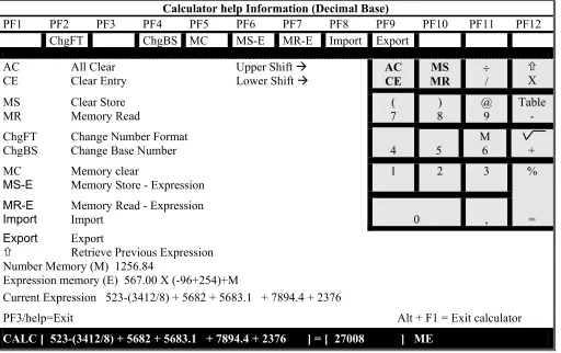
Setup calculator Defines the calculator decimal point as either a period or a comma.
Lock Sessions Enables you to define a security password for the workstation.
Setup color Enables you to select the 16 color palette and define session and screen border colors, mouse pointer and ruler colors.
4.1.2 ONLINE Setup Function Keys and Indicators
Key or indicator Description
F7 Page backward
F8 Page forward
F3 Save changes and exit to the Offline Main setup screen.
More+ indicator on the top right corner.
Additional configuration screens for that option.
More- indicator on the top right corner.
Last configuration screen for that option.
To define a parameter Place the cursor on the desired value and press the Spacebar.
Exiting Online Setup
Mode Press F3 or Setup (for 122 keyboard)
Press F3 or Shift +Setup (for 103 and PC keyboards)
Online setup menu
4.2 Setup
Display
This menu group customizes the appearance of the screen (i.e. cursor style, split screen format, etc. ) and some responses (auto dim, password, etc.). The options are located on four consecutive screens which will be described in this section in the order in which they appear.
NOTE: Press F8 to access consecutive screens and F7 to return to previous screens.
4.2.1 Setup Display Screen-1
This screen defines the alarm, cursor, screen indicator and ruler. In addition it enables the screen dimmer and keyboard mapper options.
To Enter this screen
Select Setup Display Information from the Online Setup menu. Press F8 to access the following screen.
4.2.1.1 Alarm Volume Set the workstation’s alarm to any one of five different intensity levels, or turn it off.
Online setup menu
4.2.1.3 Row/Column Indicator If ON is selected, the line and column number on which the cursor is currently located are indicated at the bottom right corner of the screen.
4.2.1.4 Rule Line A horizontal and/or vertical line displayed on the screen, which enables easy editing of large columns/rows. Style: Horizontal, Vertical or both (cross). Intensify (monochrome models only): Determines whether the Rule Line appears bold or normal. Follows cursor: Determines if the Rule Line will move with the cursor or remains a static marker on the screen.
4.2.1.5 Auto Dim When selected, the screen will blank out if no input has been entered for a predefined period of time (Delay) of 5, 10 or 20 minutes.
4.2.1.6 Enable Keyboard Mapper Enables the Keyboard Mapper.
Online setup menu
4.2.2 Setup Display Screen-2
This screen defines the display format, buzzer time and column separators. To access this screen
Select Setup Display Information from the Online Setup menu and page forward.
Setup Display More+
Move cursor to desired selection and press SPACEBAR to select.
Extended Dislay ... Off PS ECB1
ECB2 ECB3
Split Screen Format (Screen rows X columns)
Horizontal ... 24 X 80 32 X 80 43 X 80 49 X 80 Vertical ... 24 X 80 27 X 132
Buzzer Time ... 0.4 0.6 0.8 1.0 1.2 1.4 ... 1.6 1.8 2.0
Separator... Yes No Column Sep... Dot Line
F3=Save and Exit F8=Forward F7=Backward SETUP
4.2.2.1 Extended Display PS, ECB1, ECB2 and ECB3 enable the display of attributes in the Presentation Space, primary ECB (ECB1), text ECB (ECB2) or color ECB (ECB3). OFF displays text normally. 4.2.2.2 Split Screen Determines the mode of the split screen when viewing two
sessions.
4.2.2.3 Buzzer Time Duration of the buzzer sound may be programmed from 0.4 to 2.0 seconds in 0.2 second steps.
4.2.2.4 Separator Enables a separation line between screen and status line. 4.2.2.5 Column Sep Defines the appearance of the columns separator.
4.2.2.6 Reverse Image For monochrome only. Provides a negative of the screen. NO: Black characters on a white background
Online setup menu
4.2.3 Setup Display Screen-3
This screen defines the editing functions such as tabs, type ahead and cut-and-paste. To access this screen
Select Setup Display Information from the Online Setup menu and page forward.
Setup Display More+
Move cursor to desired selection and press SPACEBAR to select.
Local Tabs Yes No
Type Ahead ... Yes No Message Wait ... Off Beep Video Dual 132 ... Yes No Local Cut&Paste Enable ... Yes No
F3=Save and Exit F8=Forward F7=Backward SETUP
4.2.3.1 Local Tabs Enables local tabs that allow the user to advance the cursor from column to column on a screen.
4.2.3.2 Type Ahead Enabling this feature allows you to keep on typing even though “Input Inhibited” indicator is lit. Data will be transmitted to the host controller as soon as the “Input Inhibited” indicator goes off. Data quantity is dependent on the host controller.
4.2.3.3 Message Wait Enables an Indicator/Reminder that a unit in the system needs corrective action. Two kinds of indicators are available:
Beep: Enables the a buzzer that goes off every 8 seconds. Video: The screen display is inverted every 8 seconds.
4.2.3.4 Dual 132 Displays two session in horizontal split mode even if one of them is altered to 132 character mode.
Yes: Two session, one in 80 character mode and the other in 132 character mode.
No: When one session is in 132 character mode, both sessions cannot be seen simultaneously in horizontal split.
4.2.3.5 Local Cut and Paste
Enables cut and paste options. Yes: Enables local cut-and-paste. No: Disables local cut-and-paste.
Online setup menu
4.2.4 Setup Display Screen-4
This screen defines the password used when the screen is locked (by selecting Lock Sessions from the Online Setup menu).
To access this screen
Select Setup Display Information from the Online Setup menu and page forward.
Online Setup More+
Specify pasword twice and press ENTER
Lock Sessions
Password ... (_________) Password ... (_________)
F3=Save and Exit F7=Backward F10=Clear Password SETUP
4.2.4.1 Lock Sessions Password
Defines the password used when the screen is locked. To enter the password
Enter a password consisting of 5 alphanumeric characters and press Enter. Repeat for the second field.
Online setup menu
4.3
Browse Display Information
Provides a summary of the sessions, addresses, emulation mode, character sets and keyboard definitions set in the offline setup (chapter 3). In addition, this screen displays the software version.
NOTE: The information in this screen cannot be modified.
To Enter this screen
Select Browse Display Information from the Online Setup menu.
Display Information
Display Sessions... 1 2 3 Shared addressing... Yes No
Display Address 1 ... 0 1 2 3 4 5 6
Display Address 2 ... 0 1 2 3 4 5 6
Display Address 3 ... 0 1 2 3 4 5 6
Display address 4... 0 1 2 3 4 5 6
Character Set... Country Specific Multinational
Keyboard Type ... Standard User Defined Model ID ... 3487 3197D 3197C 3180 5291
Country ... Belgium Denmark Finland/Sweden
France Germany/Austria Greece
Holland Iceland Italy
Norway Portugal-037 Portugal-282
Spain Spain, L/A Swiss (France) Swiss (Germany) Turkey-905 UK
US/Canada Turkey-1026 France/Canada
Latin 2 Poland Hungary
F3=Exit Release No 1.0
SETUP
Online setup menu
4.4 Setup
Printer
The Setup Printer menu consists of up to five screens that allow you to define all printer related options.
4.4.1 Setup Printer Screen-1
This screen enables you to define the print density on the page.
To access this screen
Select Setup Printer from the Online Setup menu.
4.4.1.1 Lines per Inch Set the printed lines per inch to either System, in which the setting is controlled by the host or 3, 4, 6, or 8 LPI (Lines Per Inch).
4.4.1.2 Characters Per Inch Set the number of characters per inch to either System (host controlled), 5, 10, 12 CPI (Characters Per Inch) or Compressed. The default setting is ‘10’.
4.4.1.3 Print Quality The print quality may be selected in three levels: System (host controlled), Draft, or NLQ.
Print speeds are reduced when higher print qualities are selected.
Online setup menu
4.4.1.4 Printer Key Function
To Press
Resets the parallel port Printer. F1=Reset Sends a Form Feed to the parallel
port printer.
F2=Form Feed
Sends a Line Feed to the Parallel port printer.
F4=Line Feed
Sends a Cancel request to the Host. F5=Cancel
4.4.2 Setup Printer Screen-2 (5219 & 3812 Emulations Only)
This screen enables you to select the type style and paper related options.
To Enter this screen
Select Setup Printer from the Online Setup menu and page forward.
4.4.2.1 Type Style Type Style determines the typeface which will be used while printing. It may be set to System (host controlled), or (locally controlled).
4.4.2.2 System Code Page If set to System, the Code page designated by host is applied to the printer.
If set to Local, the Code page selected on the Local printer is applied.
4.4.2.3 Paper Feed Determines how the paper feed is controlled. System: Controlled by host.
Online setup menu
Pause: Temporarily suspends operation until the
appropriate action is taken according to system message. Operation is then resumed.
Local: Controlled locally.
4.4.2.4 Source Drawer Specifies the location of the paper in the printer. System: Paper location is determined by the host. Pause: Temporarily suspends operation until the
appropriate action is taken according to system message. Operation is then resumed.
1 : The first paper bin is selected. 2 : The second paper bin is selected.
Fixed: According to the configuration on the printer.
4.4.2.5 Form The format of the paper. System: Host controlled.
Pause: Temporarily suspends operation until the
appropriate action is taken according to system message. Operation is then resumed.
Paper: Printing on paper. Envelope: Printing on envelopes.
4.4.2.6 Attention Warning of a change in some printing parameters such page or font definitions. Printing is resumed only after there is a response to this prompt.
Online setup menu
4.4.3 Setup Printer Screen-3 (for 3812 Emulation only)
These additional parameters are optional and are displayed only if 3812 printer emulation was selected in the Offline Setup Customization panel. It enables the selection and orientation of paper in each of the three ‘Drawers’.
To enter this screen
Select Setup Printer from the Online Setup menu and page forward.
4.4.3.1 Default Orientation:
Select COR, Portrait or Landscape for each of sources.
This parameter is effective only on a printer that has the capability of rotating the paper (3812 emulation must be selected).
4.4.3.2 Paper: Seven paper sizes are available for selection. This parameter determines whether the paper will be rotated for the COR option in Default Orientation as well as for the Automatic Orientation
function. 4.4.3.3 Automatic
Orientation:
Set to YES for automatic orientation selection by the workstation according to the printing job.
Online setup menu
4.4.4 Setup Printer Screen-4
This screen will display for any printer emulation selected in Offline setup.
To enter this screen
Select Setup Printer from the Online Setup menu and page forward.
Setup Printer
Move cursor to desired choice, then press SPACE BAR to select.
Print Key... Local System Local Form Feed... Yes No Local Condensed... Yes No Buffer Print... Yes No Hex Print... Yes No
F1=Reset F2=Form Feed F4=Line Feed F5=Cancel F3=Save and exit F7=Backward F8=Forward
SETUP
4.4.4.1 Print Key The printer that responds to the Print Screen command is either the Local screen printer which is attached to the display station or the System printer.
Local: Allows you to define the region on the screen and print it locally.
System: Sends the print request to be printed by the host.
4.4.4.2 Local Form Feed
When using the local print option (screen copy), enabling this option performs automatic Form Feed after screen dump. Page ejection may be selected at the ending of local screen print.
4.4.4.3 Local Condensed
Enables you to print a document without the blank lines. Yes: Will not print blank lines (condensed).
No: Blank lines will be printed.
4.4.4.4 Buffer Print Buffer print contains EBCDIC Hexadecimal codes which can be used by technicians for troubleshooting application programs.
YES: Enables buffer print. Not: Disables buffer print.
Online setup menu
printer.
Yes: Enables Hex print. No: Disables Hex print. .
4.4.5 Screen Print Setup
The necessary parameters for a screen print are set here.
To enter this screen
Select Setup Printer from the Online Setup menu and page forward to the last screen.
4.4.5.1 Lines Per Inch Defines the line density for a local screen print job. Value = 3,4,6,8 lines per inch (LPI).
4.4.5.2 Characters Per Inch
Defines the character density for a local print job.
Value = 5, 10, 12 or compressed (blank lines are not printed). 4.4.5.3 Print Quality Defines the print quality.
Value = Draft or Near Letter Quality 4.4.5.4 6.12.4 Source
Drawer
Enables selection of paper from Drawer 1 or Drawer 2. Fixed indicates that no attempt at all should be made to specify a drawer.
4.4.5.5 Form Length In Inches
Maximum value = 24 inches. To change a form length:
Online setup menu
1. Press the Spacebar to enter Edit mode.
2. To exit Edit mode press the Up or Down arrow keys. NOTE: Automatically changes the Form Length In Millimeters parameter to the corresponding value.
4.4.5.6 Form Length In Millimeters
Maximum form length value = 609.60 millimeters. To change a form length:
1. Press the Spacebar to enter Edit mode.
2. To exit Edit mode press the Up or Down arrow keys. NOTE: Automatically changes the Form Length In Inches parameter to the corresponding value.
4.4.5.7 First Print Line Specifies the line on which the next screen print operation should begin.
To change the value:
1. Press the Spacebar to enter Edit mode.
2. To exit Edit mode press the Up or Down arrow keys. NOTE: If a line which is beyond the specified form length is specified, then unpredictable results can occur.
4.4.5.8 Print First Column Specifies the column on which each line of the screen print will start:
To change the value:
1. Press the Spacebar to enter Edit mode.
2. To exit Edit mode press the Up or Down arrow keys.
Online setup menu
4.5
Browse Printer Information
Provides a summary of the printer information and customization options. An example is given following the explanations on the screen.
To enter this screen
Select Browse Printer Information from the Online Setup menu and page forward to the last screen.
Printer parameters selected in Setup are highlighted for each of the above settings. The selected parameters cannot be changed in this panel.
Type Style, System Code Page, Paper Feed, Form, Source Drawer and the option F2=Resume are displayed only if 3812 or 5219 printer emulation option has been selected in the Offline Setup Customization screen.
When the following four conditions are selected simultaneously, the host can suspend the print operation and display the request for changing the current type style, system code page, paper feed technique, form or source drawer on the 22nd line of the Printer Information panel.
• Display-Printer terminal mode • 3812 or 5219 emulation type
• Setup Printer panel, Attention is enabled.
• Any of the following five setup printer parameters are set to System: • System code page,
• Type style, • Paper feed, • Form, and • Source drawer
Online setup menu
4.5.1.1 Example
Assuming that a host system requests a type style change from 011 Courier 10 specified in the Printer Information screen, to 087 Letter Gothic, and the other items are unchanged, the type style on the Printer Information screen will automatically change to 087 Letter Gothic, and the change request will be displayed at the bottom of the screen.
If the font cartridge on the attached printer does not include 087 Letter Gothic, change it to one that does, and then press ’. The print operation with the type style will start. If the requested cartridge is not available, press ’ to ignore the host request.
For detailed information on how to change the type style, system code page, paper feed mechanism, form type, or source drawer type, refer to your printer’s Operation Manual. If you do not want the print operation to be suspended by the host system, select No for the Attention parameter in the Setup Printer screen.
If the printer is printing data when it receives a request for changing the type style, system code page, paper feed mechanism, form type, or source drawer, the data transmission from the workstation to the printer will be immediately suspended but the printer may continue printing data stored in the print buffer.
Online setup menu
4.6
Setup Input Devices
Enables keyboard and mouse related such as sound and response speed.
4.6.1 Setup Input Devices Screen-1
To enter this screen
Select Setup Input Devices from the Online Setup menu.
Setup Input Devices More:+
Move Cursor to desired choice, then press SPACE BAR to select.
Clicker
Click...Yes No
Volume ...Off 1 2 3 4 High
Keyboard Typematic
Rate ...Slow Normal Fast Delay...Short Normal Long
Mouse Speed
Horizontal...Slow 1 2 3 Fast Vertical ...Slow 1 2 3 Fast
Mouse Double Click
Interval (seconds)...0.25 0.5 0.75 1.0 2.0
Mouse Primary Button...Left Right
Mouse Hot Spot...Yes No
F3=Save and Exit SETUP
4.6.1.1 Clicker Clicker: Enables the keyboard click sound.
Volume: Sets the click sound intensity at levels 1 - 4, Off or On.
4.6.1.2 Keyboard Typematic
Rate: Typing speed for repeated keying. E.g. when a key is pressed and held down. Three speed options are available: Slow, Normal and Fast.
Delay: Time interval from pressing the key until it starts repeating.
4.6.1.3 Mouse Speed Horizontal: Changes the Horizontal speed of the mouse pointer on the screen. Five settings are available: Slow, 1, 2, 3 and Fast. Vertical: Changes the Vertical speed of the mouse pointer on the screen. Five settings are available: Slow, 1, 2, 3 and Fast. NOTE: This parameter will be displayed only if a PS/2 mouse is
Online setup menu
attached to the workstation. 4.6.1.4 Mouse
Double Click
Interval: Sets the Double Click Interval within 0.25, 0.5, 0.75, 1.0 or 2.0 sec.
4.6.2 Setup Input Devices Screen-2
Defines the mouse Primary button. This option can be used by left handed people to define the primary button as Left.
To enter this screen
Select Setup Input Devices from the Online Setup menu and page forward.
4.6.2.1 Mouse Primary Button Left: Sets the Left button of the mouse as the main button.
Right: Sets the Right button of the mouse as the main button
Online setup menu
4.7 Calculator
Setup
Defines the calculator decimal point as either a period or a comma. To enter this screen
Select Setup Calculator from the Online Setup menu.
4.7.1.1 Decimal Point Period: Sets the decimal point as a period .. Comma: Sets the decimal point as a comma
4.8 Lock
Sessions
This screen enables you to lock a session if a password has been assigned, or assign a password and then lock the session.
To lock a sessions
1. Select Lock Session from the Online Setup menu.
2. If a password has not been set, the Lock sessions password screen will be displayed. Assign a password (enter up to five character password twice, pressing Enter each time). 3. The screen will now be locked.
To unlock a session
1. Press any key and enter the password.
2. If the workstation is locked and you do not know the password and want to change it then turn off the workstation, wait ten seconds, then turn on the workstation. Now follow the procedure in To set the password.
Online setup menu
4.9 Setup
Color
This screen enables you to uniquely identify each defined session with a background color and define the color of the screen border.
To access the screen
Select the Setup Color from the Online Setup Menu:
SETUP COLOR PALETTS More+ Move cursor to desired selection and press SPACEBAR to select.
Setup color Palette
Background Session 1 Background Session 2 Background Session 3 Background Session 4 Background Inactive Screen Border
Trim Border/ruler Line Mouse Pointer Status Line
F3=Exit F8=Forward
SETUP
Online setup menu
4-22
Background Session 1 to 4 • Sets the background color of each session in its active state. It is recommended to select a dull color (i.e.olive).
Background Inactive • Sets the background color for the inactive session. ‘black’ is the default setting.
Screen Border • Sets the color of the screen border.
Trim Border/ruler line • Sets the color of the ruler, trim line, push button and status line separator.
Mouse Pointer • Sets the color of the mouse pointer
1. Select an option and press the Spacebar.
2. Upon pressing the Spacebar, a color palette will be displayed. Use the Arrow keys to choose the desired color and press the Spacebar to enable the selection. Refer to the following section for instructions on redefining the color palette.
3. To define a black background color, selecting the color and press the Spacebar again. 4. Repeat steps 1 to 2 for each option.
4.9.1 Customizing the Foreground and Background Color Palettes
This option enables you to define the colors on your color palette.
1. Page forward (F8) from the Setup Color screen, to display the Setup Background Color Palette screen. The assigned colors are displayed above the color bars.
2. Use the left and right Arrow keys to move the cursor to the desired color bar. 3. Press the Spacebar to mark the bar with two arrow.
4. Use the up and down arrow keys to select the desired shade and press the Spacebar to enable the selection.
5. Repeat steps 2 to 4 for every color you wish to assign to the color palette. 6. Press F8 to display the Setup Foreground Color Palette
7. Repeat steps 2-4 for every color you wish to assign to the Foreground Color Palette. 8. Press F7 to return to the Color Setup screen, or F3 to return to the Online main setup
menu.
9. Press F10 to apply the default pallet.
5. ENTERING
SESSIONS
The workstation can operate up to four sessions with either unique or shared addresses. Two sessions may be displayed simultaneously in Split Screen mode; however, only one session can be active at a time and the cursor will appear in that session. Sessions may also be displayed in Full Screen mode where one session occupies the full screen.
5.1
Split Screen Description
The screen may be split either horizontally and vertically. The status line corresponds to the active session.
In order to enable split screens, the Display Sessions parameter in the Customization panel of Offline Setup must be set to display more than one sessions (2, 3, or 4). Setup parameters can be viewed in Browse Display Information of Online Setup.
Inactive Session Active Session
Status Line
Inactive Session Active Session
Status Line
To On the keyboard
press:
On the status line click:
Cyclically toggle between full screen,
horizontal and vertical split screens. Alt + Zoom on the status line.
Jump between displayed sessions Alt + Jump Click n the desired session.
Jumps between all sessions Alt +F11 Click on the number of the desired session on the status line.
Switch session positions on a split
Entering Sessions
5.1.1 Status Line Description
The status line indicates existing sessions and active session number (either 1, 2, 3 or 4) on the left and various indicators like system available, keyboard shift, input inhibited, etc. This line is common to all sessions.
The active session number is displayed in reverse video and is highlighted. If two sessions are displayed in the screen, both session numbers will be displayed in reverse video but only the active session will be highlighted.
Two screen buttons will be displayed on the status line when the mouse is enabled:
Z
OOM for toggling between full and split sessions;S
ETUP for entering Online Setup.5.1.2 Scrolling and the Divider Bar
The line dividing the screen into two sessions is called the Divider Bar. The divider can be moved, and the number of lines per session altered.
1 2 3 ZOOM ÍÎ SETUP 1 2 3 ZOOM Ð Ï SETUP
Session divider bar
Arrows are displayed only in split screen mode
NOTE: Error 9034 will display on the status line when the separator line reaches the logical screen boundaries and cannot be moved further.