http://dx.doi.org/10.4236/cs.2016.78134
FPGA Based Speed Control of SRM with
Optimized Switching Angles by Self Tuning
P. Saravanan, R. Arumugam, M. Senthil Kumaran
Department of Electrical and Electronic Engineering, SSN College of Engineering, Kalavakkam, India
Received 19 March 2016; accepted 15 April 2016; published 15 June 2016
Copyright © 2016 by authors and Scientific Research Publishing Inc.
This work is licensed under the Creative Commons Attribution International License (CC BY). http://creativecommons.org/licenses/by/4.0/
Abstract
The electromagnetic torque and speed in Switched Reluctance Motor (SRM) greatly depend on the excitation parameters i.e. turn-on angle, turn-off angle, dwell angle and magnitude of the phase currents of its phases. At lower speeds, a change in the current contributes the torque require-ment which can be achieved either by voltage control (pulse width modulation) or instantaneous current control techniques. At high speeds, due to high back EMF, the regulation of current is cru-cial and achieved with the control of switching angles of phases. This type of control is referred as average torque control, where the torque is averaged over one stroke
(
2π Nr)
. With constantdwell angle, advancing the phase angle influences the current into the phase winding at minimum inductance position. It has more time to get the current out of the phase winding before the rotor reaches the negative inductance slope. To maintain the speed of the motor at different load condi-tions, the turn-on and turn-off angles are adaptively varied. The change in dwell angle may be re-quired where the turn-on and turn-off angle may not be sufficient to reach the rere-quired speed. In this paper, a new algorithm is proposed for self tuning of switching parameters of SRM. The pro-posed algorithm is simulated in MATLAB-Simulink and experimentally validated with Field Pro-grammable Gated Array (FPGA) using MATLAB- system generator environment.
Keywords
Switched Reluctance Motor, Speed Control, Optimized Switching Angles, FPGA, Nexys-4, MATLAB-System Generator
1. Introduction
P. Saravanan et al.
motor can be modified as per the requirement of the application starting from the design stage. High starting torque and extremely high speed are possible. DC motors are preferred for variable-speed applications whereas AC motors with constant frequency have been used for constant speed applications. In contrast, SRM has a wide range of constant torque and power regions.
The speed and average torque can be controlled by varying any one or indeed all of the switching parameters. The combinations of these depend on the performance requirements, permissible level of complexity, and cost. Attempts have been made to estimate these parameters [1]-[7]. Some of the early optimization methods assume non-saturable inductance and were valid for fixed speed and load, which needs extensive simulations of the ma-chine model.
A simple thumb rule is used to choose the turn-on angle. The position of rotor and turn-on angle was calcu-lated with a phase lock loop system and a micro controller (Intel-8751) [8]. In [9], only turn-on angle has been tuned automatically based on the peak phase current and implemented with Digital Signal Processor (DSP). Turn-on angle defines the maximum average torque while the turn-off angle derives maximum efficiency [7]. The analyses with fixed turn-off angle and varied turn-on angles were presented in [10]. Online fine tune of turn-on angle with the pre-existing methods for better performance was addressed in [11] and high resolution position encoder was required for implementation. Optimal turn-off angle to attain maximum torque is main-tained by self tuning, and the number of pulses from the encoder is counted to find the position of the rotor [12]. The critical issues in the closed loop speed control of SRM based on the lead angle (turn-on) and conduction an-gle (dwell anan-gle) have been addressed and control of the anan-gles is implemented with micro processor, which can perform 1000 operation per second (Z-80, 2.5 MHz). The accurate position and phase current information are fed to the system to calculate the angle of advance [13]. To have the optimum torque output, an analytical con-cept was introduced [1]. It has some state variables and current by assuming a stepwise linear inductance profile is introduced to calculate the switching angles. The implementation was not discussed, as it required accurate position of the rotor.
At certain scenario, the change in switching angle at run time degrades the transient response. To overcome this issue, off-line optimization of switching angles was developed [5][6]. Optimal switching angles have been calculated at offline to have the maximum average torque and framed a look up table to refer, at run time [5] [14][15]. Two separate controllers have been used for calculating on and off angles. Calculation of turn-off an-gle needs the flux linkage waveform of the two neighboring phases [11][16]. A control algorithm has been de-signed for a wide range of speed with automatic tuning for efficient torque production. It consists of two parts for below and above rated speed. This has been implemented in DSP, with the achieved speed range of 500 to 2500 revolutions per minute (RPM), rated speed of 1500 RPM. Based on the rotor position information, a self tuning approach has been presented [17]. The digital control issues and solutions were addressed with the self tuning algorithm, which has been tested for maximum speed [18].
At present the design of pumps and aerospace drives requires high speed and ultra high speed drives. Due to the complex structure of rotor, the stress on rotor at high speed and the demagnetization of magnetic materials under high temperature limits the application of permanent magnet motors to these applications. SRM has been the right candidate for the high speed application and can be made to run at ultra high speed. The feasibility of the ultra high speed for 1 kW, 6/2 SRM made by composite materials has been tested with the speed of 200,000 RPM in France [18]. A 30 kW SRM with the speed of 52,000 RPM has been developed for gas turbine applica-tion [19]. The angular position control for the high speed 6/2 SRM, and the maximum speed of 130,000 RPM has been realized with a special ASIC SR3P10K07A in China [20]. From the literature the technique behind the implementation of the turn-on, turn-off and change in dwell angle for speed control have not been addressed as it requires a high resolution position encoder.
In this paper a self tuning algorithm has been developed to vary the speed by varying the excitation parame-ters without high resolution position encoder. It has been validated in a 8/6 pole, 0.5 hp SRM and also tested in loaded condition. It uses the digital position sensors which changes its values for every 15˚ of rotor rotation. The proposed algorithm has been simulated in MATLAB and it is found to have good dynamic control of the motor. The same was experimented with Xilinx NEXYS-4 FPGA Board using MATLAB- system generator.
Following assumptions are made in order to facilitate qualitative development of algorithm. 1) The winding inductance is a linear function of rotor position.
The rest of the paper is organized as follows: Section 2 presents description of the system and control prin-ciple. The proposed algorithm and techniques to achieve the desired control is discussed in the Section 3. The simulation of algorithm and the results are given in Section 4. The analysis and real time implementation of the algorithm with FPGA are presented in Section 5.
2. Theory and System Control Strategy
SRM is an electric motor in which torque is produced by its movable part to move to a position, where the in-ductance of the excited winding is maximum [20]. SRM has simple and robust structure. Due to the absence of magnets and rotor windings it became very popular among variable speed drives. When the rotor poles are aligned with the stator poles, diametrically opposite stator poles are excited. In the same position another set of rotor poles are out of alignment with respect to a different set of stator poles. The rest of the stator poles are ex-cited to bring another set of rotor poles into alignment. By switching the stator phases sequentially, the rotor is put into continuous motion. The direction of the rotor and generation of the torque is based on the switching se-quence of the stator phases.
2.1. Control Principle
The phase windings of the motor are excited at the onset of increasing inductance, producing positive torque. Before the start of negative inductance profile, current must be commutated to avoid negative torque and hence torque ripples. The voltage equation of SRM can be written as [21]
( )
d , d d d L i iv Ri L i
t
θ ω
θ
= + + (1)
The voltage Equation (1) consists of resistive voltage drop (Ri), inductive voltage drop d d i L t
and back
EMF or motional EMF d
( )
, d L i i θ ω θ respectively. It can be written as
( )
d , d d d L i iv Ri ωL ωi θ
θ θ
= + + (2)
At high speeds in order to maintain the rated current, the power switches along with the phases are kept ON throughout the stroke. Now the chopping of voltage would reduce the average applied voltage and hence the current and torque. The peak flux linkage during the stroke is given as Vs dθ ω, where θd,
ω
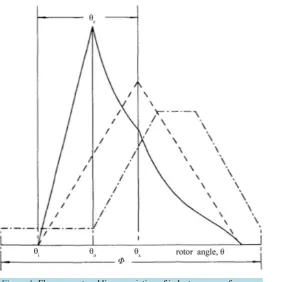
are dwell angleand speed respectively [22]. Due to high back EMF, the supply voltage is insufficient for chopping the current. Figure 1 shows a cycle of inductance profile, flux and current waveform of single phase of SRM [23].
If θo of winding is advanced by
θ
i on the onset of the rising inductance region, the inductance of thecir-cuit is minimum. This allows the current to build up rapidly. When the inductance profile starts increasing, the rising inductance and back EMF causes the current to fall until the switch is opened at some angle θx. When
the switch is OFF, due to opposing polarity being applied to the winding, the current flow starts decreasing more rapidly. To maintain peak flux at higher speeds, dwell angle must be increased proportionally with speed [23].
Let v0 be the phase voltage at the unaligned inductance region and the corresponding current be i0. Neg-lecting the resistive drop, Equation (2) at unaligned position can be rewritten as
0
0 u dd 0dd u
i L
v
ω
Lω
iθ
θ
= + (3)
where Lu, the unaligned inductance which is constant. Hence ddLθu =0.
0 0 dd
i
v
α
θ
∴ (4)
P. Saravanan et al.
Figure 1. Flux, current and linear variation of inductance waveforms.
( )
, dd
e l
T i T J B
t
ω
θ
− = +ω
(5)( )
,e
T θ i is the electromagnetic torque developed; J is the moment of inertia of both stator and rotor; Tl load
torque and B is the friction coefficient. As B is very low, B≈0 and
( )
, 2 d( )
,2 d
e i L i
T θ i θ
θ
=
(6)
From (5), (6)
( )
2 d ,
d 1
d 2 d l
L i i T t J θ ω θ = −
(7) For constant Tl and J, increasing current will increase accelerating torque and hence increases the speed.
2.2. Calculation of Turn-On and Turn-Off Angle
The turn-on and turn-off angles are the variables with respect to the speed of the motor and controller parame-ters. With increasing speed, fixed turn-on, turn-off angles may decrease electromagnetic torque and cause tail current, which leads to negative torque. To attain the maximum torque and efficiency, the switching parameters have to be adjusted proportional to speed. It is proposed that the calculation of turn ON angle of SRM as [8],
6 na m
on m
dc
L N I
V
θ =θ − ∗ (8)
In [4] the proposed turn-off angle theory with the assumption of non-saturable, piecewise linear gauge curve model, given as
(
)
2 24 1 m
off a m
ua dc m
I x N
R V
θ
θ θ
α
α
θ
∗ ∗ − ∗
= − − + +
∗ ∗
a ua
R R
α = (10)
ua u a
R =R R− (11)
where Ra and Ru are reciprocals of the aligned (La) and unaligned (Lna) inductances. m
N , speed (RPM);
dc
V , DC link voltage (V);
x is a constant (usually between 1 2 and
2 3); I is phase current (A);
m
θ is rotor position middle angle (˚).
3. Proposed Algorithm
The assumption of non-saturable inductance for the estimation of turn-off angle does not hold good for complete range of current [6]. The calculation of turn-on and turn-off angles at run time, increases the computations and thereby time consuming, made inappropriate for high speed of operations. A look-up table with pre-calculated turn-on and turn-off angles can be used, but the intermediate values have to be calculated using interpolation technique. Equations (8) and (9) are used to calculate turn-on, turn-off angles respectively for various current and speed at offline. It is inferred that the minimum required change in excitation parameters is 1%, hence the algorithm is structured to change the excitation parameters by 1% till the desired speed is reached.
The proposed algorithm is for 8/6 pole 4 phase SRM can be modified for any number of poles and phases. In this motor all the four phases has to be excited once in a stroke, with the stroke angle of 60 2
(
πNr)
. Accordingto the stator and rotor pole geometry, allowable dwell angle for the phase excitation is 15 to the maximum of 30 to avoid negative torque and torque ripples. From the two digital position sensors the position of the rotor poles are found for every 15˚ and the excitation patterns are derived using decoder.
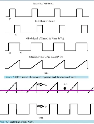
Consider the excitation of phase 3, as shown in Figure 2 the dwell angle starts at 30 and ends at 45 with respect to rotor position. It should be noted that the maximum allowable dwell angle is 30 and
ON
θ
starts from 15. At same instant the excitation (ON
θ
) of phase 2 also starts. The delay in phase excitation can be done with the inclusion of a delay routine program, after sensing the phase excitation signal. But it is difficult to ad-vance the phase excitation as it requires the assumption of turn-on time. Hence to adad-vance the dwell angle a new logic is presented as follows. The maximum dwell angle for any phase is calculated by logical OR of the excita-tion pattern of present phase and its previous phase. For instance, to estimate the maximum dwell angle for phase 3, the excitation signals of phase 3 and phase 2 from the decoder are logically ORed.The maximum dwell angle for phase 3 is from 15 to 45 of rotor position, during this interval required
ON
θ
and θOFF to reach the set speed is fixed. The ORed signal( )
VO which has been used to generate PWMfor the phase is integrated. The output of the integrator is in the form of saw tooth
( )
Vint . A variable 'K' is de-fined with initial value of the time taken by the rotor to move 30˚. It is calculated from the speed of the motor and equivalent to the width/height of the saw tooth of integrated wave.Figure 3 shows the PWM wave generated for the excitation of the phase, according to the conditions given in (8). where Vph is the supply to the phase windings. With increase in 'K', the pulse width gets reduced and hence
dwell angle.
int
int
1 if 2
0 if 2
ph K V V K V <
= >
(12)
With a change in motor speed, the new value of K is calculated, by comparing the set speed with actual speed. If the difference is positive, the K value is decreased by 1%, else K increased by 1%. For the 8/6 pole SRM, 1% cor-responds to 0.15˚. This procedure is repeated till the set speed is attained. It is expressed by Equation (9) as follows.
0.01 if
1 3
0.01 if for
4 4 if a s a s a s K K
K K K K K K
K ω ω ω ω ω ω + >
= − < < <
=
P. Saravanan et al.
Figure 2. ORed signal of consecutive phases and its integrated wave.
Figure 3.Generated PWM wave.
For higher value of K, phases will always be OFF, on the other hand for lesser value of K the phase will al-ways be ON. Hence, the value of K is restricted within the range of 1/4th to 3/4th of K for better performance.
Flow Chart
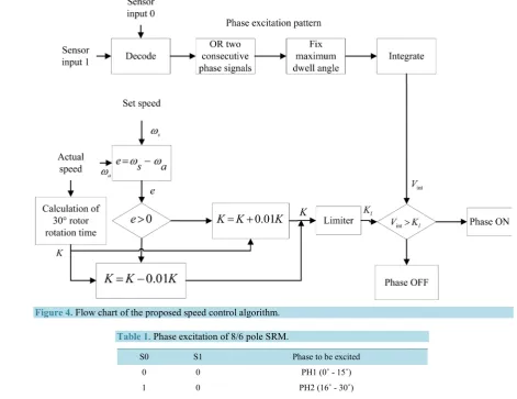
Figure 4 shows the flow chart for the proposed speed control algorithm. The outputs from the sensor signals are decoded to generate the phase excitation pattern. Two consecutive signals are ORed to fix the maximum dwell angle of the later phase. Then the ORed signal has been integrated (Vint). Value of K is initially calculated from actual speed ωa.
The difference (e) between the set speed and actual speed is evaluated. The value of K is modified, the phase excitation signal (Vph) is generated by Equations (12) and (13).
4. Simulation of Proposed Algorithm
Figure 4.Flow chart of the proposed speed control algorithm.
Table 1. Phase excitation of 8/6 pole SRM.
S0 S1 Phase to be excited
0 0 PH1 (0˚ - 15˚)
1 0 PH2 (16˚ - 30˚)
1 1 PH3 (31˚ - 45˚)
0 1 PH4 (46˚ - 60˚)
4.1. Sensor Module
The practical sensor signals S0, S1 has four different output states. It is modeled as per Expression (14)
15 30 45 60
1 2 0 1 0 1 0 1 0 1
0 16 31 46
d d d d
PP =
∫
S Sθ
+∫
S Sθ
+∫
S Sθ
+∫
S Sθ
(14)4.2. Decoder
With digital decoder, sensor outputs are mapped to the phase excitation as per Expression (15)
0 11
1 0
0 1
0 1
PH1 ,
PH2 ,
PH3 ,
PH4 .
S S S S S S S S
= = = =
(15)
4.3. Integrator and PWM Generator
In the next stage, two adjacent phases have been ORed and passed through integrator. Output is compared with 2
4.4. Generation of K and Limiter Module
From the actual speed the value of K is calculated and it is divided into 1/4K, 3/4K, to identify the safe region of operation. Finally the set speed is compared with actual speed and the error is generated. As per the algorithm the phase excitation signal is generated.
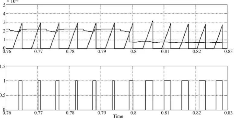
4.5. Simulation Results
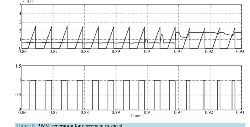
After building reasonable speed the switch has been closed to initiate the proposed speed control algorithm. With change in set speed, the motor respond to the variations dynamically and it is shown in Figure 6. The set speeds are 6000, 5000 and 5500. The generated PWM, and the comparison of K with integrated wave to increase and decrease the speed is shown in Figure 7 and Figure 8. It shows the varied dwell angle to decre-ment and incredecre-ment of speed.
The system responds to the variation of the set speed with respect to the higher and lower than actual speed.
5. Real Time Implementation
[image:9.595.189.439.306.474.2]Two primary platforms available for the implementation of the proposed speed control algorithm are FPGA and DSP. FPGAs are primary logic blocks connected by programmable wires to built unconventional processors.
Figure 6. Simulated results for different set speeds.
[image:9.595.121.511.504.707.2]P. Saravanan et al.
Figure 8. PWM generation for decrement in speed.
Combination of these logic blocks can be designed to function as per the proposed algorithm. FPGA has the highest level of re-configurability which makes it suitable for this kind of application, than DSP.
MATLAB-System Generator Toolbox provides a way of Direct Real Time Simulation and Implementation (DRTSI) using a FPGA that provides lower level of abstraction and modular design.
The above block diagram shows the complete model of the real time implementation of the algorithm (Figure 9). Speed is calculated by counting the number of pulses from the sensor outputs. Speed error generator block generates the difference (error) between set speed and actual speed. The change in K and PWM generation is done as discussed in section III. The value of K within the 1 3
4K K 4K
< <
limit is verified by saturation li-miter.
5.1. Experimental Results
8/6 motor is used for testing the proposed speed control algorithm and the specifications given in appendix. The system has been tested for wide range of speed and supplying a load of 200 Newton meter/second. The experi-mental setup of the developed speed control algorithm is shown in Figure 10, which includes the FPGA Nexys- 4 board, power converter and SRM with eddy current load. The signals from the sensors are analyzed with the DSO.
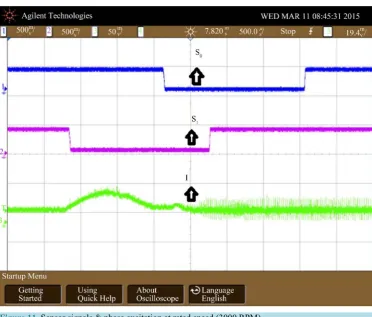
With the sensors signal (S0, S1) as ‘10’, phase 2 has been excited. The following scope waveform shows the same with the speed (rated) of 3000 RPM. When the speed is decreased to 1600 RPM, automatically the con-troller excites the phase at the appropriate time and it is shown in Figure 11 and Figure 12.
Increasing the speed (up to 6000 RPM), the controller automatically advances the phase excitation and it is shown in Figure 13.
5.2. Observation
Real time implementation of developed speed control algorithm has been realized with Nexys-4 FPGA Board. The digital control issues are addressed and the solutions are as follows:
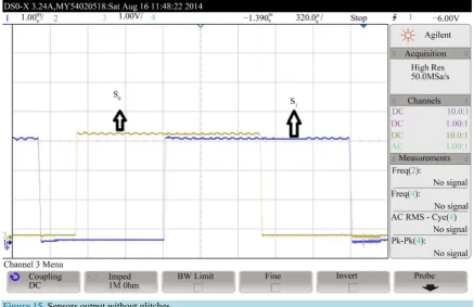
1) Signals from the position sensors are not of sufficient logic level. Hence to make it recognizable by Nex-ys-4 board, the signal is conditioned. For signal conditioning, Schmitt trigger with comparator circuit has been incorporated.
P. Saravanan et al.
Figure 10.Experimental set up of the speed control system.
Figure 11. Sensor signals & phase excitation at rated speed (3000 RPM).
[image:12.595.127.500.352.669.2]Figure 12.Sensor signals & Phase excitation at below rated speed (at 1600 RPM).
[image:13.595.129.498.404.705.2]P. Saravanan et al.
Figure 14. Sensor output with the presence of glitches.
Figure 15.Sensors output without glitches.
[image:14.595.94.532.385.668.2]6. Conclusion
In this paper, a speed control algorithm has been developed to change the switching parameters of SRM. A new technique has been presented for the phase advancement. The designed algorithm continuously monitors the speed and hence the change in load has also taken into consideration. The effectiveness of the proposed algo-rithm is validated with MATLAB-Simulink. At real time, the developed speed control algoalgo-rithm has been im-plemented with Xilinx Nexys-4 FPGA board. The geometric data of the motor have not been used in the de-signed algorithm; hence it can be implemented with the motor of different ratings. Further the algorithm can be improved by introducing the torque sharing functions to minimize torque ripples.
References
[1] Orthmann and Daimler, S. (1993) Turn-Off Angle Control of Switched Reluctance Motors for Optimum Torque Out-put. The European Power Electronics Association, 6, 20-25.
[2] Stiebler, M. and Jie, G. (1992) A Low Voltage Switched Reluctance Motor with Experimentally Optimized Control.
Proceedings of ICEM '92, 2, 532-536.
[3] Takahashi, T., Chiba, A., Ikeda, K. and Fukao, T. (1993) A Comparison of Output Power Control Methods of Switched Reluctance Motors. IEEE Xplore Conference: Power Conversion Conference, Yokohama, 19-21 April 1993, 390-395. [4] Torrey, D.A. and Lang, J.H. (1990) Modelling Nonlinear Variable Reluctance Motor Drive. Proceedings of IEE, 137,
314-326. http://dx.doi.org/10.1049/ip-b.1990.0038
[5] Gribble, J.J., Kjaler, P.C., Cossar, C. and Miller, T.J.E. (1996) Optimal Commutation Angles for Current Controlled Switched Reluctance Motors. IEE Conference on Power Electronics and Variable Speed Drives, 23-25 September, 87-92.
[6] Gribble, J.J., Kjaler, P.C., Cossar, C. and Miller, T.J.E. (1999) Optimal Commutation in Average Torque Control of Switched Reluctance Motors. IEE Proceedings Electrical Power Applications, 146, 2-10.
http://dx.doi.org/10.1049/ip-epa:19990204
[7] Kjaer, P.C., Nielsen, P., Andersen, L. and Blaabjerg, F. (1995) A New Energy Optimizing Control Strategy for Switched Reluctance Motors. IEEE Transactions on Industry Applications, 31, 1088-1095.
http://dx.doi.org/10.1109/28.464523
[8] Bose, B.K., Miller, T.J.E., Szczesny, P.M. and Bicknell, W.H. (1986) Microcomputer Control of Switched Reluctance Motor. IEEE Transactions on Industry Applications, IA-22, 708-715. http://dx.doi.org/10.1109/TIA.1986.4504782 [9] Sozer, Y., Torrey, D.A. and Mese, E. (2003) Automatic Control of Excitation Parameters for Switched-Reluctance
Motor Drives. IEEE Transactions on Power Electronics, 18, 594-603. http://dx.doi.org/10.1109/TPEL.2003.809352 [10] Akhter, H.E., Sham, V.K., ChantIra, A. and AI-Enddad, K. (2002) Starting Performance of Switched Reluctance Motor
with Fixed Turn-Off Angle Control Scheme. IECON 02, Industrial Electronics Society, IEEE 2002 28th Annual Con-ference, 2, 1020-1025.
[11] Mademlis, C. and Kioskeridis, I. (2003) Performance Optimization in Switched Reluctance Motor Drives with Online Commutation Angle Control. IEEE Transactions on Energy Conversion, 18, 448-457.
http://dx.doi.org/10.1109/TEC.2003.815854
[12] Se, J.-Y., et al. (2001) Speed Control Method for Switched Reluctance Motor Drive Using Self-Tuning of Switching Angle. ISIE, 2, 811-815.
[13] Chappell and Blake (1984) Microprocessor Control of a Variable Reluctance Motor. IEE PROCEEDINGS, 131, 51-60. [14] Fatemi, S.A., Moradi, C.H. and Afjei, E. (2009) Self-Tuning Approach to Optimization of Excitation Angles for
Switched-Reluctance Motor Drives. European Conference on Circuit Theory and Design, ECCTD 2009, Antalya, 23-27 August 2009, 851-856. http://dx.doi.org/10.1109/ecctd.2009.5275117
[15] Blanque, B., Perat, J.L., Andrada, P. and Torrent, M. (2005) Improving Efficiency in Switched Reluctance Motor Drives with Online Control of Turn-On and Turn-Off Angles. EPE, 2005 DRESTON.
[16] Sozer, Y. and Torrey, D.A. (2007) Optimal Turn-Off Angle Control in the Face of Automatic Turn-On Angle Control for Switched-Reluctance Motors. IET Electrical Power Applications, 1, 395-401.
http://dx.doi.org/10.1049/iet-epa:20060412
[17] Ma, Q.Q., Bi, D.Q. and Ge, B.M. (2012) Digital Control Issue of High Speed Switched Reluctance Motor. IEEE In-ternational Symposium on Industrial Electronics (ISIE), 28-31 May 2012, Hangzhou, 641-646.
P. Saravanan et al.
[19] Ferreira, J., et al. (1995) Detailed Design of a 30-kW Switched Reluctance Starter/Generator System for a Gas Turbine Engine Application. IEEE Transactions on Industry Applications, 31, 553-56. http://dx.doi.org/10.1109/28.382116 [20] Zhou, Q. and Liu, C. (2009) The Digital Controller of High Speed Switched Reluctance Motor Based on ASIC.
Trans-actions of China Electro technical Society, 3, 5-60.
[21] Krishnan, R. (2001) Switched Reluctance Motor Drives: Modelling, Simulation, Analysis, Design and Applications. CRC Press, LLC, USA.
[22] Miller, T.J.E. (2001) Electronic Control of Switched Reluctance Machines. Newnes, Chapter 5 & 6, Oxford.