Eff e c t of c o r r e l a ti o n a n d
d i el e c t ri c c o nfi n e m e n t o n
1 S 1 / 2( e) n S 3 / 2( h) Ex ci t o n s i n
C dT e/C d S e a n d C d S e / C dT e Ty p
e-II q u a n t u m d o t s
Ty r r ell, EJ a n d To mi c, S
h t t p :// dx. d oi.o r g / 1 0 . 1 0 2 1 / a c s.j p c c . 5 b 0 2 7 8 9
T i t l e
Eff e c t of c o r r el a ti o n a n d d i el e c t ri c c o nfi n e m e n t o n
1 S 1 / 2( e) n S 3 / 2( h) Ex ci t o n s i n C dT e/C d S e a n d C d S e / C dT e
Ty p e-II q u a n t u m d o t s
A u t h o r s
Ty r r ell, EJ a n d To mi c, S
Typ e
Ar ticl e
U RL
T hi s v e r si o n is a v ail a bl e a t :
h t t p :// u sir. s alfo r d . a c . u k /i d/ e p ri n t/ 3 7 3 5 7 /
P u b l i s h e d D a t e
2 0 1 5
U S IR is a d i gi t al c oll e c ti o n of t h e r e s e a r c h o u t p u t of t h e U n iv e r si ty of S alfo r d .
W h e r e c o p y ri g h t p e r m i t s , f ull t e x t m a t e r i al h el d i n t h e r e p o si t o r y is m a d e
f r e ely a v ail a bl e o nli n e a n d c a n b e r e a d , d o w nl o a d e d a n d c o pi e d fo r n o
n-c o m m e r n-ci al p r iv a t e s t u d y o r r e s e a r n-c h p u r p o s e s . Pl e a s e n-c h e n-c k t h e m a n u s n-c ri p t
fo r a n y f u r t h e r c o p y ri g h t r e s t r i c ti o n s .
The E
↵
ect of Correlation and Dielectric Confinement on
1
S
1/2nS
3/2Excitons in
CdTe/CdSe and CdSe/CdTe Type-II Quantum Dots
Edward J. Tyrrell and Stanko Tomi´c⇤
Joule Physics Laboratory, University of Salford, Manchester M5 4WT, United Kingdom (Dated: May 5, 2015)
Abstract
We calculate correlated exciton states in type-II core/shell quantum dots (QDs) using a configu-ration interaction method combined with thek·ptheory. We map the 1S(e)1/21S3/2(h) and 1S1/2(e)2S(h)3/2
exciton correlation energy relative to the strong confinement approximation as a function of core radius, shell thickness and dielectric confinement. The type-II confinement potentials enhance the e↵ect of dielectric confinement which can significantly a↵ect the wave functions and exciton energies in such heterostructures. Dielectric confinement mainly increases the correlation energy for QDs in which the corresponding single-particle hole states are delocalized. We also find that correlation leads to large changes in the optical dipole matrix element, particularly for the lowest CdSe/CdTe QD exciton, in the presence of dielectric confinement. We conclude that dielectric confinement af-fected the exciton properties in CdSe/CdTe QDs more than in CdTe/CdSe QDs due to the band alignment which encourages holes to localize in the shell.
Keywords: correlation, colloidal quantum dots, optical properties
I. INTRODUCTION
Semiconductor nanocrystals or quantum dots (QDs) are the subject of intensive research, due to a number of novel properties which make them attractive for both fundamental studies and technological applications.1–6
QDs are of particular interest for solar cell applications due to their ability to increase efficiency via the gen-eration of multiexcitons from a single photon.7–9 QDs
can be synthesized with a high degree of control using colloidal chemistry.10,11 Much research e↵ort has been
directed towards studying QDs grown from more than one semiconductor, e.g. core/shell heterostructures.12–14
Such core/shell nanostructures provide a means to con-trol the optical properties by tuning the electron-hole wave function overlap which is a↵ected by the alignment of the conduction band (CB) and valence band (VB) edges, as well as the QD shape and size. In contrast to type-I band alignments, type-II alignments have stag-gered CB and VB edges so the lowest energy states for electrons and holes lie in di↵erent spatial regions, lead-ing to charge separation between the carriers. Type-II core/shell QDs can be classified according to whether the band alignments tend to localize the hole in the core and electron in the shell (h/eQDs, such as CdTe/CdSe QDs) or the electron in the core and the hole in the shell (e/h
QDs, such as CdSe/CdTe QDs).15 Such staggered band
alignments have several useful physical consequences, in-cluding longer radiative recombination times for more ef-ficient charge extraction in photovoltaic applications,16,17
optical gaps that can be made smaller than the bulk val-ues of the constituent materials12,18,19and control of the
electron-hole wave function overlap which determines the exchange interaction energy.20Charge separation in
type-II QDs can also be used to increase the repulsion between like-sign charges in biexciton states,21,22 leading to the
possibility of lasing in the single exciton regime.6,23,24
To determine the energetics of many-body states in QDs, both the confinement potential and many-body in-teractions between the carriers need to be taken into account. Many-body interactions can be classified as Coulomb (charge) and Fermi (spin) correlation. Coulomb correlation arises from the electrostatic interaction of charge carriers in the many-body complex, whilst spin correlation occurs due to the fermionic character of the charge carriers (i.e. the Pauli exclusion principle).25
Cor-related many-body states may be calculated with the configuration interaction (CI) method which can be used in the framework of continuum or atomistic descriptions of single-particle states.26–31
Colloidal QDs are usually embedded or dispersed in media32of lower dielectric constant than the
semiconduc-tor itself - this dielectric confinement leads to a modifica-tion of the Coulomb interacmodifica-tion which can be described using classical image charge theory. Whilst atomistic calculations33showed that dielectric confinement
signif-icantly a↵ects the charging energies of QDs, in single-material spherical QDs the similar electron and hole charge distributions lead to a weakened dielectric con-finement e↵ect34on exciton states which mainly increases
the binding energy.26,35It is therefore natural to wonder
if the optical properties of spherical type-II core/shell QDs can be significantly a↵ected by the dielectric envi-ronment.
compu-tationally expensive as the number of states increases. Luckily however the interpretation of physical experi-ments often requires detailed knowledge of just a few ex-citons of particular symmetry. To overcome the unneces-sary computational burden, when analysing 1S(1e/)2nS3(h/2)
excitons in core/shell QD structures, we develop a decou-pled CI calculation method which only mixes the most important,ms(1e/)2ns(3h/)2, single-particle states into the ex-citon wave function but accurately reproduces the full CI results with greatly reduced computational cost. This allows us to evaluate the e↵ect of correlation on exciton energies and dipole matrix elements for many di↵erent core/shell QD geometries, and identify those designs for which correlation e↵ects are greatest.
In this paper we examine the 1S1(e/)21S3(h/)2 and
1S1(e/)22S(3h/2)excitons in CdTe/CdSe and CdSe/CdTe QDs using a CI approach to describe the e↵ect of correlation between the electron and hole states. The single-particle states were described using the (2,6)-bandk·ptheory36
for spherical core/shell QD heterostructures, taking into account correct operator ordering at the heterointerfaces and the complex VB structure.
II. THEORETICAL MODEL
A. Single-particle states
In order to find a set of single-particle (SP) states we use the (2,6)-bandk·pHamiltonian.36To illustrate the
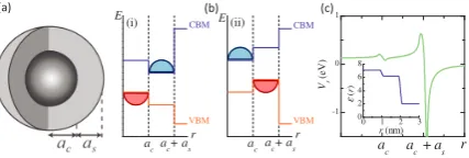
problem and introduce basic parameters, in Fig. 1 we show: (a) a schematic of a spherical QD characterized by core radius ac and shell thickness as, (b) the stag-gered alignments of the CB minimum (CBM) and VB maximum (VBM) in type-II h/e CdTe/CdSe and e/h
CdSe/CdTe QDs; and (c) a characteristic profile of the self-polarization potential due to the contrast between dielectric constants of QD and surrounding medium (col-loid). Details of material parameters used can be found in the Appendix.
The electron (hole) SP wave function j,m,p,ne(h) satisfies the Schr¨odinger equation
ˆ
He(h) j,m,p,ne(h) =E e(h)
j,p,n e(h)
j,m,p,n (1)
whereEj,p,ne(h) is the electron (hole) eigenenergy and ˆHe(h)
is the k· p Hamiltonian for electrons (holes). The SP quantum states are denoted using the notation, nlj(µ), where n is the fundamental quantum number, l =
s, p, d, ...represents the lowest value of the orbital angular momentum in the wave function, andµ2{e, h}denotes an electron or hole.37 Due to the macroscopic spherical
symmetry of the QD shape and the fact that the mate-rial parameters depend on the radial coordinater only, the states calculated according the k·p theory can be characterized by the total angular momentumj and its
-1 0 1
0 1 2 3 0 2 4 6 8
r ac + a
s
a
c Vs
(e
V
)
ε
(
r
)
r (nm) (ii)
ac+ as
a
c+ as ac
r VBM VBM
CBM CBM
r a
c
E
(i) E
(a) (b) (c)
FIG. 1: (a) A cutaway view of a spherical core/shell QD; (b) the CBM and VBM corresponding to type-II alignment, in (i) anh/eCdTe/CdSe QD and (ii) ane/hCdSe/CdTe QD; (c) a typical self-polarization potential for a colloidal CdTe/CdSe QD, with dielectric profile (inset).
z-componentm⌘jz.36Furthermore the parity operator ˆ
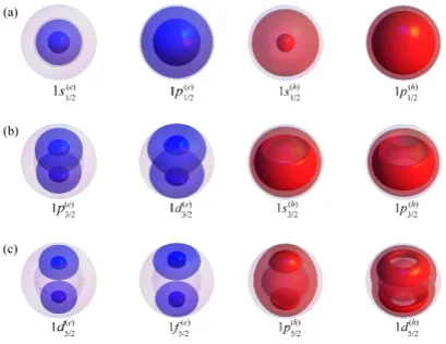
P commutes with the Hamiltonian ˆH of any system pos-sessing a spherically symmetric confining potentialV, so that ˆH and ˆP share the same set of eigenfunctions. As a result SP eigenstates in spherical QDs are also charac-terized by the eigenvaluepof the parity operator;ptakes the values 1 and 1 for even and odd states respectively. In spherical QDs possessing spherically symmetric con-finement potentials the parity is conserved. Furthermore the radial part of the wave function can be classified ac-cording to whether it has odd or even parity. In Figs. 2 and 3 we show charge densities ofn= 1,m= 1
2 electron
and hole SP states with (a) j = 12, (b) j = 32 and (c)
j= 5
2 in CdTe/CdSe and CdSe/CdTe QDs respectively.
SP states withj = 1
2 have spherically symmetric charge
densities and all SP states withm=±1
2 are symmetric
about thez-axis.
B. Exciton States
Our SP ket notation |jmpni is defined in terms of total angular momentum j and parity p, such that
hrµ|jmpni= j,m,p,nµ (rµ). To construct excitonic states we couple SP states in terms of angular momentum rather than parity, so we define the new ket notation
|nljmiin terms of both total angular momentm j and lowest value of orbital angular momentum l. In such notation l = j p/2 for electrons and l = min(j +
[image:3.595.347.561.113.185.2]FIG. 2: Probability density isosurfaces of SP states in an
ac = 2 nm, as = 1 nm CdTe/CdSe QD; transparent (opaque) surfaces represent 25% (75%) of the maximum value of| e(h)j,m,p,n|2.
FIG. 3: Probability density isosurfaces of SP states in an
ac = 2 nm, as = 1 nm CdSe/CdTe QD; transparent (opaque) surfaces represent 25% (75%) of the maximum value of| e(h)j,m,p,n|2.
Exciton Hamiltonian: In the presence of a spatially varying dielectric constant the exciton Hamiltonian is26
ˆ
HX = ˆHe+ ˆHh+Vc(re,rh) +Vs(re) +Vs(rh) (2)
where Vc is the interparticle Coulomb potential and Vs is the self-polarization potential due to the interaction of a carrier with its own polarization charge. We note that Vc = Vd +Vp where Vd is the direct interparti-cle Coulomb potential and Vp is the interface polariza-tion potential.15,38 Excitonic states are solutions of the
Schr¨odinger equation
ˆ
HX| L,LX zi=EX| L,LX zi, (3)
where L is the total exciton angular momentum, Lz is itsz-component andEX is the exciton eigenenergy. The
exciton wave function can be expanded in terms of un-correlated electron-hole pair (EHP) states as27
| L,Lz
X i=
X
={ne,le,je,nh,lh,jh}
c |nelejenhlhjh;LLzi (4)
where
|nelejenhlhjh;LLzi=
X
me,mh
CL,Lz
je,me;jh,mh|nelejemei|nhlhjhmhi (5)
and theCL,Lz
je,me;jh,mh are Clebsch-Gordan coefficients. In
Eq. (4) c is the expansion coefficient (character) of a particularms(1e/)2ns3(h/)2 (m, n2N) EHP state labeled by . SinceL and Lz are conserved for correlated exciton states the Hamiltonian ˆHX can diagonalized separately in di↵erent (L,Lz)-subspaces.27
C. Correlation energy and momentum
Assuming the form of excitonic wave function in Eq. (4), the correlation energy of the 1S1(e/)2nS3(/h2)(n2N) excitons can be defined as:
Ecorr=EX,CI EX, (6)
whereEX is the exciton energy calculated according to first order perturbation theory (FOPT) inside the strong confinement approximation (SCA) for the exciton wave function.35,38–40
The probability of excitation from the ground to the exciton state| L,Lz
X iis proportional to the square of the optical dipole matrix element:41
PX2 =|h0|ˆe·pˆh| L,LX zi|2 (7)
where ˆeis the polarization vector of incident light and ˆph is the hole momentum operator. Substituting for| L,Lz
X i from Eq. (4) gives
PX,2CI=|Xc h0|ˆe·pˆh|nelejenhlhjh;LLzi|2 (8)
where each term in Eq. (8) must obey the selection rules for electric dipole transitions. Optical dipole matrix ele-ments of the uncorrelated states are calculated as:
P2=|h e
j,m,p,n|ˆe·pˆh| hj0,m0,p0,n0i|2. (9)
To assess the e↵ect of correlation on the excitonic optical dipole matrix elements we define:51
PX2 =PX,2CI 1
4P
2. (10)
Thecharge densityof the electron (hole) in the corre-lated exciton is
⇢µX(r) =h L,Lz
[image:4.595.79.284.299.457.2]However, sinces(1e/)2states are spherically symmetric and
s(3h/)2 states often approximately spheroidal (see Figs. 2 and 3) it is more informative to examine the radial prob-ability density (RPD). The electron RPD is
RPDe(r) = 1 4
X
, 0
c⇤0c n0
h,nh[R
e;1
2,1,n0
1
2,0
(r)]⇤Re;12,1,n 1
2,0
(r)r2.
(12) Similarly we define a hole RPD as
RPDh(r) = 1 4
X
0,
c⇤0c n0e,ne{[R
h;3
2,1,n0
3
2,2 (r)]
⇤Rh;3
2,1,n
3
2,2 (r)
+ [Rh;32,1,n0 3
2,0
(r)]⇤Rh;32,1,n 3
2,0
(r)
+ [Rh;32,1,n0 1
2,2
(r)]⇤Rh;32,1,n 1
2,2
(r)}r2 (13)
where RµJ,l;j,p,n is the radial part of the electron (hole) wave function26,36 andJ is the total Bloch function
an-gular momentum. The corresponding SP charge densities are denoted as⇢µSP. We also define the probability pc(s)
of the SP hole being in the core (shell) region as
pc=
Z ac
0
⇢hSP(r)dr, ps=
Z ac+as
ac
⇢hSP(r)dr. (14)
D. The e↵ect of dielectric confinement
For colloidal QDs the dielectric constant" of the QD material is typically much larger than that of the sur-rounding medium. Such dielectric contrast means that any free charge in the QD induces polarization charge in the QD and its surroundings. The overall e↵ect of the induced charge on a source charge is described by the self-polarization potentialVs(r) which cannot be ignored, Fig. 1(c). In colloidal core/shell QDs the self-polarization potential is characterised by a small peak and well near the core/shell interface due to the small dielectric mis-match between the core and shell materials. However a much larger peak just inside r = ac+as and a deep well slightly outside the QD are due to the far greater dielectric mismatch of the shell and matrix material.
In order to assess the e↵ect of dielectric confinement on the excitonic structure of CdTe/CdSe and CdSe/CdTe core/shell QDs we performed CI calculations for two dif-ferent situations: assuming a uniform dielectric constant
"= const.= 6.65 (i.e. the mean of the CdTe and CdSe constants so that dielectric confinement by the surround-ing medium and dielectric mismatch of the core and shell were neglected) and using a realistic profile"="(r) with the individual dielectric constants for the core, shell and external medium. In the former case the Coulomb inter-action Vc in Eq. (2) reduces to the direct interparticle term Vd only, allowing us to separate the e↵ects of the interparticle Coulomb attraction and dielectric confine-ment.
III. RESULTS AND DISCUSSION
A. Convergence considerations
For a general exciton state | L,Lz
[image:5.595.63.299.112.253.2]X i there are many combinations of SP states that should be summed over in Eq. (5); this number can be reduced by considering the states that can be coupled for specific cases. Angular momentum coupling conditions mean that for optically active L = 1 states |je jh| 1; assuming Lz = 1 meansme+mh = 1. If incident light is polarized par-allel to the z-axis only EHPs with me = mh = 12 are excited. These assumptions still leave a large number of possible basis states to calculate matrix elements for, since|nelejenhlhjh;LLzi in Eq. (5) must be expanded over di↵erent ordinal quantum numbersnµ and angular momenta lµ. To investigate the relative importance of di↵erent SP states we calculateEX as a function of the number of states in the EHP basis. We include hole states up toj= 152 and all confined electron states in afull con-figuration interaction(FCI) scheme. Figure 4 shows the
FIG. 4: Convergence ofEFCI
X as a function of (a)nFCIe and (b)nFCI
h forac= 2 nm,as= 0.5 nm CdTe/CdSe QD. convergence of the exciton energyEFCI
X calculated in the FCI scheme for the 1S(1e/)21S3(h/)2 exciton against (a) the number of electron states nFCI
e and (b) the number of hole statesnFCI
h in the basis. We see thatEXFCIchanges in a stepwise fashion with the addition of extra states to the basis - falling from its FOPT value of 1866.38 meV to 1856.13 meV whennFCI
e =nFCIh = 30. Fornh= 20 the energyEFCI
X changes by 5-6 meV atnFCIe = 7, while when ne = 20 is fixed the energyEXFCIchanges by⇠2 meV at nFCI
h = 5 and by an additional ⇠1 meV at nFCIh = 15. We have identified that the seventh electron state in the FCI basis is the 2s(1e/)2state, whilst the fifth and fifteenth
[image:5.595.321.551.317.485.2](n 2 N) excitons are mainly composed of ms1(e/)2ns(3h/)2
(m, n2 N) EHPs. Therefore we developed a decoupled configuration interaction(DCI) scheme in which the EHP basis consists solely ofms(1e/)2ns3(h/)2(m, n2N) pair states. For example the calculation represented in Fig. 4 is fully reproduced by the DCI scheme which includes only the first twos(1e/)2 states and first threes(3h/)2 states. The FCI calculation gave EFCI
X = 1856.13 meV and 2055.88 meV for the 1S(1e/)21S3(h/)2 and 1S(1e/)22S3(h/)2 excitons respectively while the DCI calculation gaveEDCI
X = 1857.00 meV and 2057.29 meV for the same states (equivalent to a relative error of 1.4⇥10 2% and 5.1⇥10 2% respectively).52
Due to the greatly reduced computational load all rele-vant results are easily converged within this framework.
B. Comparison with experiment
The 1S1(e/)2nS3(h/)2 (n = 1,2) states are the two low-est energy excitons observed in the absorption spectra of colloidal CdTe/CdSe NCs,21,39,42 making them the
most important for understanding the near band-edge absorption characteristics of such nanoparticles. Fig-ure 5 shows the 1S1(e/)21S3(h/)2 and 1S(1e/)22S3(h/)2 exciton en-ergies (solid lines) calculated in the DCI scheme as a function of shell thickness for CdTe/CdSe QDs with (a)
ac = 1.7 nm, (b) ac = 1.72 nm, (c) ac = 1.75 nm and (d) ac = 1.95 nm. Dashed lines show upper and lower limits on the exciton energies resulting from an uncer-tainty of 1 monolayer (ML) in the displayed core radii (⇠±0.3 nm). Filled circles show exciton energies taken from the first and second absorption peak positions in absorption spectra measured by (a) Gong et al.,42 (b)
Maet al.,43(c) Caiet al.44and (d) Oronet al.21. We see
good quantitative agreement between the calculated ex-citon energies and the experimental data, with the data lying in the channels defined by an uncertainty of±1 ML width in the core size. It should be noted that the re-sults of Oron et al.21 were obtained on zinc-blende NC
structures, in addition to those of Caiet al.44The papers
by Gonget al.42and Ma et al.43 do not explicitly state
the crystal structures of the core/shell nanoparticles, al-though Maet al.43 note that their core/shell NCs gave
very similar absorption and photoluminescence spectra to those of Cai and coworkers.44Our calculations
accu-rately reproduce the 0.25 eV energy separation between the 1S1(e/)21S3(h/2)and 1S1(e/)22S3(h/2)excitons that is nearly in-dependent of shell thickness.42This constant energy
sep-aration is characteristic of changing electron confinement but approximately constant hole confinement in theh/e
heterostructure. We also find good agreement between the oscillator strength obtained by Gong et al.42 from
the absorption spectra and our calculations. Calculating the oscillator strengthfnof the 1S1(e/)2nS(3h/2)(n= 1,2) ex-citons asfn= 2PX,2DCI/m0EX,DCIwe find thatf1+f2⇠
FIG. 5: Energies of the 1S1/2(e)nS3/2(h) (n= 1,2) excitons cal-culated in the DCI scheme (lines) for CdTe/CdSe QDs with (a)ac = 1.7 nm, (b) ac = 1.72 nm, (c)ac = 1.75 nm and (d)ac = 1.95 nm; experimental data taken from Refs. 42, 43,44 and 21 are shown as filled symbols. Error bars represent an uncertainty of 1 ML (⇡ ±0.3 nm) in the shell thickness. Dashed lines show upper and lower limits on the exciton en-ergies resulting from an uncertainty of 1 ML in the nominal core radii.
constant (inset Fig. 5), confirming the validity of relevant excitonic wave functions too.
C. Correlation energies
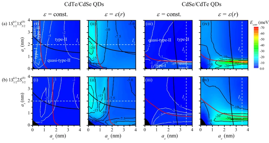
Figure 6 showsEcorrfor the 1S1(e/)21S3(h/)2and 1S(1e/)22S3(h/)2
excitons in CdTe/CdSe and CdSe/CdTe QDs. Black and red lines represent the localization boundaries (LBs) for the electron and hole respectively.15 In the CdTe/CdSe
FIG. 6: The correlation energy, Ecorr, of (a) the 1S1/2(e)1S (h)
3/2 and (b) the 1S (e) 1/22S
(h)
3/2 exciton in CdTe/CdSe and CdSe/CdTe QDs. (i) and (iii) corresponds to"= const., whilst (ii) and (iv) corresponds to"="(r), respectively. Electron (hole) LBs are shown as black (red) lines.
this corresponds to a delocalized hole and shell-localized electron or a core-localized hole and delocalized electron in thee/hQD.
Areas of significant magnitude correlation energy in Fig. 6 always roughly coincide with those associated with large optical dipole matrix elements for the correspond-ing uncorrelated EHPs.39 In those regions the
electron-hole correlation is enhanced as the SP wave function overlap is high and the interparticle Coulomb matrix ele-ments are increased in magnitude. In the type-II regimes
|Ecorr|is mainly small since the spatial separation of the
electron and hole (induced by the type-II band align-ment) overrides Coulomb attraction. In those regions the exciton wave function is closer to being described by the SCA. Although areas of high |Ecorr| partly overlap
with the type-II regions the trend is for Ecorr ! 0 in
the type-II localization limit. The highest |Ecorr|values
in Fig. 6 are a consequence of dielectric confinement af-fecting the correlated hole density [see (a,iv) and (b,iv)], reflected by the fact that they mainly occur in regions where the corresponding SP hole is delocalized. For ex-ample, in CdTe/CdSe QDs dielectric mismatch increases
|Ecorr|for the 1S1(e/)2nS3(h/2)(n= 1,2) excitons in structures
in which the corresponding ns(3h/)2 states are delocalized (or approximately so) over the whole QD. Once strongly core-localized (right of the LB) such SP hole states have little or no overlap with the self-polarization potential near the QD/medium interface. Similarly dielectric mis-match mostly a↵ectsEcorr for the 1S(1e/)2nS3(h/2) (n= 1,2)
excitons in CdSe/CdTe QDs which lie below or near the hole LB (corresponding to delocalized SP holes). Figure 6(a, iv) and (b, iv) also show that Ecorr has a distinct
minimum as a function ofas. This minimum is due to the fact that an increase in as causes the hole density to shift into the shell where it starts to be a↵ected by the self-polarization potential at the QD/medium inter-face. However, asas increases further the hole localizes completely in the shell so that spatial confinement by the VBM overrides the repulsive e↵ect of the self-polarization potential causingEcorr!0; see Sec. III D 2 for detailed
explanations.
For the 1S1(e/)21S(3h/2) exciton the area of non-zero Ecorr
in the lower right quasi-type-II regime of the CdTe/CdSe QD, Fig. 6(a,ii)), is equivalent to the area in the up-per left quasi-type-II regime of the CdSe/CdTe QD, Fig. 6(a,iv). Similarly the region of large |Ecorr| for the
1S1(e/)22S3(h/)2 exciton at ac & 2 nm, as . 0.5 nm in Fig. 6(b,ii) is analogous to the area atac .2.5 nm, as&1.5 nm in Fig. 6(b,iv).
the resulting correlated hole density has more ‘degrees of freedom’ to adjust to the e↵ects of dielectric confinement.
D. Correlated exciton states
1. CdTe/CdSe QD: e↵ect of electron shell localization
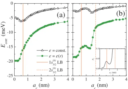
In Figure 7 we present Ecorr for the 1S1(e/)21S(3h/2) and
1S1(e/)22S(3h/2)excitons as a function of core radius for fixed shellas= 2 nm CdTe/CdSe QDs (linel1in Fig. 6).
We see that in the presence of dielectric confinement
|Ecorr| . 20 meV for both excitons and that Ecorr
ex-hibits at least one minimum as a function of ac in the
" = const. and " = "(r) case. |Ecorr| is up to four
times greater in the presence of dielectric confinement (" = "(r)) compared to the " = const. case. This re-sult highlights the importance of a proper treatment of the dielectric environment in such nano-structures. The minimum inEcorr for the 1S(1e/)21S3(h/)2exciton, Fig. 7(a),
is a consequence of two competing e↵ects: proximity of the self-polarization potential peak which tends to re-duce the electron-hole separation and the e↵ect of the type-II confinement profile which tends to separate the carriers asac increases. However, for the 1S1(e/)22S
(h) 3/2
ex-citon Ecorr is not a monotonic function of ac either for
" = "(r) or " = const. Insight into the QD size depen-dence ofEcorrcan be gained by considering the amount of
probability density in the core and shell associated with the dominant SP hole state that the correlated exciton originates from. The inset in Fig. 7(b) shows the amount of 2s(3h/)2hole probability density in the core as a function ofac, demonstrating a similar qualitativeac dependence to Ecorr in the dielectric mismatch case. We expect an
increase inpcto cause a decrease in|Ecorr|since a greater
amount of hole density in the core leads to less overlap with electron density in the shell and less correlation.
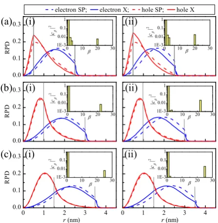
1S1(e/)21S3(h/)2 exciton: Figure 8 shows the RPDs of the
correlated 1S1(e/)21S(3h/2) exciton (solid lines) compared to
the 1s(1e/)21s(3h/)2 EHP (dotted lines) as a function of ac when (i)"= const.and (ii)"="(r). The shifts due to the direct interparticle Coulomb interaction are relatively small when " = const. and both carriers move slightly towards the core. By increasingacto⇠1 nm and beyond, the hole mainly localizes in the core so that⇢h
X '⇢hSPand
the SCA regime is reached, where the spatial confinement outweighs e↵ect of correlations.
When "= "(r) the increased values of |Ecorr| are
as-sociated with a shift of RPD away from the QD surface due to repulsion by the large peak in the self-polarization potential nearr=ac+as. The correlated electron is af-fected more since the electron SP states tend to localize in the shell. The exciton wave function gains 2s(1e/)21s(3h/)2
character corresponding to the = 20 and = 25 EHP for theac= 0.5 and 1.5 nm QDs respectively. The hole
0 1 2 3 4
-25 -20 -15 -10 -5 0
0 1 2 3 4
(b)
E co
rr
(
m
eV
)
a
c (nm)
(a)
0 1 2 3
0.00 0.05 0.10
pc
a
c(nm) ε =const.
ε =ε(r)
1s(h)
3/2 LB
2s(h)
3/2 LB
a
[image:8.595.321.545.78.235.2]c (nm)
FIG. 7: Ecorr of (a) 1S1/2(e)1S3/2(h) and (b) 1S1/2(e)2S3/2(h) excitons inas = 2 nm CdTe/CdSe QDs along the linel1 in Fig. 6. Cases of"= const.and"="(r) are represented by open and solid symbols respectively. The inset showspc for the 2s(h)3/2 SP state.
is only slightly a↵ected by the self-polarization potential near the QD surface when there is a significant amount of hole charge density in the shell, as in the case of small
ac.
1S1(e/)22S(3h/2) exciton: In the absence of dielectric con-finement |Ecorr| is always small (.3 meV) because the
exciton state is very close to the 1s(1e/)22s(3h/)2( = 2) EHP state and |c2|2 ' 1. When " = "(r) the trend is very
similar to the 1S1(e/)21S(3h/2) exciton, except di↵erent EHP characters are involved. For example, in theac = 1 nm QD the correlated exciton wave function is mainly com-posed of the = 3,4 and 23 (1s1(e/)23s(3h/2), 1s(1e/)24s(3h/)2,
2s(1e/)22s3(h/)2) EHPs; while in the ac = 1.5 nm QD, the
= 3 and 26 (1s(1e/)23s(3h/)2, 2s(1e/)22s(3h/)2) EHPs are domi-nant. Again, when the hole localizes in the core only the electron is significantly a↵ected by dielectric mismatch.
2. CdSe/CdTe QD: e↵ect of hole shell localization
In Fig. 9 we present Ecorr for the 1S1(e/)21S3(h/2) and
1S1(e/)22S3(h/)2 excitons as a function of shell thickness for an ac = 3.5 nm fixed core in CdSe/CdTe QDs (line l2
in Fig. 6). We observe the largest size correlation en-ergy of the considered excitons for the 1S(1e/)21S3(h/)2 state in CdSe/CdTe QDs when"= "(r), withEcorr reaching
ef-FIG. 8: Solid (dashed) lines represent RPDs of the 1S1/2(e)1S(h)3/2
exciton (1s(e)1/21s(h)3/2EHP) of CdTe/CdSe QDs withas= 2 nm and (a)ac= 0.5, and (b)ac= 1.5 nm for (i)"= const.and
(ii) " = "(r). Vertical lines denote the boundaries between
the core, shell and external medium. Insets are barcharts of
|c |2characters.
fect of dielectric mismatch on Ecorr is strongest in the
vicinity of the 1s(3h/)2 LB, i.e. once the SP hole becomes delocalized over the QD.
We found the second largest |Ecorr| value for the
CdSe/CdTe QD 1S(1e/)22S3(h/)2 exciton, with Ecorr ⇠ 36
meV for an as = 0.5 nm QD. Again, this minimum is observed in the vicinity of the 1s(3h/)2 and 2s(3h/)2 LBs where those two hole states become delocalised over the QD. The maximum value of|Ecorr|is almost nine times larger in the presence of dielectric confinement compared to its absence. We note that the curves for Ecorr and
the amount of hole RPD in the shell ps have qualita-tively similar as-dependences to the right of the 1s(3h/)2
LB, see inset in Fig. 9(b). An increase inps is associated with a decrease in the amount of hole RPD that overlaps with the core-localized electron leading to a decrease of electron-hole correlation and causingEcorr!0.
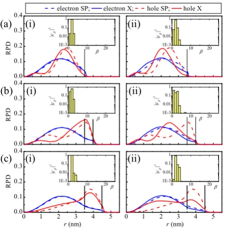
1S1(e/)21S3(h/)2exciton: In the case of a core-only CdSe QD and no dielectric confinement, correlation causes both carriers to move towards the centre of the QD compared to their SP counterparts, Fig. 10(a,i). This is purely a result of the direct interparticle Coulomb interaction, giving correlation energies of approximately 5 meV. In-troduction of the self-polarization potential, i.e. "="(r), further exaggerates this move of RPDs of both carriers away from the QD surface in the core-only CdSe QD, Fig. 10(a,ii). This e↵ect increases localisation of both
0 1 2 3
-60 -50 -40 -30 -20 -10 0
0 1 2 3
0 1 2 3
0.0 0.5 1.0
(b)
(a)
E co
rr
(
m
eV
)
a s (nm)
ε =const.
ε =ε(r)
1s(h)
3/2 LB 2s(h)
3/2 LB
a s (nm) ps
[image:9.595.63.287.60.289.2]as (nm)
FIG. 9: Ecorr of (a) 1S1/2(e)1S3/2(h) and (b) 1S1/2(e)2S3/2(h) excitons inac= 3.5 nm CdSe/CdTe QDs along the linel2 in Fig. 6. Cases of"= const.and"="(r) are represented by open and solid symbols respectively. The inset showsps for the 2s(h)3/2 SP state.
carriers near the centre of QD, increasing their overlap and giving correlation energiesEcorr= 18 meV. For the
1S1(e/)21S3(h/)2 exciton in the CdSe QD the shift in RPD is
mainly due to an increase in 2s(1e/)21s(3h/)2( = 26) charac-ter.
To assess the e↵ect of dielectric confinement on the cor-related carriers in the CdSe QD we consider the expec-tation value of the 1s electron (hole) radial coordinate, denoted hrµi. When " = const. (no self-polarization) we find hrhi = 1.55 nm compared to hrhi = 1.44 nm when"="(r) for the 1s3(h/)2state. In contrast the e↵ect
of dielectric confinement moves the 1s(1e/)2 electron from
hrei= 2.01 nm to hrei = 1.89. Although the SP 1s(1e/)2 RPD has significantly greater overlap with the repulsive peak in self-polarization potential near the QD surface than the SP 1s(3h/)2 hole RPD, the correlated electron is shifted by dielectric confinement by almost the same dis-tance as the correlated hole. These results reflect the larger sensitivity of the correlated hole wave function to the dielectric environment compared to the electron in the CdSe core-only QD.
[image:9.595.326.546.61.213.2]the 1s(3h/)2 state is close to the value of QD’s outermost radius,ac+as.
The close proximity of the hole to QD surface reduces the distance ⇠ = hrQDh i hrhimagei between the hole in the QD and its mirror image in the colloid, dramati-cally increasing the Coulombic repulsion between them which scales as/1/⇠. Such repulsion causes the hole to be pushed back towards the centre of the QD, thereby dramatically increasing overlap with the correlated elec-tron wave function. The presence of dielectric confine-ment means the exciton wave function is an almost equal superposition of the 1s(1e/)2ns3(h/)2 (n = 1,2) states, with
|c1|2 = 0.449 and |c2|2 = 0.458 (inset in Fig. 10(b,ii)).
For comparison, when"= const.the 1s1(e/)22s(3h/)2 charac-ter amounts to only |c2|2 = 0.019. The much stronger
configuration mixing in the dielectric confinement case allows Ecorr to reach⇠ 62 meV, compared to -9 meV
without dielectric confinement.
Further increase of the CdSe/CdTe QD shell thickness toas = 1 nm allows the SP hole to fully localize in the shell while the SP electron stays in the core, reaching the type-II localisation limit. The carriers e↵ectively en-ter the strong confinement regime in which the Coulomb e↵ects are overridden by the e↵ects of the type-II spa-tial confinement. In the SCA⇢eX(h)' ⇢eSP(h), and the ef-fect of correlations is lost. Again,Ecorr is only non-zero
when the hole is delocalized; once it localizes in the shell, the e↵ect of VBM confinement overrides the interparticle Coulomb attraction. Dielectric confinement only slightly shifts the hole density towards the core, resisted by the opposing e↵ect of spatial confinement with Ecorr ⇡ 3
meV foras>1.5 nm.
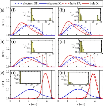
1S1(e/)22S3(h/)2 exciton: In the absence of dielectric mis-match ("= const.) the interparticle Coulomb interaction mainly causes the hole to move towards the core whilst the electron is nearly una↵ected, Fig. 11(a-c,i). Intro-ducing dielectric confinement systematically moves the hole RPD towards the centre of the QD, whilst the elec-trons are again minimally a↵ected, Fig. 11(a-c,ii). Dielec-tric confinement has the most pronounced e↵ect on the
as= 0.5 nm QD for which the self-polarization potential is able to almost completely repel the hole RPD from the shell to the core region, Fig. 11(b,ii); this is associated with an increase of|Ecorr|to 36 meV. The movement of
the correlated hole RPD to the centre of the QD upon introduction of dielectric confinement is due to the mix-ing of 1s(1e/)2ns3(h/)2(n= 1,2) EHPs into the exciton wave function. For the as = 1 nm QD the competing e↵ects of type-II VBM profile, interparticle Coulomb attraction and self-polarization potential lead to the correlated hole RPD being delocalized across the whole QD with a lo-cal maximum in both the core and shell. Whenas is in-creased to 1.5 nm and beyond, the SCA regime is reached and the correlated RPDs are very close to those of the uncorrelated states (not shown).
[image:10.595.320.542.62.289.2]Generally we have observed when the correlated wave
FIG. 10: Solid (dashed) lines represent RPDs of the 1S(e)1/21S3/2(h) exciton (1s(e)1/21s(h)3/2 EHP) of CdSe/CdTe QDs with ac = 3.5 nm and (a) as = 0, (b) as = 0.5 nm, and (b)as = 1 nm for (i) " = const.and (ii) " = "(r). Verti-cal lines denote the boundaries between the core, shell and external medium. Insets are barcharts of|c |2 characters.
functions are in the type-II localization regime the charge that localizes in the QD’s shell is a↵ected more by the interparticle Coulomb attraction, whilst the innermost confined charge carrier is barely a↵ected. We explain this behavior from the fact thats(1e/)2electron states are largely
spherically symmetric, Fig. 2(a) and core-localizeds(3h/)2
hole states are approximately spheroidal, see Fig. 2(b). Gauss’s Law means that hole charge density⇢h
X at some radius rh is not a↵ected any more by electron charge density⇢e
X situated atr > rh.
E. Exciton optical dipole matrix elements
The regions of largest | P2
X| in Fig. 12 closely coin-cide with the regions of largest |Ecorr| in Fig. 6 since
the greater the change in carrier density due to correla-tion the greater the change in electron-hole wave funccorrela-tion overlap. However, the correlation can increase or de-crease the dipole matrix element of a particular exciton state relative to the SCA depending on the localization regime of the uncorrelated charge carriers.
Correlation only slightly changes the dipole matrix el-ements of the 1S1(e/)21S3(h/)2CdTe/CdSe QD exciton, which is consistent with the similarity of the correlated and un-correlated carrier RPDs in Fig. 8. For the CdTe/CdSe QD we see that when"= const. the P2
FIG. 11: Solid (dashed) lines represent RPDs of the 1S1/2(e)2S(h)3/2 exciton (1s(e)1/22s(h)3/2 EHP) of CdSe/CdTe QDs with ac = 3.5 nm and (a) as = 0, (b) as = 0.5 nm, and (b) as = 1 nm for (i) " = const. and (ii) " = "(r). Verti-cal lines denote the boundaries between the core, shell and external medium. Insets are barcharts of|c |2 characters.
closely follows the 1s(3h/)2LB (see Fig. 12(a,i)), indicating
that the 1s(3h/)2 hole should be delocalized (or approxi-mately so) for correlation to reduce the dipole matrix element relative to the uncorrelated EHP. Once the hole localises in the core P2
X becomes positive. Similar be-haviour is seen when"="(r), except that P2
X can be slightly negative for QDs with thin shells,as.0.5 nm.
Figures 12(a,iii-iv) show a similar trend for the CdSe/CdTe QD, with P2
X only being negative when the 1s(3h/)2 hole is delocalized; this is particularly noticeable for CdSe/CdTe QDs withac&1.5 nm when"="(r) in Fig. 12(a,iv). As the shell width increases for a particular core size P2
X increases dramatically near the 1s
(h) 3/2LB,
due to the interparticle Coulomb interaction that pre-vents the hole wave function localizing in the shell and dramatically increases its overlap with the electron wave function in the core, Fig. 10(b). This e↵ect is enhanced by dielectric confinement, shown by the larger brighter area in Fig. 12(a,iv) above the hole LB. The di↵erence
P2
X reaches a maximum value of 0.15 for an ac = 3.5 nm, as = 0.75 nm QD when " = "(r), compared to a maximum value of 0.042 (for anac = 3 nm,as = 0.625 nm QD) when " = const.. These shifts represent an increase by a factor of 7.29 and 1.5 in the dipole matrix element respectively relative to the SCA results found us-ing FOPT. Both regions of positive P2
X seen in Fig. 12 (a,iii-iv) near the hole LB are mainly due to the mixing
of the 1s(1e/)22s(3h/)2EHP which becomes a large component of the exciton wave function.
The e↵ect of correlation in the 1S1(e/)22S3(h/2)exciton leads
to reduction of dipole matrix element near the 2s(3h/)2 LB in both the CdTe/CdSe and CdSe/CdTe QDs. This is most clearly seen for the CdSe/CdTe QD in Fig. 12(b,iii-iv), for which the reduction in the contribution of the 1s(1e/)22s(3h/)2 EHP leads to the an area of negative P2
X. These areas roughly coincide with the regions of positive
P2
Xin Fig. 12(a,iii-iv), suggesting a transfer of oscillator strength from the 1S1(e/)21S3(h/)2to 1S1(e/)22S(3h/2) CdSe/CdTe QD exciton.
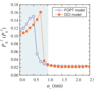
The P2
X reaches its maximum value for anac = 3.5 nm and as = 0.75 nm QD, Fig. 13. At this point the radiative recombination time of the 1S1(e/)21S3(h/)2 exciton calculated with FOPT (⌧FOPT
rad. = 13.4 ns) is about one order of magnitude larger than that calculated with DCI (⌧DCI
rad. = 2.85 ns). This reflects the need of proper treat-ment of correlation e↵ects in the design of optoelectronic devices that rely on dynamic process between charges.
We also found that the e↵ect of correlation on the CdSe/CdTe QDs exciton dipoles and radiative lifetimes strongly depends on the dielectric properties of the exter-nal medium. In Table I we list radiative times calculated with and without correlation for several values of"3. The
first two rows correspond to the spatially varying dielec-tric constant"="(r) whilst the third row corresponds to
"= const., i.e. the case without dielectric confinement. Generally as"3 is increased and the dielectric mismatch
between the QD and the external medium falls we see that the e↵ect of correlation on the radiative lifetimes becomes less important. However for the case of a QD
in vacuoor air ("3= 1) and commonly used solvents like
toluene or hexane ("3⇡2), the e↵ect of correlations on
[image:11.595.316.555.566.615.2]the radiative lifetime cannot be neglected.
TABLE I: Radiative lifetimes of CdSe/CdTe QDs withac= 3.5 nm and di↵erent dielectric environments. The second col-umn shows shell widths for which P2
Xreaches its maximum:
⌧FOPT
rad. obtained neglecting the correlation e↵ects and⌧rad.DCI in-cluding them.
"3 as(nm) ⌧radFOPT (ns) ⌧radDCI(ns)
1 0.80 38.6 7.66
2 0.75 13.4 2.85
6.65 0.55 1.55 0.96
FIG. 12: The change P2
Xin the optical dipole matrix element due to correlation for (a) the 1S1/2(e)1S (h)
3/2and (b) the 1S (e) 1/22S
(h) 3/2 exciton in CdTe/CdSe and CdSe/CdTe QDs. (i) and (iii) corresponds to"= const., whilst (ii) and (iv) corresponds to"="(r), respectively. Electron (hole) LBs are shown as blue (red) lines.
0.0 0.5 1.0 1.5 2.0 2.5
0.00 0.02 0.04 0.06 0.08 0.10 0.12 0.14 0.16 0.18
FOPT model DCI model
PX
2 (
P0
2 )
a
s (nm)
FIG. 13: The dipole matrix elements calculated in FOPT (open circles) and the DCI scheme (solid squares) for CdSe/CdTe QDs withac= 3.5 nm as a function of the shell thickness for the 1S1/2(e)1S3/2(h) exciton. The shaded area shows the region ofasin which correlation has the greatest e↵ect.
IV. CONCLUSIONS
We developed a computationally efficient decoupled CI scheme to examine the correlation energy Ecorr and
the change in optical dipole matrix element P2
X of the
1S1(e/)2nS3(/h2)(n= 1,2) excitons as a function of core radius and shell width in type-II CdTe/CdSe and CdSe/CdTe core/shell QDs. We have found: (i) The QD designs which gave the largest magnitude Ecorr values for the
1S1(e/)2nS3(/h2)(n= 1,2) excitons were associated with
delo-calizedns(3h/)2hole states. In CdSe/CdTe QDs the largest magnitude correlation energy found is the consequence of strong configuration mixing of the 1s(1e/)21s(3h/)2 and
1s(1e/)22s(3h/)2 EHPs in the excitonic wave function caused by dielectric mismatch. (ii) The dielectric confinement mainly a↵ected QDs in the type-I and quasi-type-II lo-calization regimes, particularly those QDs for which the corresponding SP hole states are delocalized. (iii) Over-all CdSe/CdTe QDs were a↵ected more by dielectric en-vironment than CdTe/CdSe QDs, as they tend to lo-calize holes in the shell closer to the repulsive peak in the self-polarization potential that arises from dielectric mismatch. We conclude that the correlated holes are more a↵ected by dielectric confinement than the elec-trons due to the much larger density of states in the VB. (iv) The regions of (ac, as)- space with the largest PX2 corresponded to regions in which |Ecorr| was greatest.
[image:12.595.94.248.405.550.2]strength and radiative lifetime of excitons in CdSe/CdTe core/shell QDs.
In contrast to epitaxially grown QDs, which largely correspond to " = const. case in our analysis, our re-sults show that the charge separation due to the type-II band alignments and by dielectric mismatch induces self-polarization in core/shell colloidal QDs leads to strong deviations from the SCA for the exciton wave function.
Acknowledgements
The authors acknowledge the EPSRC UK grant ”En-hanced multiple exciton generation in colloidal quan-tum dots” (EP/K008587/1) for financial support. We also acknowledge the EU-COST project ”MultiscaleSo-lar” (MP1406) and The Great Britain Sasakawa Foun-dation. We wish to thank Jason Smith and David Binks for useful discussions.
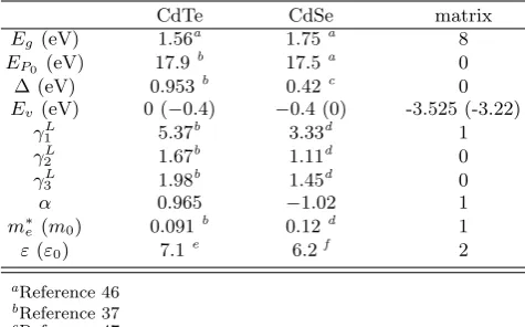
Appendix
The SP and excitonic states were calculated using the parameters in Table II whereEg denotes the bulk band gap, the Kane energy is EP0 = 2m0P
2
0/~2, P0 is the
bulk interband momentum matrix element, m0 is the
free electron mass,41 is the spin-orbit splitting and
Ev is the VBM energy. The Luttinger parameters are L
i (i= 1,2,3),↵ is a CB parameter andm⇤e represents the electron e↵ective mass at the bottom of the CB,37"
is the dielectric constant given in the units of free space permitivity, "0. Modified Luttinger parameters for the
[image:13.595.316.554.175.323.2]VB were calculated in the spherical approximation.36
TABLE II: The (2,6)-bandk·pparameters. Ev correspond to the CdTe/CdSe (CdSe/CdTe) VB o↵sets.
CdTe CdSe matrix
Eg (eV) 1.56a 1.75a 8
EP0 (eV) 17.9
b 17.5a 0
(eV) 0.953b 0.42c 0
Ev (eV) 0 ( 0.4) 0.4 (0) -3.525 (-3.22) L
1 5.37b 3.33d 1
L
2 1.67b 1.11d 0
L
3 1.98b 1.45d 0
↵ 0.965 1.02 1
m⇤
e (m0) 0.091b 0.12d 1
"("0) 7.1e 6.2f 2
aReference 46
bReference 37
cReference 47
dReference 48
eReference 49
fReference 50
⇤ Electronic address: [email protected];Phone:
+44(0)1612-953847
1 Pal, B. N.; Ghosh, Y.; Brovelli, S.; Laocharoensuk, R.;
Klimov, V. I.; Hollingsworth, J. A.; Htoon, H. Giant CdSe/CdS Core/Shell nanocrystal quantum dots as effi -cient electroluminescent materials: strong influence of shell thickness on light-emitting diode performance.Nano Lett.
2012,12, 331–336.
2 Kamat, P. V. Quantum dot solar cells: semiconductor
nanocrystals as light harvesters.J. Phys. Chem. C 2008, 112, 18737–18753.
3 Sukhovatkin, V.; Hinds, S.; Brzozowski, L.; Sargent, E. H. Colloidal Quantum-dot photodetectors exploiting multiex-citon generation.Science 2009,324, 1542–1544.
4 Konstantatos, G.; Sargent, E. H. Nanostructured materi-als for photon detection.Nature Nanotechnology 2010,5, 391–400.
5 Caruge, J.-M.; Chan, Y.; Sundar, V.; Eisler, H. J.;
Bawendi, M. G. Transient photoluminescence and simul-taneous amplified sponsimul-taneous emission from multiexciton states in CdSe quantum dots. Phys. Rev. B 2004, 70, 085316.
6 Klimov, V. I.; Ivanov, S. A.; Nanda, J.; Achermannn, M.;
Bezel, I.; McGuire, J. A.; Piryatinski, A. Single-exciton optical gain in semiconductor nanocrystals.Nature2007, 447, 441–446.
7 Shabaev, A.; Efros, A. L.; Nozik, A. J. Multiexciton
gener-ation by a single photon in nanocrystals.Nano Lett.2006, 6, 2856–2863.
8 Semonin, O. E.; Luther, J. M.; Choi, S.; Chen, H.-Y.; Gao, J.; Nozik, A. J.; Beard, M. C. Peak external pho-tocurrent quantum efficiency exceeding 100% via MEG in a quantum dot solar cell.Science 2011,334, 1530–1533. 9 Trinh, M. T.; Polak, L.; Schins, J. M.;
Houte-pen, A. J.; Vaxenburg, R.; Maikov, G. I.; Grinbom, G.; Midgett, A. G.; Luther, J. M.; Beard, M. C.; Nozik, A. J.; Bonn, M.; Lifshitz, E.; Siebbeles, L. D. A. Anomalous inde-pendence of multiple exciton generation on di↵erent group IV-VI quantum dot architectures. Nano Lett.2011, 11, 1623–1629.
10 Ithurria, S.; Tessier, M. D.; Mahler, B.; Lobo, R. P. S. M.; Dubertret, B.; Efros, A. L. Colloidal nanoplatelets with two-dimensional electronic structure.Nature
Materi-als2011,10, 936–941.
11 Jasieniak, J.; Califano, M.; Watkins, S. E. Size-dependent valence and conduction band-edge energies of semiconduc-tor nanocrystals.ACS Nano2011,5, 5888–5902. 12 Kim, S.; Fisher, B.; Eisler, H.-J.; Bawendi, M.
Type-II quantum dots: CdTe/CdSe(core/shell) and CdSe/ZnTe(core/shell) heterostructures. J. Am. Chem.
Soc.2003,125, 11466–11467.
13 Li, J. J.; Tsay, J. M.; Michalet, X.; Weiss, S. Wavefunction
engineering: from quantum wells to near-infrared type-II colloidal quantum dots synthesized by layer-by-layer col-loidal epitaxy.Chem. Phys.2005,318, 82 – 90.
14 Xie, R.; Kolb, U.; Li, J.; Basch´e, T.; Mews, A.
Am. Chem. Soc.2005,127, 7480–7488.
15 Piryatinski, A.; Ivanov, S. A.; Tretiak, S.; Klimov, V. I. Ef-fect of quantum and dielectric confinement on the exciton-exciton interaction energy in type II core/shell semicon-ductor nanocrystals.Nano Lett.2007,7, 108–115. 16 Kumar, S.; Jones, M.; Lo, S.; Gregory D.Scholes, Nanorod
heterostructures showing photoinduced charge separation. Small 2007,3, 1633–1639.
17 Zhong, H.; Zhou, Y.; Yang, Y.; Yang, C.; Li, Y. Syn-thesis of type II CdTe-CdSe nanocrystal heterostructured multiple-branched rods and their photovoltaic applica-tions.J. Phys. Chem. C 2007,111, 6538–6543.
18 Itzhakov, S.; Shen, H.; Buhbut, S.; Lin, H.; Oron, D.
Type-II quantum-dot-sensitized solar cell spanning the visible and near-infrared spectrum.J. Phys. Chem. C 2013,117, 22203–22210.
19 McElroy, N.; Page, R.; Espinbarro-Valazquez, D.;
Lewis, E.; Haigh, S.; O’Brien, P.; Binks, D. Comparison of solar cells sensitised by CdTe/CdSe and CdSe/CdTe core/shell colloidal quantum dots with and without a CdS outer layer.Thin Solid Films 2014,560, 65 – 70. 20 Brovelli, S.; Schaller, R. D.; Crooker, S. A.;
Garcia-Santamaria, F.; Chen, Y.; Viswanatha, R.; Hollingsworth, J. A.; Htoon, H.; Klimov, V. I. Nano-engineered electron-hole exchange interaction controls exciton dynamics in core-shell semiconductor nanocrystals. Nature Communications 2011,2, 280.
21 Oron, D.; Kazes, M.; Banin, U. Multiexcitons in type-II colloidal semiconductor quantum dots.Phys. Rev. B2007, 75, 035330.
22 McDonald, P. G.; Tyrrell, E. J.; Shumway, J.; Smith, J. M.;
Galbraith, I. Tuning biexciton binding and antibinding in core/shell quantum dots.Phys. Rev. B2012,86, 125310. 23 Ivanov, S. A.; Nanda, J.; Piryatinski, A.; Achermann, M.; Balet, L. P.; Bezel, I. V.; Anikeeva, P. O.; Tretiak, S.; Klimov, V. I. Light amplification using inverted core/shell nanocrystals: towards lasing in the single-exciton regime. J. Phys. Chem. B 2004,108, 10625–10630.
24 Nanda, J.; Ivanov, S. A.; Achermann, M.; Bezel, I.;
Piry-atinski, A.; Klimov, V. I. Light amplification in the single-exciton regime using single-exciton-single-exciton repulsion in type-II nanocrystal quantum dots.J. Phys. Chem. C 2007,111, 15382–15390.
25 Szabo, A.; Ostlund, N. S.Modern quantum chemistry:
in-troduction to advanced electronic structure theory; Dover Publications, Inc., 1982.
26 Fonoberov, V. A.; Pokatilov, E. P.; Balandin, A. A. Exci-ton states and optical transitions in colloidal CdS quantum dots: Shape and dielectric mismatch e↵ects.Phys. Rev. B
2002,66, 085310.
27 Men´endez-Proupin, E.; Trallero-Giner, C. Electric-field and exciton structure in CdSe nanocrystals. Phys. Rev.
B 2004,69, 125336.
28 Vukmirov´c, N.; Tomi´c, S. Plane wave methodology for
sin-gle quantum dot electronic structure calculations.Journal of Applied Physics2008,103, 103718.
29 Califano, M.; Franceschetti, A.; Zunger, A. Lifetime and polarization of the radiative decay of excitons, biexcitons, and trions in CdSe nanocrystal quantum dots.Phys. Rev.
B 2007,75, 115401.
30 Korkusinski, M.; Voznyy, O.; Hawrylak, P. Fine structure and size dependence of exciton and biexciton optical spec-tra in CdSe nanocrystals.Phys. Rev. B 2010,82, 245304. 31 Allan, G.; Delerue, C. Tight-binding calculations of the
op-tical properties of HgTe nanocrystals.Phys. Rev. B 2012, 86, 165437.
32 Efros, A. L.; Rosen, M. The electronic structure of
semi-conductor nanocrystals. Annual Review of Materials
Sci-ence 2000,30, 475–521.
33 Franceschetti, A.; Williamson, A.; Zunger, A. Addition spectra of quantum dots: the role of dielectric mismatch. J. Phys. Chem. B2000,104, 3398–3401.
34 Climente, J. I.; Royo, M.; Movilla, J. L.; Planelles, J. Strong configuration mixing due to dielectric confine-ment in semiconductor nanorods.Phys. Rev. B 2009,79, 161301.
35 Brus, L. E. Electron-electron and electron-hole interactions
in small semiconductor crystallites: The size dependence of the lowest excited electronic state.J. Chem. Phys.1984, 80, 4403–4409.
36 Pokatilov, E. P.; Fonoberov, V. A.; Fomin, V. M.;
De-vreese, J. T. Development of an eight-band theory for quantum dot heterostructures. Phys. Rev. B 2001, 64, 245328.
37 Efros, A. L.; Rosen, M. Quantum size level structure of
narrow-gap semiconductor nanocrystals: e↵ect of band coupling.Phys. Rev. B1998,58, 7120–7135.
38 Bolcatto, P. G.; Proetto, C. R. Partially confined excitons in semiconductor nanocrystals with a finite size dielectric interface.J. Phys.: Condens. Matter2001,13, 319. 39 Tyrrell, E. J.; Smith, J. M. E↵ective mass modeling of
excitons in type-II quantum dot heterostructures. Phys. Rev. B2011,84, 165328.
40 Brus, L. E. A simple model for the ionization
poten-tial, electron affinity, and aqueous redox potentials of small semiconductor crystallites.J. Chem. Phys.1983,79, 5566–5571.
41 Efros, A. L.; Rosen, M.; Kuno, M.; Nirmal, M.; Nor-ris, D. J.; Bawendi, M. Band-edge exciton in quantum dots of semiconductors with a degenerate valence band: Dark and bright exciton states.Phys. Rev. B 1996, 54, 4843– 4856.
42 Gong, K.; Zeng, Y.; Kelley, D. F. Extinction coefficients,
oscillator strengths, and radiative lifetimes of CdSe, CdTe, and CdTe/CdSe nanocrystals. J. Phys. Chem. C 2013, 117, 20268–20279.
43 Ma, X.; Mews, A.; Kipp, T. Determination of electronic energy levels in type-II CdTe-core/shell and CdSe-core/CdTe-shell nanocrystals by cyclic voltammetry and optical spectroscopy.J. Phys. Chem. C2013,117, 16698– 16708.
44 Cai, X.; Mirafzal, H.; Nguyen, K.; Leppert, V.; Kel-ley, D. F. Spectroscopy of CdTe/CdSe type-II nanostruc-tures: morphology, lattice mismatch, and band-bowing ef-fects.J. Phys. Chem. C 2012,116, 8118–8127.
45 Tomi´c, S. E↵ect of Sb induced type II alignment on dy-namical processes in InAs/GaAs/GaAsSb quantum dots: Implication to solar cell design. Appl. Phys. Lett. 2013, 103, 072112.
46 de Mello Doneg´a, C.; Koole, R. Size dependence of the spontaneous emission rate and absorption cross section of CdSe and CdTe quantum dots.J. Phys. Chem. C 2009, 113, 6511–6520.
47 Norris, D. J.; Bawendi, M. G. Measurement and assign-ment of the size-dependent optical spectrum in CdSe quan-tum dots.Phys. Rev. B1996,53, 16338–16346.
48 Schulz, S.; Czycholl, G. Tight-binding model for
49 Rowe, J. M.; Nicklow, R. M.; Price, D. L.; Zanio, K. Lattice dynamics of cadmium telluride. Phys. Rev. B 1974, 10, 671–675.
50 Wang, L.-W.; Zunger, A. Pseudopotential calculations of
nanoscale CdSe quantum dots. Phys. Rev. B 1996, 53, 9579–9582.
51 The factor of 1
4 comes from the Clebsch-Gordan coefficient
in Eq. 5 whenL=Lz = 1, je = 12,me = 12,jh = 32 and
mh= 12
52 Additional calculations for the 1S(e) 1/2nS
(h)