International Journal of Emerging Technology and Advanced Engineering
Website: www.ijetae.com (ISSN 2250-2459, ISO 9001:2008 Certified Journal, Volume 7, Issue 2, February 2017)
108
Study and Analysis of Window Synchronization in Coherent
Optical OFDM
S. Balaji
1, N. Sangeetha
2, G. Sundara Kishore
31 ,2,3
School of Electronics Engineering, VIT University, Vellore, Tamilnadu, India
Abstract—To analyse the errors that are involved during
transmission through optical fibers using OFDM techniques. We analyze the errors that affect the long haul transmission of data with high data rate in optical fibers. These errors are termed synchronization errors. We determine various parameters that affect the performance and use them for comparison and analysis.
Keywords- OFDM – Orthogonal frequency division
multiplexing; timing metric – measured in seconds; timing offset; window synchronization; Schmidl and Cox algorithm.
I. INTRODUCTION
Due to the increase in the number of users around the globe, long distance transmission of data has become a challenging aspect. With the increase in the net transmission data rates over the years, long distance transmission has become a challenge. There used to be single carrier techniques used for transmission and reception of data. But the drawback was its inability to transmit long distances with high data rate and also increase in data traffic. The data rate was limited to 10Gb/s. This led to introducing coherent optical OFDM techniques into optical fiber communication system. The idea of CO-OFDM was chosen because of its attractive modulation format for long-haul transmission. Uniqueness of signal processing is always considered to be one of the central features of OFDM.
Generally after transmission of signal through optical fiber, the signal is distorted and rotated due to the influence of phase noise and chromatic dispersion. In this paper we compare the ideal results with phase noise results.
T. Schmidl and D. Cox’s algorithms use correlation of training symbol to realize the synchronization.
In this paper, we formulate schmidl and cox algorithm and then determine the mean, variance and timing metric and compare their performances. We also compare the results by introducing phase noise.
II. CO-OFDMSYSTEM DESCRIPTION
OFDM plays a significant role in the modem telecommunications for both wireless and wired communications.
Orthogonal Frequency Division Multiplexing (OFDM) technique where the channel capacity is further increased and also leads to a further reduction in the cost of the bandwidth. OFDM is used now-a-days for wireline applications due to its high data rate transmission capability with high bandwidth efficiency. Figure 1 shows the block diagram of a basic OFDM system.
[image:1.612.324.571.368.584.2]In OFDM, different data signals are modulated with different carriers simultaneously. Till date, this has proven to be an efficient technique for long haul optical fiber communication systems.
Figure 1: Block Diagram of OFDM system
International Journal of Emerging Technology and Advanced Engineering
Website: www.ijetae.com (ISSN 2250-2459, ISO 9001:2008 Certified Journal, Volume 7, Issue 2, February 2017)
109
The signal is represented as s(t), given by
where cki is the ith information symbol at the kth subcarrier, sk is the kth subcarrier waveform, the number of subcarriers is Nsc, fk is the frequency of the subcarrier, and
Ts is the symbol period. Therefore, the detected information symbol
A. Spectral Efficiency of CO- OFDM
In CO-OFDM systems, Nsc subcarriers are transmitted in every OFDM symbol period of Ts. Thus the total symbol rate R for CO-OFDM systems is given by
We use the bandwidth of the first null to denote the boundary of each wavelength channel. The OFDM bandwidth, BOFDM is thus given by
where ts is the observation period. Assuming a large number of subcarriers used, the bandwidth efficiency of OFDM η is found to be
The factor of 2 accounts for two polarizations in the fiber.
III. CO-OFDMSYNCHRONISATION DESCRIPTION
In the RF OFDM receiver, this technique has also faced many errors at the receiver side. The transmitted data from the fiber is first down—converted to RF signal. The RF signal while undergoing demodulation can give rise to three kinds of errors called as synchronization errors. There are three types of synchronization: 1) DFT Window Synchronization 2) Frequency Synchronization 3) Sub carrier recovery. Generally, OFDM gets influenced by phase noise and chromatic dispersion.
The improper synchronization between the local oscillator of the transmitter and receiver adds phase noise to the signal. This type of improper synchronization makes the receiver insensitive to timing offset.
DFT window timing synchronization corresponds to symbol timing synchronization in single carrier transmission. Accurate synchronization often requires accurate estimation, so some estimation methods are also investigated in this chapter. We have used Schmidl’s DFT window timing/frequency offset estimation method and presented the theoretical analysis and computer simulation results. Frequency offset may result from a mismatch of local oscillator frequency between transmitter and receiver. OFDM have high sensitivity to synchronisation errors. Synchronisation errors can cause
1) Inter-symbol interference (ISI) 2) Inter-carrier interference (ICI)
A. Schmidl and Cox Algorithm
In our project we are actually investigating the performance of a robust and efficient technique for frame/symbol timing synchronization in coherent optical OFDM. This is done using schmidl and cox algorithm. Schmidl and Cox proposed a rapid synchronization method for orthogonal frequency division multiplexing using either continuous transmission or burst operation over a selective frequency channel. The presence of a signal can be detected upon the receipt of just on training sequence of two symbols. The start of the frame and beginning of the symbol can be found, and carrier frequency offsets of many subchannel spacings can be corrected. The correlation function can be normalized to its maximum value given by:
And
International Journal of Emerging Technology and Advanced Engineering
Website: www.ijetae.com (ISSN 2250-2459, ISO 9001:2008 Certified Journal, Volume 7, Issue 2, February 2017)
110
IV. SIMULATION AND RESULT
We have conducted a matlab simulation for the coherent optical OFDM presented in figure 1 to confirm the DFT window synchronization using the Schmidl format for a COOFDM system at 10 Gb/s under the influence of chromatic dispersion, linewidth, and optical-to-signal noise ratio (OSNR).
Table I. Simulation Parameters
Modulation QAM
FFT size 256 L (no. of samples of training symbols)
512
No. of bits / samples 4 No. of symbols 100 Number of frames 100
Data Rate 10 b/s
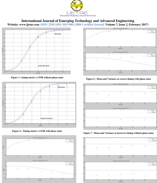
A. Timing metric VS SNR
Timing metric is the measure of the timing interval of detection of the symbol the DFT window using metric systems. The timing metric here is used to determine whether the training sequence has been received at the correct timing or not. We know the SNR compares the level of the signal with the background noise. In the figure, the graph is plotted by comparing the timing metric with respect to the SNR levels of the system for the ideal case. Figures 3 and 4 show the comparison.
From the graph we could observe that after phase noise is taken into account, there exists slight deviation from the ideal graph as shown in figure. Here a little more increase in SNR value gives the best timing.
B. Phase Noise
Phase noise is the noise caused by the random variation of the phase in the down converted received signal. It is mainly caused by time domain instabilities. Here in our simulation we have introduced phase noise and checked mean and variance. We have also plotted a graph (timing metric Vs SNR) to check how phase noise influences our algorithm.
C. Mean and Variance at correct timing
Correct timing is the exact timing at which the DFT window detects the correct symbol. Mean and Variance are used due to the effects of degradation in performance, if the symbol timing estimate deviates from the correct region. We plot mean vs SNR for correct timing and incorrect timing of signal detection by DFT window and we infer from the results. The results are shown in figures 5 and 6. From the above figure, we observe that there is an increase in the mean value with an increase in SNR which proves that the probability of the signal being detected at the right time is high for a very high SNR. Once phase noise is introduced, the mean and variance curves are deviated from the ideal curve
.
After 20db SNR the mean stays gradually increases and gets closer to the maximum value 1. We could see that the variance fluctuates because of the phase noise.D. Mean and Variance at incorrect timing
International Journal of Emerging Technology and Advanced Engineering
Website: www.ijetae.com (ISSN 2250-2459, ISO 9001:2008 Certified Journal, Volume 7, Issue 2, February 2017)
[image:4.612.42.574.42.660.2]111
Figure 3 : timing metric vs SNR without phase noise
Figure 4 : Timing metric vs SNR with phase noise
[image:4.612.320.576.110.298.2]Figure 5 : Mean and Variance at correct timing without phase noise
[image:4.612.323.577.319.483.2]Figure 6 : Mean and Variance at correct timing with phase noise
Figure 7 : Mean and Variance at incorrect timing without phase noise
[image:4.612.326.578.504.661.2]International Journal of Emerging Technology and Advanced Engineering
Website: www.ijetae.com (ISSN 2250-2459, ISO 9001:2008 Certified Journal, Volume 7, Issue 2, February 2017)
112
V. CONCLUSION
Thus we have performed the window synchronization in CO-OFDM and determined it performance with the increase in the SNR value. It is seen that for an increase in the SNR value, there leads to an increase in the timing metric. From this we can infer that the symbol has higher probability to be detected by the DFT window at high SNR. But considering the phase noise some parts of the signal still deviates from the the actual mean value. Further introduction of Chromatic dispersion can also influence the value of timing metric.
REFERENCES
[1] Shieh.W,Yang.Q, and MA.Y.107 Gb/s coherent optical ofdm transmission over 1000km SSMF fiber using orthogonal band multiplexing, optics express,16(9),6378–6386 (2008).
[2] Schmidl TM, Cox DC. Robust frequency and timing synchronization for OFDM. IEEE Trans Commun 1997;45:1613–21.
[3] W. Shieh, X. Yi, and Y. Tang, ―Transmission experiment of multi-gigabit coherent optical OFDM systems over 1000 km SSMF fiber,‖ Electron. Lett. 43, 183-185 (2007). R. E. Haskell and C. T. Case, ―Transient signal propagation in lossless isotropic plasmas (Report style),‖ USAF Cambridge Res. Lab., Cambridge, MA, Rep. ARCRL-66-234 (II), 1994, vol. 2.
[4] I. B. Djordjevic and B. Vasic, ―Orthogonal frequency division multiplexing for high-speed optical transmission,‖ Opt. Express 14, 3767–3775 (2006)., 3rd ed., Western Electric Co., Winston-Salem, NC, 1985, pp. 44–60
[5] B. Sheng, J. Zheng, X. You and L. Chen, "A Novel Timing Synchronization Method for OFDM Systems," in IEEE Communications Letters, vol. 14, no. 12, pp. 1110-1112, December 2010.
[6] S. Diggavi, ―Analysis of multicarrier transmission in time-varying channels‖, in Communications, 1997. ICC ’97 Montreal, Towards the Knowledge Millennium. 1997 IEEE International Conference on, vol. 3, 1997,pp. 1191–1195 vol.3.
[7] Y. S. Cho, MIMO-OFDM wireless communications with MATLAB.Singapore; Hoboken, NJ: IEEE Press: J. Wiley & Sons (Asia), 2010.[Online]. Available: http://site.ebrary.com/id/10412611 [8] H. Minn, M. Zeng, and V . Bhargava, ―On timing offset estimation forofdm systems,‖ Communications Letters, IEEE, vol. 4, no. 7, pp. 242–244, 2000.
[9] G. Acosta, ―OFDM simulation using matlab,‖ Georgia Institute of Technology, Smart Antenna Research Laboratory, Tech. Rep.,
Aug.2000. [Online]. Available:
http://www.ece.gatech.edu/research/labs/sarl/tutorials/OFDM/Tutori al web.pdf
[10] M. Speth, F. Classen, and H. Meyr, ―Frame synchronization of ofdmsystems in frequency selective fading channels,‖ in Vehicular Technology Conference, 1997, IEEE 47th, vol. 3, 1997, pp. 1807– 1811 vol.3.