International Journal of Emerging Technology and Advanced Engineering
Website: www.ijetae.com (ISSN 2250-2459,ISO 9001:2008 Certified Journal, Volume 5, Issue 9, September 2015)
158
“Analysis of Technology used in an Innovative Hybrid
Conventional I. C. Engine For Vehicle. to Next Generation-
A Multi Hybrid Car with Zero Emissions.” A Review
Shyam Sunder
1, Priyanka Jhavar
2, Sanjay Kalraiya
31M.Tech. Scholar, 2HOD, Mechanical Department, 3PROF Mechanical Department, SSSIST Sehore, India
Abstract--Recently the thermoelectric-photovoltaic (TE-PV) hybrid energy system for hybrid electric vehicles has been proposed. However, the output voltage of this TE-PV hybrid energy system is governed by the voltage of the battery, which is affected by the state of charge of the battery and the charging/discharging current. Furthermore, in order to improve the power density and life cycle of the battery, the ultra capacitor (UC) has been proposed to hybridize with the battery to form a hybrid energy storage system. In this paper, a multi-hybrid energy system is proposed for HEVs, which incorporates the advantages of the TE-PV hybrid subsystem and the ultra capacitor-battery (UC-B) hybrid subsystem. On the one side, the TE-PV hybrid subsystem can provide the higher fuel economy due to the increase of on-board renewable energy, the better energy security due to the use of multiple energy sources, and the higher control flexibility due to the coordination for charging the same pack of batteries. On the other side, the UC-B hybrid subsystem can provide faster transient power, higher power density and longer battery lifetime. Detailed simulations results are given to highlight the effectiveness of the designed multi-hybrid energy system.
I. INTRODUCTION
The above-proposed Multi Hybrid vehicle is developed for future transportation using Hydrogen as conventional fuel & parallel arrangement. is used for mounting of IMA Integrated motor Assist on crank shaft which can act as both generator & motor in place of flywheel & after this C V T transmission is mounted after motor & storage battery is place on the back of the Vehicle in trunk space of rating 210V 50kw Li ion rechargeable after this an arrangement is made for fitting of Hydrogen gas cylinder & an opposite to that an auxiliary fuel tank of 10L is fitted which is used as in emergency requirement of fuel as shown in above plan.
Engine is mainly driven by Hydrogen fuel an emergency petrol tank is provided when hydrogen is not available it is mainly design to driven from electric motor when battery is fully charged ECM will cut fuel supply by closing intake valve & opening exhaust valve it will start on electric motor up to 69 kmpl speed limit & run by electric motor when it is accelerating it is run on combination of electric & hydrogen fuel & when driven on high way above 70KMPL it will run only on hydrogen fuel in this operation battery is charged by IMA when it is fully charged & when it is driven above 95kmpl combined energy of hydrogen & motor is used & it is control by Electronic Control Module.
When it is driven in Econ mode an Thermal Photo Voltaic cell is used of roof of vehicle which uses solar energy for battery charging which act as heat exchanger in this arrangement we also use heat of coolant water from engine which is above 80c to pass through TPV tube by exchanging heat to photo cell which generate electricity which is used to charge battery it also increase the overall efficiency of TPV by providing extra heat to photo cell it can also provide heat to photo cell even in fore cast condition & electricity is continuously generated and battery is charged even if vehicle is running in electric mode by solar energy uses heat storage capacity of water from coolant.
International Journal of Emerging Technology and Advanced Engineering
Website: www.ijetae.com (ISSN 2250-2459,ISO 9001:2008 Certified Journal, Volume 5, Issue 9, September 2015)
159
Thermal Photo Voltaic Cell:- It consist of three Hollow shell one is absorber here air is use as absorber & coolant as emitter & which emits heat energy absorb from engine & sun is radiated to photo cell which is at the base of solar panel which continuously generate electricity by Photo cell used at the bottom of pane it is connected with solenoid switch use to cut off power supply from battery by Intelligent power unit supply signal to solenoid valve to control current supplied to battery
It also control converter & fuel pump battery state of charge and switching at different mode & it control the power system supply system of AC which runs on battery supply IPU also control the auxiliary battery charging of 12V which is supplying power to sensor head light ECM cabin light back light etc an rear ventilation for cooling of battery is provided from passenger cabin uses small fan to drive air from cabin uses 12V battery supply when it is running with hydrogen it emit H2Owith zero emission vehicle
II. MAIN OBJECTIVE
1)To develop Multi Hybrid car using parallel arrangement with PHEV
2)Or with HEV with series arrangement
3)Or using combination of both using both Front drive & Rear drive
4)Use of Thermo Photo Electric Cell & Use coolant energy of Vehicle for Battery charging
III. LITERATURE SURVEY
1.PRNewswire (2013-03-28). "And Now There Is One.... Tesla Model S Declared 2013 World Green Car". International Business Times. Retrieved 2013-03-28.
2. Jump up^ California Air Resources Board (2009-03-09). "Glossary of Air Pollution Terms: ZEV". Retrieved 2009-04-21.
3. Jump up^ Christine & Scott Gable. "What is a ZEV - Zero Emissions Vehicle?". About.com: Hybrid Carts & Alt Fuels. Retrieved 2008-04-21.
4. Jump up^ Alternative Fuels and Advanced
Vehicles Data Center. "Alternative & Advanced Vehicles: Pollutants and Health". Energy Efficiency and Renewable Energy, US DOE. Retrieved2009-04-21.
5. Jump up^ "Existing Coal Map - Beyond Coal - Sierra Club". Retrieved 30 May 2015.
6.^ Jump up to:ab Mike Berners-Lee. "Manufacturing a car creates as much carbon as driving it". the
Guardian. Retrieved 30 May 2015.
7.^ Jump up to:ab "Calculating the real carbon
footprint of vehicles". Retrieved 30 May 2015. 8.^ Jump up to:abc Sperling, Daniel and Deborah
Gordon (2009). Two billion cars: driving toward
sustainability. Oxford University Press, New York.
pp. 22 to 26. ISBN 978-0-19-537
International Journal of Emerging Technology and Advanced Engineering
Website: www.ijetae.com (ISSN 2250-2459,ISO 9001:2008 Certified Journal, Volume 5, Issue 9, September 2015)
160
Working Plan Of A Multi Hybrid Vehicle Of Next Generation
3.1 Heat Balance Sheet For Multi Hybrid Vehicle With Hydrogen Fuel & Petrol Combustion
Assuming Total loss of produce during combustion of fuel is 75% Exhaust gas loss 33% by Coolant 30% by Surrounding 12% & heat utilized in power generation is 25% & 1gm of petrol is consumed in 1sec & 0.33gm of hydrogen is consumed in one sec because hydrogen consume is one third of petrol consume in one sec
3.1.1 Calculation of Hydrogen fuel Heat balance sheet.
Equation for Hydrogen combustion is as following:-
2H2 + O2 2H20. 28922Kcal /
kg or 6909.66KJ / kg of Heat
From above equation, it is analyzed that 4kg of Hydrogen require 32kg of Oxygen to produce 2kg of Water.
Therefore, 1kg of Hydrogen requires 8kg of Oxygen to burn completely in combustion Chamber. Therefore, 1gm of Hydrogen requires 8000gm of Oxygen to burn. & 0.33gm require 2666.66gm of Oxygen
L.C.V OF Hydrogen = 121000KJ / Kg
Total Heat produced by Combustion of 0.33gm of Hydrogen = 121000X0.33X10-3
= 39.93KJ
Heat lost to Coolant By 30%
Hear lost to Exhaust gas 33%
Heat lost to Surroundi ng by 12%
Heat utilized in Power generati on 25%
Heat utilized by TPV CELL 60% efficienc y using coolant
30%of 39.93 =11.979 KJ
39.93 of 33% = 13.176 KJ
39.93of 12% = 4.791KJ
39.93of 25% = 9.9975K J used energy
(39.93-9.982) = 29.947K J is waste heat
11.979× 60 /100
International Journal of Emerging Technology and Advanced Engineering
Website: www.ijetae.com (ISSN 2250-2459,ISO 9001:2008 Certified Journal, Volume 5, Issue 9, September 2015)
161
3.1.2 Calculation of Petrol as fuel in IC engine of Multi hybrid system Heat balance Sheet
L.C.V OF PETROL = 48000KJ / Kg
Equation for Petrol combustion is as following:-
2C8H18 + 25O2 16CO2 + 18H2O 5555KJ / Kg of Heat.
From above equation It is analyzed that 1 kg of Petrol require 3.51 kg of Oxygen to produce 3.09kg of CO2 & 1.42 kg of Water.
Therefore 1gm of Petrol require 0.3510 gm of Oxygen to burn completely
Heat balance sheet for Petrol combustion in 1 sec
Total Heat produced by Combustion of 1gm of Petrol = 48000X1X10-3
= 48.0KJ
Heat lost to Coolant By 30%
Hear lost to Exhaust gas 33%
Heat lost to Surrounding by 12%
Heat utilized in Power generation 25%
Heat utilized by TPV CELL 60% efficiency using coolant
30%of 48.0 =14.4KJ
48.0 of 33% = 15.84KJ
48.0of 12% = 5.76KJ
48.0of 25% = 12KJ used energy
(48.0-12.0) = 36KJ is waste heat
14.4×60 /100
=8.64KJ recovered by Multi Hybrid
From above heat balance sheet of Hydrogen & Petrol it is analyzed that Hydrogen require 43.375% more Oxygen than Petrol for complete combustion of Hydrogen so opening of inlet throttle vales is 40% more than petrol fuel used in that case or arrangement of 43 % more Oxygen is made for Hydrogen combustion or injection of hydrogen is reduced for complete combustion of fuel. This requires fuel cell, which produce Oxygen & Hydrogen both use of turbo fuel injection of oxygen, is used. It is also analyze is heat produce by hydrogen is 80% more than of petrol so amount of coolant require is more than in case of conventional Petrol Engine.
From Heat Balance sheet It is found that Combustion of Hydrogen Require 43.3% more Oxygen then Petrol fuel so Extra oxygen is provided for When Hydrogen is used as fuel for combustion It is mixed with oxygen before entering to combustion chamber in mixing chamber provided before with Injection system.
Alternatively, quantity of 1gm Hydrogen is reduced to 44% minimize quantity by 0.56gm in one sec & One third of 0.56gm is equal to 0.183gm is supplied in one sec. or use of Hydrogen fuel Cell is recommended It is analyzed from above data that use of TPV increase its efficiency of vehicle by 42% from 25%
3.2 Two sparkplugs are used located diagonally.
One near the Intake valve & another near the Exhaust valve, sparkplug near intake valve is precedent ignition & exhaust side spark plug lagged ignition. This combination of spark plug efficiently burn lean mixture of fuel. Therefore, use of two sparkplugs is necessary per cylinder.
This process shortens even flame propagation of burning fuel from both ignition point flame propagation path there by reducing travel time.
International Journal of Emerging Technology and Advanced Engineering
Website: www.ijetae.com (ISSN 2250-2459,ISO 9001:2008 Certified Journal, Volume 5, Issue 9, September 2015)
162
In Body parts extensively to reduce the Vehicle weight. The basic body structure is a new lightweight Aluminium Monocoque Reinforced in key area with Aluminium extrusion joined at cost lugs. Aluminum figure using petrol tank as plastic Material.
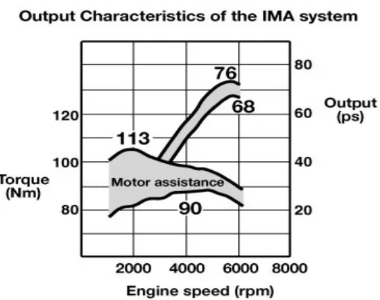
The 1.3 L engine develop 98 hp (73Kw) at 5800 rpm and 123 lb Ft (167 Nm) of torque from 1000 – 1700 rpm. the high torque at low price is made possible by electric Motor which contribute up to 13 Hp ,10 kw at 1500 rpm and 58 lb – ft ,79 Nm of torque at 1000 rpm to the power train.
[image:5.595.162.436.275.491.2]Assisting in acceleration and some study state Cursing situation low mid vehicle speed. The Motor act as Generator or, during Breaking, steady Cursing, gentle deceleration and costing in order to recharge IMA Battery. The motor also save as the Engine starter to Engine. If the car is, start at extreme cold condition IMA system disables. The car can run as petrol engine when battery is completely discharged.
[image:5.595.115.482.535.766.2]Figure No- 11 Construction of Hydrogen Engine Technology
Table 1.
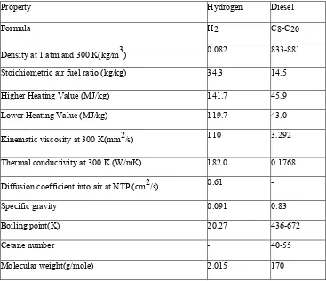
Some relevant properties of hydrogen
Property Hydrogen Diesel
Formula H2 C8-C20
Density at 1 atm and 300 K(kg/m3) 0.082 833-881 Stoichiometric air fuel ratio (kg/kg) 34.3 14.5
Higher Heating Value (MJ/kg) 141.7 45.9
Lower Heating Value (MJ/kg) 119.7 43.0
Kinematic viscosity at 300 K(mm2/s) 110 3.292 Thermal conductivity at 300 K (W/mK) 182.0 0.1768
Diffusion coefficient into air at NTP (cm2/s) 0.61 -
Specific gravity 0.091 0.83
Boiling point(K) 20.27 436-672
Cetane number - 40-55
International Journal of Emerging Technology and Advanced Engineering
Website: www.ijetae.com (ISSN 2250-2459,ISO 9001:2008 Certified Journal, Volume 5, Issue 9, September 2015)
163
3.3 The Hydrogen Internal Combustion Engine
There is not much difference between an Internal Combustion Engine runs on Petrol or Diesel and that runs on Hydrogen fuel. The main difference is that burning of fuel Technology is different in Hydrogen Engine from IC Engine & Emission level is more in IC Engine. Regarding efficiency fuel storage Hydrogen, have lower energy density that burn faster and hotter than petrol engine. Therefore, compression ratio should be increased and more amount of air can be mixed with fuel that resulting in colder running and lower emission than Petrol Engine.
As most hydrogen engine run lean air fuel ratio 30 ;1 or more as Hydrogen is gas which displace the oxygen in the cylinder supercharger is often needed to archive the required power output once the pre requisite are in place the Hydrogen Internal Combustion Engine is highly efficient up to 25%better then conventional Petrol ICE. Hydrogen storage has lower energy density means that hydrogen tank require more spark in a comparable rang for achieve strong hydrogen as liquid reduces the size but require that that the tank high Pressure up to 700 Bar or 100psi because Hydrogen gas is at normal temperature have high risk of explosion if an Hydrogen vehicle is involved in accident there are different method to slow down the release of Hydrogen from a ruptured tank and is being tested. One of these methods is to store the hydrogen from a king of Metallic metric or sponge. An iron sponge can be used as a Hydrogen storage Material. Hydrogen and rust are conventional in to pure iron, which is transported to the hydrogen consuming side. In the reverse relation oxidation rust produced librating the Hydrogen. The iron sponge storage can also be filtered or loaded with synthesis gas mixture of Hydrogen and Carbon Monoxide also librating pure hydrogen in the reverse reaction. In iron sponge, storage is early stage of development.
Many seen the main advantage of the potential to Hydrogen ICE in the potential to use in to in build momentum for a hydrogen fueling infrastructure and there by create the bridge between today’s petrol powered ICE and tomorrows hydrogen power fuel cell vehicle other advantages of Hydrogen fuel cell over ICE are:-
They can run on a blend of Hydrogen & Compressed Natural Gas.
They perform well under all weather condition. They require on warm up and have no cold start up issue even at sub zero temperature.
According to Ford Motor Hydrogen ICE can, better or more than 98% reduced Carbon Dioxide vehicle emission and performance petrol with fuel economy increase up to 50% better with aggressive Hybrid Electric Strategy.
Ford 200 Model U hydrogen ICE concept Vehicle Sport Utility Vehicles consist of 2.3L 4 cylinders supercharged intercooled Hydrogen ICE Fuel Economy 45 miles per gallon and about 300miles of range plus zero emission and 99% reduce Co2.
The Model Undrawn from no of fuel & Mazda Engine design in power fuel-efficient zero emission vehicles.
Another technology also can be developing to use chemical reaction:-
2H2+ O2 2H2O
Produce Electricity in forward reaction.
As shown in above reaction, Hydrogen & Oxygen combined to form water & Electricity is produce in this process. This concept is used to drive Vehicle with electric Motor. With help of electricity produced in above process, the research is still going on to use above technology. In Future to be used in Cars.
3.4 Production of Hydrogen:-
From water by electrolysis and thermal decomposition In the electrolysis process, electrical energy is used to break the water into the hydrogen and oxygen. However, this method has disadvantage as an energy conversion system because it requires high amount of electricity. Considerable research work is underway to develop a thermal cycle that would utilize heat to achieve the chemical splitting of water into hydrogen and oxygen. In electrolysis, high electric voltage is required while in thermal decomposition high temperature (25000C) is required. Thermo chemical method is considered most promising. It depends on complex series of interactions between the primary energy, water and some specific chemicals to produce hydrogen at temperatures substantially lower than thermal decomposition. The chemicals used are recyclable. A variety of compounds of iron, iodine, lithium, and cadmium are used for this purpose.
3.5 Utilization of hydrogen in compression ignition engines
As far as the utilization of hydrogen in compression ignition engine system is concerned, the techniques of hydrogen induction play a very important role There are basically five different techniques of hydrogen induction that were carried out in the last few decades by the researchers. They are
Carburetion technique
Continuous manifold injection (CMI) Timed manifold injection (TMI)
International Journal of Emerging Technology and Advanced Engineering
Website: www.ijetae.com (ISSN 2250-2459,ISO 9001:2008 Certified Journal, Volume 5, Issue 9, September 2015)
164
3.6 Physical Property of Hydrogen:-
The hydrogen-air flame is hotter than methane air flame and cooler than petrol at stoichiometric conditions (22070C compared to 19170C for methane and 23070C for petrol and that of diesel 23270C The lower calorific value of hydrogen on mass basis is about 2.5 times that of most hydrocarbon fuels. Yet the flame temperature for hydrogen-air mixtures is not much higher than that for hydrocarbon fuels-air mixtures. The property of wider flammability limits for hydrogen air mixtures are advantageous in diesel engines, to control the energy rates. The effects of hydrogen on flame stability are opposite to those of methane and diesel. While the tendency of flashback is more, the tendency for the blow off is less because of its high burning velocity and small penetration distance.
Hydrogen possess high rate of diffusion into air than diesel fuel. This promotes rapid mixing and enables to avoid premixing of fuel with air. Hydrogen operated engines have tendency to knock. However, this is not a serious problem if severe effective operating controls can be exercised. Various chemical properties of hydrogen and their comparison with diesel fuel are given in Table 1. While some combustion properties of hydrogen are given in Table 1
To covert hydrogen into liquid hydrogen, Critical Its critical temperature is 33Kelvin so it is to cool below this temperature.
Critical pressure is 12.96 bars; critical density is 31.02Kg /m3
Triple point temperature is -259.19 C
[image:7.595.114.481.368.684.2]At liquid phase, H2 is 99.79% in Para Hydrogen & .21% in Ortho Hydrogen.
Table 1.
Some relevant properties of hydrogen
Property Hydrogen Diesel
Formula H2 C8-C20
Density at 1 atm and 300 K(kg/m3) 0.082 833-881
Stoichiometric air fuel ratio (kg/kg) 34.3 14.5
Higher Heating Value (MJ/kg) 141.7 45.9
Lower Heating Value (MJ/kg) 119.7 43.0
Kinematic viscosity at 300 K(mm2/s) 110 3.292
Thermal conductivity at 300 K (W/mK) 182.0 0.1768
Diffusion coefficient into air at NTP (cm2/s) 0.61 -
Specific gravity 0.091 0.83
Boiling point(K) 20.27 436-672
Cetane number - 40-55
International Journal of Emerging Technology and Advanced Engineering
Website: www.ijetae.com (ISSN 2250-2459, ISO 9001:2008 Certified Journal, Volume 5, Issue 5, May 2015)
165
[image:8.595.53.280.153.302.2]3.7 PGM -FI Programmed fuel Injection System.
Figure No – 18
PGMFI: -
The proprietary programmed digital electronic fuel injection system for internal combustion engine, which inject right amount of fuel per cylinder, based on specific engine.
Fuel Injection: - It is a system of admitting fuel in to an internal combustion engine it has become primary fuel delivery system used in automotive engine having replace carburetor. The primary difference between carburetor and fuel injection is that injection is atomized the fuel through small nozzle under high pressure.
In this type of fuel injection system Air is supplies separately through Air intake manifold during suction stroke and fuel is sprayed by nozzle after completing the suction stroke and before ignition stroke. Electronic Control Module ECM does the control of quantity of fuel.
The Following Are the Component Used IN PGMFI System.
1) Injection Nozzle. 2) Fuel Pump. 3) Fuel Control Unit. 4) Engine Control Unit. 5) Wring Harness. 6) Various Sensors.
3.8 Injection Nozzle: -
It is used to inject fuel in combustion chamber with high pressure in cylinder. It has spring-loaded valve. The valve is held closed by the spring until high fuel pressure is applied through the injection pipe to the nozzle. When this happens the pressure force the valve off its seat then fuel sprays out or injected into the engine combustion chamber. The instant the pressure is relived the spring pulls the valve back on to its seat. Then fuel stops. Spraying from nozzle.
3.9 Fuel Pump: -
The fuel system uses a fuel pump to deliver fuel from tank to nozzle there are two type of fuel pump mechanical and electrical we use electrical fuel pump. The main advantage over mechanical fuel pump is fuel deliver starts as soon as ignition switch is on the pump can deliver more than the engine will require even under maximum operating condition. The engine will never be fuel a travel therefore electric fuel pump are use in many high performance heavy duty & fuel injected vehicle. There are two type of electrical pump is used 1 In line fuel pump. 2 In tank fuel pump. We use In tank fuel pump It has electric motor that drives an impeller when impeller spins it send fuel through the out let pipe to fuel injection system. An advantage of fuel pump in fuel tank is that there is pressure on fuel all the way from tank to the Engine. Therefore no vapor lock occurs. It is connect to the battery through contact in the starting motor relay. This allow the fuel pump to start delivering fuel as soon as the starting motor begins to crank engine after engine start the circuit is maintained through the oil pressure switch this arrangement shut off fuel pump whenever engine stops.
3.10 Fuel Control Unit:-
Quantity of fuel injected in to the cylinder depend on the quantity of Air entering through intake manifold and calculated by TP sensor & Map sensor this sense the pressure in intake manifold and give signal to the Electronic Control Module or ECM to calculate the quantity of Air entering in the cylinder and calculated by ECM. Now ECM gives signal to the injector to control the opening of valve of nozzle through solenoid valve.
Engine Control Unit: - It is small form of computer having microprocessor. Which takes the input from different sensors compare the signal and give signal to actuator which control various automatic system i.e. PGMFI system Ignition system, idle rpm valve timing is controlled by ECM.
3.11 Wiring Harness:-
It is used to connect different sensor battery ECM Electrical system such as headlight horn etc through wire. It should be properly covert and insulated to prevent short circuit & connected with fuse tor the safety of vehicle.
3.12 Various Sensors; -
Following are the sensor used in vehicle;-
International Journal of Emerging Technology and Advanced Engineering
Website: www.ijetae.com (ISSN 2250-2459, ISO 9001:2008 Certified Journal, Volume 5, Issue 5, May 2015)
166
3.12.1 Speedo Meter Sensor
In this type of system, a speedometer device is used for measuring and presenting speed to an operator & speed of a vehicle is such as Automobile running at that speed. A sample point is selected, at the final output of tail shaft of the transmission, where a flexible rotating Cable is driven. & other end of this cable is connected to the speedometer, which is a specially calibrated Tachometer. The response time of this Tachometer is fixed and its is calibrated numbering must take into consideration that the gear reduction from the tail shaft to the flexible cable, the final drive ratio in the differential unit, depend on the diameter of the driven tires. The Mechanism within the speedometer head will usually also drive one or more wheeled numeric counters called Odometers.
3.12.2 Manifold Absolute Pressure Sensor. MAP
In this type of sensor, the Manifold Absolute Pressure sensor is a variable resistor used to monitor the difference in pressure between the intake Manifold and outside Atmosphere pressure. This information is used by the Engine Computer to monitor engine load vacuum drops when the engine is under load or at wide-open Throttle. When the engine is under load, the computer may calculate and alter spark timing and the fuel mixture to improve performance of Engine and Emissions from vehicle.
3.12.3 Knock Sensor.
In this type of sensor, Engine an uncontrolled combustion process characterizes knock and it can damage engine or engine pars. A knock sensor prevents that, a noise sensor near the engine is placed. The Knock Sensor is a Piezo Electric Device that works when you stress it, a voltage is produced and. It is senses knock and transmits this information to the Electronic Engine &Management Control unit. This influences process control in the engine, for example timing and fuel injection until knock is eliminated.
[image:9.595.49.280.641.728.2]Knock is frequently caused by fuel that does not burn with the required minimum quality.
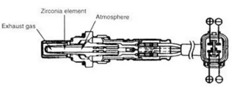
Figure NO - 19 Shows Oxygen Sensor
3.12.4 Oxygen Sensor
In this system Oxygen sensor is a chemical generator. It is constantly making a calculating and comparison between the Oxygen inside the exhaust manifold and air outside the Engine. If this comparison shows little or no Oxygen in the exhaust manifold, a voltage is generated. The output of the sensor is usually between 0 and 1.1 volts.
All spark combustion engines need the proper air fuel ratio to operate correctly. For petrol engine, the correct mixture is 14.7 parts of air to one part of fuel. When the engine has more fuel than needed, i.e. rich mixture but this condition is not applicable to Hybrid vehicle all available Oxygen is consumed in the cylinder and gasses leaving through the exhaust contain almost no Oxygen. This sends out a voltage greater than 0.45 volts. If the Engine is running Lean, all fuel is burned, and the extra Oxygen leaves the Cylinder and flows into the exhaust. In this case, the sensor voltage goes lower than 0.45 volts. Usually the output range of sensor is 0.2 to 0.7 volts.
This sensor does not begin to generate its full output until it reaches to about 600 degrees F. Prior to this time the sensor is not conductive. It is as if the circuit between the sensor and Computer is not completed. The midpoint is about 0.45 volts. This is neither rich nor lean. A fully warm O2 sensor will not spend any time at 0.45 volts. In many cars, the computer sends out a bias voltage of 0.45 through the O2 sensor wire. If the sensor is not warm, or if the circuit is not complete, the computer picks up a steady 0.45 volts. Since the computer knows this is an Illegal value, it judges the sensor to not be ready. It remains in open loop operation, and uses all sensors except the O2 to determine fuel delivery. Any time an engine is operated in open loop, it runs somewhat rich and makes more exhaust Emissions. This Translates into lost power, poor fuel Economy and air Pollution.
3.12.5 Throttle Position Sensor.
In this sensor, the TPS is a potentiometer type sensor attached to the Throttle shaft. A voltage signal is supplied to the sensor, and a variable Voltage is observed & returned to computer. This voltage increases as the throttle is opened. Moreover, signal is send to the MAP sensor output determines how much air goes into the Engine combustion chamber so the computer can respond quickly to changes, increasing or decreasing in fuel quantity is necessary according to driving condition.
3.12.6 Un Burn Exhausts Gas Sensor ( UEG)
International Journal of Emerging Technology and Advanced Engineering
Website: www.ijetae.com (ISSN 2250-2459, ISO 9001:2008 Certified Journal, Volume 5, Issue 5, May 2015)
167
It does this by reading value from multiple of sensor within the engine bay Interpreting the data using Multidimensional performance maps called look up table and adjusting the Engine actuator accordingly before ECU air fuel mixture, Ignition Timing and Idle speed where mechanically set and dynamically controlled by Mechanical and Pneumatic means.
3.13 Control of Air Fuel Ratio: -
In this type of system, the engine with fuel Injection and Engine Control Unit ECV will determine the quantity of fuel to be injected based on a number of parameter if the Throttle Position TP sensor showing that Throttle pedal is being pressed further down. The mass flow rate of air sensor will measure the amount of additional air being sucked into engine and the Electronic Lift Valve will inject fixed quantity of fuel in to the engine. If the engine tolerant temperature sensor show that engine has not warmed up to more fuel will be Injected causing Engine to run slightly rich until Engine warms up mixture control on computer controlled fuel injection work simultaneously but with a control solenoid or stepper motor in corporate in the float bowl of carbonator.
3.14 Control of Ignition Timing:-
In this type of system a spark ignition engine require a spark to initiate combustion in combustion chamber .An Electronic Control Unit can adjust the exact timing of spark called ignition timing to provide better power and economy , If Electronic Control Unit detect knock a condition which is potentially destructive to engine and determine is to be result of the ignition timing occurring too early the compression stroke delay (retread) the timing of the spark to prevent this since knock tends to occur more easily at lower RPM the program control unit may send a signal for the automatic transmission to down shift as a first attempt to activate work.
3.15 Control of Idle speed:-
Most Engine system have idle speed control built into the ECU The Engine rpm is monitored by crank position sensor CKP which play a primary role in engine timing function for fuel injection spark event and valve timing . Idle speed control by programmable throttled control stop or an idle air control steeper motor early carburetor based system used a programmable throttle stop using bidirectional Dc motor early TBI throttle control injection system used an idle air control steeper motor effective idle speed control must anticipate the engine load at idle A full authority throttle control may be used to control idle speed provide cruise control function and stop speed limitation.
3.16 Control and Variable Valve timing:-
In such engine the ECU controls the timing in the engine cycle at which the valve is open The valve are opened sooner at higher speed than at lower speed .This can be optimize the flow of air in to the cylinder increasing power and fuel economy.
3.17 Electronic Valve Control:
The first production engine of this type was invented in 2002 and introduced in 2009 by Italian automaker Fiat in Alpha Rmeo Mito. Their multi air engine uses Electronic valve Control that dramatically improve torque and H.P that reduce fuel consumption as much as 15% the valve are opened by Hydraulic pump which is operated by ECU. The valve can open several times per intake stroke based on engine load The ECU then decide how much fuel is injected. To optimize combustion.
At steady load condition, the valve open fuel is injected and valve is closed under sudden increase in throttle the valve open in the same intake stroke and a greater amount of fuel is injected. This allows the immediate acceleration for next stroke. The ECU calculates the engine load at new higher rpm and decides how to open the valve early or late wide open or half open. The optional & timing are always reached and combustion is as precise as possible. This of course is impossible with normal camshaft, which opens the valve for whole intake period and always to full lift. The elimination of cams lifter rocker & timing set reduce not only weight and bulk but also friction. A significant portion of power then an engine actually produce is used up just during the valve train. Compressing all those valve spring thousand times a minute. With electronic valve operation. It will be possible to control engine speed by regulating valve lift. At part throttle when less air and gas are needed the valve lift would not be as great, full throttle valve is achieved when pedaled is depressed sending an electric signal to the ECU, which in turn regulate the lift of each valve event.
3.18 Other Parameter That Often Map Liable are:- 3.18.1 Ignition Timing: -
Define at what point in the engine cycle the spark plug should fire per cylinder.
3.18.2 Revolution Limit: -
Define the max rpm that aloe the engine to reach after this fuel or Ignition is cut.
International Journal of Emerging Technology and Advanced Engineering
Website: www.ijetae.com (ISSN 2250-2459, ISO 9001:2008 Certified Journal, Volume 5, Issue 5, May 2015)
168
Low Fuel Pressure Modifier- Tell ECV to increase the injector fine time to consulate on loss of fuel pressure. A rare ECU is often equipped with a data logger recording all sensor for later analysis using special software in a PC This can be used to track down Engine stalls misfire or other undersigned behavior of engine. The data logger usually has capacity between .5819 megabyte (106 ).
3.19 A.C MODIFICATION TECHNOLOGY.
In this system, the Refrigerant from out let from of Evaporator is used to cool the condenser refrigerant before entering in expansion valve, which is at higher temperature than low presser line refrigerant is passed through Heat Exchanger Before entering the compressor to give extra cooling to refrigerant before passing the expansion valve. This works on the regenerative principle of cooling .And this increase the effectiveness of A.C & its efficiency.
Working of A.C:-
Heating and Air conditioning achieve a balance between comfort for passenger and fuel economy for the vehicle This unique design allows the engine Electronic control Module Unit and the Integrated Motor Assist to control the auto idle stop feature. Based upon various driving condition and Heater and Air Conditioning climate control panel selection.
The climate control is thermostatically controlled the driver simply select the desire temperature and climate control system will automatically adjust the mixture of cold 7 hot air and fan speed maintain this temperature to do this the climate control system make use of an interior temperature sensor located below the stereo control and sunlight sensor is located on the dash board at the base of the wind shield.
Interaction with idle stop Mode. In this system driver can control weather air conditioning or idle stop mode should given higher priority when the climate control system is set in full auto mode idle stop will not take place in the system whishes to run the air conditioning compressor when the climate control made is set to ECO mode. The system will function normally except that idle stop will still take place if the cabin temperature is stabilized at the set temperature possibly meaning the air conditioning compressor to stop running for the duration of auto idle stop mode. In addition to choosing between ECON and auto mode the driver can also leave the fan speed set to automatic mode or set a specific fan speed made the system will turn off the fan during idle stop mode. If a specific fan speed is set, the fan will continue to run at that speed during idle stop.
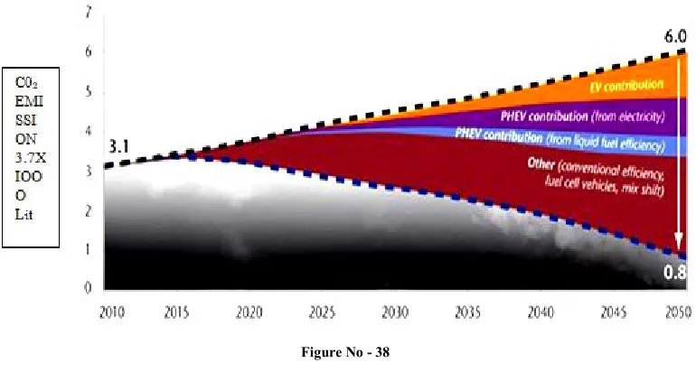
[image:11.595.107.492.460.671.2]Global Reduction Ofco2 Emission Reduction, Future Forecast
International Journal of Emerging Technology and Advanced Engineering
Website: www.ijetae.com (ISSN 2250-2459, ISO 9001:2008 Certified Journal, Volume 5, Issue 5, May 2015)
169
The above graph shows road map of reduction of CO2 shows the road map of Global reduction of CO2 Emission by year 2050 from 22200 Lit to 2960 Lit of CO2 which is presently on year 2010 is 11470 Lit of CO2 emitted Globally from Vehicle so there is need of government & Industries to work together & reduce taxes on HEV / PHEV Vehicle and give extra price relaxations on above vehicle or for incentive scheme for government employee to for the purchase of above vehicle & promote the sales of vehicle from above graph it is analyze that in year 2050 there is high increase in emission of CO2 so government have to keep check on above problem
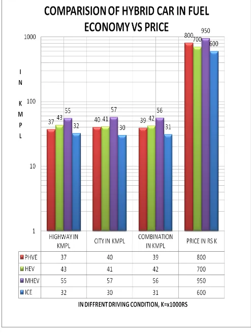
[image:12.595.47.294.323.653.2]Comparison Of Plug In Hybrid Passenger Car Hybrid Electrical Car &Multi Hybrid Passenger Car With Fuel Economy In Different Driving Condition
Figure No - 1 BAR CHART
Description of above Chart
The above sample of data is taken on the passenger car of 1.5L capacity on Curb weight of 4stroke 4 Cylinder petrol Engine Curb means weight of car without Accessories including weight of fuel & oil
At constant speed of driving of 60 KMPH on plain & Empty road when storage battery of 210V 50Kw is fully charged & Vehicle is tested on idle condition from above chart data we have analyzed that Avg fuel consumption of conventional IC Engine is high and vehicle with Multi Hybrid Average fuel consumption is lowest because fuel used in this engine is Hydrogen from other three engine tested but price of the Multi hybrid vehicle is higher than other three vehicle due to additional cost of battery roof solar panel & hydrogen storage cylinder since Hydrogen is lighter and less denser than liquid petrol that is why it give it gives 35% more fuel economy than petrol engine. & use of solar panel give extra fuel economy of 2% to 5% depend on the position of sun & outer forecast condition outside the Vehicle. Cost Estimation and
Engine specification is given below. & component cost is taken in Rs
Comparison Of Ic Engine, Multi Hybrid Vehicle, Plug In Hybrid, And Hybrid Electrical Vehicle. With Emission Of Co2 / Year Vs Amount Of Fuel Used In Liter / Year &
Cost Of Fuel Used In One Year In Rupees.
International Journal of Emerging Technology and Advanced Engineering
Website: www.ijetae.com (ISSN 2250-2459, ISO 9001:2008 Certified Journal, Volume 5, Issue 5, May 2015)
170
Sample of data is taken from above engine specification for Multi Hybrid car & Hybrid car of different combination of technology the data used below in Bar chart is taken from US Agency.
Further It is assumed that Vehicle is running 17000 Km / year & All the consumption of fuel, CO2 Emission from vehicle is calculated for One year of average running of 4S 1.5L engine capacity & petrol as fuel for ICE, PHEV, HEV & Hydrogen gas as fuel for Multi hybrid Vehicle & further cost of petrol is calculated as @ 74Rs / Lit & cost of Hydrogen Gas as @ 64Rs / kg & Avg of fuel consumption is taken as combined Avg of High way & City Condition.
Calculation For ICE PHEV HEV & MHEV
Calculation for IC Engine using petrol as Fuel of CVT Transmission Battery 12V Avg running for one year is 17000Km /year at 60Km / hr Avg speed. & fuel economy of 31KMPL. & CO2 Emission for ICE is 218gm / km at idle condition
So therefore, quantity of CO2 Emitted in one year is 218 X 17000 = 3706000 gm or 3706Kg in one year without catalytic convertor
Total fuel consumed & cost of fuel in one year is 17000 / 31 = 548.38 Lit X @74Rs / L = 40580Rs.
PHEV calculation vehicle used is of same capacity as mention above & same condition.
Engine fuel Economy is taken as 39KMPL & CO2 Emitted is 169gm / km
Therefore, Quantity of CO2 Emitted in one year is 17000 X 169 = 2873000gm in one year or 2873kg. Without catalytic convertor
Total fuel consumed & cost of fuel in one year 17000 / 39 = 435.89Lit X @ 74Rs / L = 32256Rs and 5000Rs for Electrical charging of battery by power point total expenditure on fuel is equal to 32256+5000 = 37256 Rs
HEV Calculation Vehicle fuel Economy is taken as 42KMPL and CO2 Emission as 120gm / kg .With same engine capacity & fuel and same above condition.
Therefore, Quantity of CO2 Emitted in one year is 17000 X 120 = 2040000gm in one year or 2040kg of CO2
Total fuel consumed & cost of fuel in one year 17000 /42 = 404.46Lit X @ 74Rs / L = 29552Rs and 6000Rs for Electrical charging of battery by power point total expenditure on fuel is equal to 29552+6000 = 35925 Rs
MHEV Calculation Vehicle fuel Economy is taken as 56KMPL and CO2 Emission as ZERO gm / kg .With same engine capacity & fuel Used is Hydrogen Gas and same above condition. But when vehicle is used in emergency condition when Hydrogen gas is not available it is consider as it will Emits 2kg of CO2 in one year
Therefore, Quantity of CO2 Emitted in one year is 17000 X 0 .1176 = 2000gm in one year or 2kg of CO2
Total fuel consumed & cost of fuel in one year 17000 /56 = 303.57Lit X @ 74Rs / L = 18821.23Rs and 7500000Rs for Electrical charging of battery by power point total expenditure on fuel is equal to 18821+75000 = 29964.28 Rs
From above calculation we have concluded that development of Multi Hybrid Vehicle is profitable & environmental friendly project to developed in India which not only save money & environment from Global warming but also save fuel & money for customer due to its high fuel efficiency but it will work at Zero emission of CO2 level if it is manufacture in in India & Export to foreign countries like USA Europe etc it will be great boost up for Indian Economy. It is also help to solve unemployment problem of our country to some Extend
From the data given below is compared & analyzed to be concluded that the different type of Vehicle used for the analysis of total fuel consumption in one year & emission of vehicle in one year
We concluded that ICE Vehicle emission of CO2 is highest than other three vehicle used & uses larger amount of fuel for running same distance & Multi Hybrid vehicle is highest fuel Economy & Zero Emission using Hydrogen as fuel but the cost of production of Multi Hybrid is highest than other three type of vehicle used for analysis. Because it includes additional cost of roof solar panel TPV &battery, use for storage of energy is Li ion rechargeable battery. & fuel storage cylinder of Hydrogen gas.
IV. CONCLUSIONS
1. With the use of above, Technology We can develop the car of next generation called Multi Hybrid Car. Because In next 150 year the fuel we are using get, exhausted and available fuel is Hydrogen fuel cell produced by water, solar energy, & CNG gas. Etc. Therefore, we need to develop Technology, which can utilize above available resources such as Hydrogen or CNG as conventional fuel & Solar as second source of Energy plus PHEV for Hybrid car to Next generation .or combination of all above Technology Explain in thesis.
International Journal of Emerging Technology and Advanced Engineering
Website: www.ijetae.com (ISSN 2250-2459, ISO 9001:2008 Certified Journal, Volume 5, Issue 5, May 2015)
171
3. From Heat Balance sheet It is found that Combustion of Hydrogen Require 43.3% more Oxygen then Petrol fuel so Extra oxygen is provided for When Hydrogen is used as fuel for combustion It is mixed with oxygen before entering to combustion chamber in mixing chamber provided before with Injection system. or quantity of 1gm Hydrogen is reduced to 44% minimize quantity by 0.56gm in one sec & one third of 0.56 is equal to 0.183gm is supplied in one sec. or use of Hydrogen fuel Cell is recommended which produce Hydrogen & Oxygen for Combustion. This will reduce further fuel consumption to 44% for Hydrogen fuel. It is analyzed that use of TPV increase it Efficiency by 42% from 25%
REFERENCES
[1] "The World's First Hybrid Train Officially Enters Commercial Service" In ENN.com. On 24. 102007 Retrieved in 13. -01-2012
[2] "Hybrid Electric HMMWV "in.GlobalSecurity.Org. Retrieved on
200811-17.
[3] Jolly, David In March 1, 2013 "Compressing Gas for a Cheaper,
Simpler Hybrid". In The New York Times Retrieved March on 2,
2013.
[4] "Honda IMA technology". In Honda Motor Retrieved on 2009-05-01
[5] California Cars Initiative. "All about Plug-In Hybrids
(PHEVs)"International Humanities Center on 2013-05-01. [6] "Prius PHEV". Electric Auto Association – Plug in Hybrid
Electric Vehicle on 2012-01-14
[7] "EPA and Chrysler to Take Latest Hybrid Technology from Lab
to Street Partnership to adapt fuel efficient technology" Press release Yosemite.epa.gov.on 2011-01-19.
[8] An amazin 75 – MPG hybrid electric car Motherearthnews.com.
& Retrieved on 2012-04-18
[9] Alliance Bernstein "The Emergence of Hybrid Vehicles: Ending Oil's Stranglehold on Transportation and the Economy," on June 2006. Calcars.org
[10] Shah, Saurin D In. 2009. "2 Electrification of Transport and Oil
Displacement". In David. Plug-In Electrical Vehicles: What Role
for Washington. Brookings Institution Sandalow, ISBN 978-0-8157-0305-1. Retrieved on 2011-08-11
[11] Environmental Activities. Retrieved December 01, 2009, from
Lithium-ion battery for Hybrid Electric Vehicles: Hitachi.com
[12] Anderman, M. . . Gap Analysis for Li-ion Batteries for
Automotive Applications Advanced Automotive Batteries Conference 2007 Long Beach, California. Bureau of the Census. 2008. American Housing Survey.
[13] Kalhammer, F.R., B. Kopf, D. Swan, V. Roan, and M. Walsh.
2007. Status and Prospects for Zero Emissions Vehicle Technology. Sacramento, State of California Air Resources
[14] Morrow, K., D. Karner, and J. Frankfort. 2008. Plug-in Hybrid Electric Vehicle Charging Infrastructure Review. INL / EXT-08-15058 Battelle Energy Alliance November
[15] PNNL Pacific Northwest National Laboratory in 2007. Impacts
Assessment of Plug-In Hybrid Vehicles on Electric Utilities and Regional U.S. Power Grids.
[16] Plotkin, S., and Margaret Singh, Argonne National Laboratory in
2009. Multi-Path Transportation Futures Study
BIBLIOGRAPHY
Ninth edition automotive mechanic WILLIAM H CROUSE DONALD AL ANGLING by TMH 1986 Edition
Modern electric hybrid and electric fuel cell vehicle ; fundamental theory and design second edition - Mehreds Eghsami 2009 edition ISBN -10:1420053981 CRC Press Taylor& Francis groups.
Build your own plug in hybrid electric vehicle by Lietman by Mc hill professional edition 2009 ISBN -10:184002564
Hybrid vehicle and future of personal transportation by Allen fuhs 2008 edition by CRC press ISBN-9781420073342
Fuel cells modeling control and application by Bei Gou woonkintu bill drung by CRC Press ISBN 9781420071610
Energy conservation by D.yogi go swami Frank Erith CRC Press ISBN - 9781420044317 ZOOS Edition Work shop Manual Honda civic 2005 from Abhikaran Honda .k Road Bhopal.
Work shop Manual Super Cars Ltd J.k Road Bhopal.
BIOGRAPHY
SHYAM SUNDER Completed his B.E Degree in Mechanical Engineering Branch from JTM COE FAIZPUR MAHARASHTRA India in 2000 and pursuing M. Tech in Thermal Engineering RGPV Bhopal M.P India. Shyam Sunder also completed MBA in Operational Management from Sikkim Manipal University