Secret Image Sharing for General Access Structures
using Random Grids
Sachin Kumar
Department of Mathematics Indian Institute of Technology Delhi Hauz Khas, New Delhi - 110016, IndiaR. K. Sharma
Department of Mathematics Indian Institute of Technology Delhi Hauz Khas, New Delhi - 110016, IndiaABSTRACT
This paper presents a visual secret sharing (VSS) scheme for general access structures by using random grids. Com-pared to the existing VSS schemes for general access struc-tures, the proposed scheme generates the shares of same size as that of the original secret image and does not require any codebook prior to encryption process. With these advan-tages, the proposed scheme broadens the potential applicabil-ity of random-grid based VSS. We prove that the proposed scheme gives the strong access structure. Formal proofs, secu-rity analysis and experimental results are given to demonstrate both the feasibility and the correctness of the proposed scheme.
General Terms:
Cryptography, Information Security
Keywords:
Visual secret sharing, Visual cryptography, Random grids, General access structure, Image encryption
1. INTRODUCTION
Shamir [12] and Blakley [3] independently proposed (k, n )-threshold secret sharing (SS) scheme in which a secret is shared amongn participants such that the secret can be obtained by at leastk(≤n)participants together, but anyk−1or fewer partici-pants cannot obtain any secret information. The SS schemes [3, 12] reconstruct the secret accurately by using complex computation. To share a visual secret information, several visual secret sharing (VSS) schemes [4–9, 11, 13, 14, 16] are developed involving com-plex, little or no computation in the decryption phase.
In 1995, Naor and Shamir [11] proposed a new technique known as Visual Cryptography (VC), which shares a visual information and removes the problem of computation involved in the decryp-tion phase. Naor and Shamir’s scheme is a(k, n)-threshold scheme, which encrypts a black and white secret image intonmeaningless shares such that knowledge of less thank shares reveals nothing about the secret image. However, the secret image can be recon-structed by xeroxing at leastk(≤n)shares on transparencies and stacking these transparencies together. The reconstruction is per-formed by human visual system without any computation. A VC scheme for an access structure splits the secret image into a set of
shares such that certain qualified set of participants can visually re-cover the secret image, but other forbidden set of participants have no information about the secret image. The different construction techniques of VC scheme for general access structures, where an access structure is a specification of all qualified and forbidden sets of participants, were studied in [1, 2]. These schemes generate the shares of the size larger than that of the secret and require collec-tions of basis matrices (codebook) prior to encryption process. In 1987, Kafri and Keren [6] proposed a random-grid based(2,2) VSS technique in which a binary secret image is encrypted into two cipher grids without any pixel expansion and codebook require-ment. The decryption is same as in traditional VC. Shyu [13] ex-tended Kafri and Keren’s scheme to(n, n)scheme for anyn(≥2). Chen [4] also proposed(2, n)and(n, n)VSS schemes based on random grids. Further, Chen and Tsao [5] proposed a random-grid based(k, n)-threshold VSS scheme, which is limited to threshold access structure and cannot be used for general access structures. Wu and Sun [16] developed a VSS scheme for general access struc-tures. In their scheme original basis matrices, generated by the con-ventional VC scheme for general access structures [2], are modified to generate the shares. However, Wu and Sun’s scheme has no pixel expansion but requires to generate basis matrices prior to encryp-tion process. Recently, Shyu [14] proposed another VSS technique for general access structures without any pixel expansion and code-book requirement. They gave two construction techniques, where one uses the basis and other uses the collection of maximal forbid-den sets to generate a set of visual cryptograms of random grids. For a given access structure, both the construction techniques can yield the reconstructed images of different quality.
In this paper, a random-grid based VSS scheme for general access structures is designed having the following merits.
1. No pixel expansion - The size of each share is same as that of the original image. It makes the storage and distribution of shares more efficient.
2. No codebook requirement - The proposed scheme does not re-quire the collections of basis matrices for generating shares. 3. Generalized - The proposed scheme generalizes the existing
random-grid based VSS schemes to general access structures. 4. Wide image format - The proposed scheme can be used to
en-crypt binary as well as color images.
and color images. The security and performance analysis of the proposed scheme are discussed in Section 4. Section 5 presents the experimental results and comparison with related work. Finally, the paper is concluded in Section 6.
2. PRELIMINARIES
This section presents the results from VC schemes for general ac-cess structures and discusses traditional random-grid based VSS.
2.1 Review of VC schemes for general access structures
LetP ={1,2, ..., n}be a set ofnparticipants, and2P
denote the set of all subsets ofP. LetΓQual ⊆ 2P andΓF orb ⊆ 2P, where ΓQual∩ΓF orb =∅. The members ofΓQualare referred as qual-ified sets, while the members ofΓF orb are referred as forbidden sets. The pair(ΓQual,ΓF orb)is known as the access structure. We defineΓ0as a set consisting of the minimal qualified sets, i.e.,
Γ0={Q∈ΓQual:Q06∈ΓQual,∀Q0⊂Q}. A monotone increas-ing (respectively monotone decreasincreas-ing) access structureΓonPis a subsetΓ⊆2P\∅(Γ⊆2P)such that ifQ∈ΓandQ⊆Q0⊆ P (respectivelyQ0⊆Q⊆ P), thenQ0∈Γ. IfΓ
Qualis monotone in-creasing,ΓF orbis monotone decreasing, andΓQual∪ΓF orb= 2P then the access structure is called strong access structure andΓ0is
called the basis of the access structure,.
Ateniese et al. [2] were the first to consider VC-based VSS for gen-eral access structures. They proposed two constructions for binary images. The first construction uses the cumulative array method to generate shares, while in the second construction smaller schemes are used as building blocks in construction of larger schemes. In [2], both constructions give strong access structure and obtain the pixel expansion as presented by the following results.
Result 1:Let(ΓQual,ΓF orb)be a strong access structure. Any set
F ∈ ΓF orbis said to be maximal forbidden ifF ∪ {p} ∈ΓQual for all p ∈ P\F. Let ZM denote the collection of the maxi-mal forbidden sets inΓF orb. Then, for the given access structure, there exists a VC scheme having pixel expansion equals to2|ZM|−1.
Result 2: Let (ΓQual,ΓF orb) be a strong access structure with the basisΓ0. Then, for the given access structure, there exists
a VC scheme having pixel expansion equals toP
X∈Γ02
|X|−1.
Adhikari et al. [1] proposed another black and white VC for strong access structures, where basis matrices are constructed by using the fact that the collection of all solutions of a system of linear homogeneous equations over the binary field forms a vector space over the base field.
2.2 Review of traditional random-grid based VSS A random grid is defined as a transparency comprising a two-dimensional array of pixels, where each pixel is either transparent (0) or opaque (1), chosen randomly similar to a coin-flip procedure. Kafri and Keren [6] proposed three algorithms to encrypt a binary image into two cipher grids, which are regarded as Algorithms 1-3.
Input: Binary secret imageAof the sizeh×w. Output: Cipher gridsR1andR2of the sizeh×w.
Algorithm 1
Step 1.1 GenerateR1 randomly, i.e., R1[i, j] = random(0,1),
where1≤i≤hand1≤j≤w
Step 1.2 GenerateR2byR1andAas follows
for (each pixelA[i, j],1≤i≤hand1≤j≤w) {
if (A[i, j] = 0)R2[i, j] =R1[i, j]
elseR2[i, j] =R1[i, j]
}
Step 1.3 output (R1, R2)
Algorithm 2
Step 2.1 Generate R1 randomly, i.e., R1[i, j] =random(0,1),
where1≤i≤hand1≤j≤w
Step 2.2 GenerateR2byR1andAas follows
for (each pixelA[i, j],1≤i≤hand1≤j≤w) {
if (A[i, j] = 0)R2[i, j] =R1[i, j]
elseR2[i, j] =random(0,1)
}
Step 2.3 output (R1, R2)
Algorithm 3
Step 3.1 Generate R1 randomly, i.e., R1[i, j] =random(0,1),
where1≤i≤hand1≤j≤w
Step 3.2 GenerateR2byR1andAas follows
for (each pixelA[i, j],1≤i≤hand1≤j≤w) {
if (A[i, j]=0)R2[i, j]=random(0,1)
elseR2[i, j] =R1[i, j]
}
Step 3.3 output (R1, R2)
random(0,1)is a function that returns a value (0 or 1) randomly.
Ris defined as an inverse grid of a binary gridRof the sizeh×w
obtained by bitwise complementing ofR, i.e.,R[i, j] = 1−R[i, j] for1 ≤ i≤ hand1≤ j ≤ w. The cipher gridsR1 andR2do
not reveal any secret information. However, the image obtained by stackingR1andR2visually reveals the secret image.
3. THE PROPOSED SCHEME
This section presents the proposed scheme for general access struc-tures based on random grids. The proposed scheme encrypts a se-cret image inton(≥ 2)cipher grids such that each cipher grid is meaningless, and stacking result of the cipher grids corresponding to participants of any forbidden set reveals no secret information. However, the secret image can be recognized visually by stacking the cipher grids corresponding to participants of any qualified set.
3.1 Scheme for binary images
Some notations are given before presenting the proposed scheme. Let (ΓQual,ΓF orb) be a strong access structure defined on a set of n participants P = {1,2, ..., n} with the basis Γ0.
Let |Γ0| = N and Γ0 contains the subsets of P of different
cardinalities m1, m2, ..., mr, where m1 < m2 < ... < mr and mj ∈ {2,3, ..., n}for1 ≤ j ≤ r. Letnj (1 ≤ j ≤ r) denote the number of subsets of cardinality mj in Γ0, where nj ∈ {1,2, ..., mn
j
}andn1+n2+...+nr = N. We define Γ0 = {Bm11, ..., B
n1 m1, B
1
m2, ..., B n2 m2, ..., B
1
mr, ..., B
nr
mr}, where Bt
mk denotes t
th subset of cardinality m
k, 1 ≤ t ≤ nk and 1 ≤ k ≤ r. Let Bt
mk be the set of participants pt
1, pt2, ..., ptmk∈ {1,2, ..., n}, i.e.,B
t mk={p
t
procedure for sharing a secret image intoncipher grids for any general access structure is given in Algorithm 4. Here,⊕denotes the Boolean exclusive OR operation.
Input: Binary secret imageAof the sizeh×wand a strong access structure(ΓQual,ΓF orb)with the basisΓ0.
Output: Cipher gridsR1, R2, ..., Rnof the sizeh×w. Algorithm 4
Step 4.1 Select a pixelA[i, j]∈Aand encrypt it intonrandom valuesR1[i, j], R2[i, j], ..., Rn[i, j]by following Steps 4.2 to 4.6
Step 4.2 Select randomly one set from the basisΓ0. Let us assume
that the selected set isBt
mk, wheret∈ {1,2, ..., nk}andk∈
{1,2, ..., r}
Step 4.3 For the selected pixel A[i, j] generate binary values
a1, a2, ..., amk by using the traditional random-grid based
VSS as follows
Step 4.3.1 Generate a1, a2, ..., amk−1 independently by the
functionrandom(0,1)
Step 4.3.2 Select one algorithm from Algorithms 1-3 and gen-erateamkfroma1, a2, ..., amk−1as follows
b1=a1
for(2≤l≤mk−1) {
bl=bl−1⊕al }
Case 1: Algorithm 1 is selected if(A[i, j] = 0)amk=bmk−1
elseamk=bmk−1
Case 2: Algorithm 2 is selected if(A[i, j] = 0)amk=bmk−1
elseamk=random(0,1)
Case 3: Algorithm 3 is selected
if(A[i, j] = 0)amk=random(0,1)
elseamk=bmk−1
Step 4.4 Generate the binary values amk+1, amk+2, ..., an
in-dependently by the function random(0,1), i.e., au =
random(0,1)∀u∈ {mk+1, mk+2, ..., n}
Step 4.5 Assigna1, a2, ..., amkat the location[i, j]of the random grids corresponding to the participants of selected setBt
mk,
i.e.,
Rpt
1[i, j] =a1 Rpt
2[i, j] =a2
.. . .. .
Rpt
mk[i, j] =amk
Step 4.6 Assign amk+1, amk+2, ..., an randomly at the location
[i, j]of the remaining(n−mk)random grids
Step 4.7 Repeat Step 4.1 until all the pixelsA[i, j]of the secret imageAare encrypted
Step 4.8 output(R1, R2, ..., Rn)
3.2 Scheme for color images
The proposed scheme can be easily extended to color images by adopting a similar procedure as discussed in [4, 5]. A color model, which is either additive (RGB) or subtractive (CMY), is employed to decompose the color image into three channels. The procedure
to encrypt a color secret imageBfor general access structures is given as follows:
Step 5.1 Decompose the color secret image B into three color components Cyan, Magenta and Yellow (CMY), i.e.,BC, BM andBY
Step 5.2 By using error diffusion halftone techniques [10, 15], transform the color components BC, BM and BY into halftone images, i.e.,HBC, HBMandHBY
Step 5.3 Generatencipher grids for each of halftone color compo-nentsHBC, HBM andHBY by using the proposed scheme for binary images, i.e.,RC
i, RMi andRYi where1≤i≤n Step 5.4 The color components of the cipher gridsRC
i , RMi and
RY
i are combined to form eight color cipher gridRi, i.e.,Ri= (RC
i, R M i , R
Y
i )where1≤i≤n Step 5.5 output(R1, R2, ..., Rn)
4. PERFORMANCE ANALYSIS
The performance of the proposed scheme is measured in terms of the security of the original image and the visual quality of the re-constructed image.
DEFINITION 1. For a certain pixel r in a binary image R
of the size h×w, the light transmission of r (t(r))is defined as the probability of r to be transparent (i.e., P rob(r = 0)). Thus, the light transmission of a transparent(respectively opaque) pixel r ∈ R is t(r) = 1 (respectively t(r) = 0). Addition-ally, the average light transmission of R is defined asT(R) =
1
h×w
Ph i=1
Pw
j=1t(R[i, j]).
In random-grid based VSS, the visual quality of the reconstructed image is measured by the contrast [13], which is defined as follows.
DEFINITION 2. The contrast of the imageSreconstructed for the binary image A is defined as α = T(S[A1+(0)])T(S−[TA(1)])(S[A(1)]).
A(0) (respectively A(1)) denotes the area of all transparent (respectively opaque) pixels inA, withA = A(0)∪A(1)and
A(0)∩A(1) =∅.S[A(0)] (respectivelyS[A(1)])denotes the area of all pixels inScorresponding toA(0) (respectivelyA(1)).
DEFINITION 3. For the contrastα >0, the reconstructed im-ageSvisually reveals the original imageA. Precisely,α >0 im-pliesT(S[A(0)])> T(S[A(1)])andSis visually recognizable as
A. Forα= 0 (i.e.T(S[A(0)]) =T(S[A(1)])),Sis meaningless and reveals no information aboutA.
IfRis a random grid, then forr ∈ R, the probability ofrto be transparent (0) is equal to the probability ofr to be opaque (1), i.e.,P rob(r = 0) = P rob(r = 1) = 1
2. Since the number of
transparent pixels is probabilistically equal to that of opaque pixels inR, we haveT(R) = 12. Let⊗denote Boolean OR operation, which simulates the human visual system.
LEMMA 4. Ifr1, r2, ..., rnarenrandom pixels generated in-dependently by the functionrandom(0,1), thenP rob(r1⊗r2⊗ ...⊗rn= 0) =21n.
PROOF. We prove by mathematical induction on n. We have
P rob(r1⊗r2= 0) =P rob(r1= 0)×P rob(r2= 0) = 12× 1 2 = 1
22, i.e., the result is true forn= 2.
Assume that the result holds forn−1, i.e.,P rob(r1⊗...⊗rn−1=
0) = 1
2n−1. We have to prove that it holds fornalso. We know
thatP rob(r1⊗...⊗rn−1⊗rn= 0) =P rob(r1⊗...⊗rn−1=
0)×P rob(rn= 0) = 2n1−1 ×
1 2 =
LEMMA 5. Ifr1, r2, ..., rnarenrandom pixels generated in-dependently by the functionrandom(0,1), thenP rob(r1⊕r2⊕ ...⊕rn= 0) = 12.
PROOF. We prove by mathematical induction onn. We have
P rob(r1 ⊕ r2 = 0) = P rob(r1 = 0) ×P rob(r2 = 0) + P rob(r1 = 1)×P rob(r2 = 1) = (12 × 12) + (12 × 12) = 12,
i.e., the result is true forn= 2.
Assume that the result holds forn−1, i.e.,P rob(r1⊕...⊕rn−1=
0) = 1
2. We have to prove that it holds fornalso. We know that P rob(r1 ⊕...⊕rn−1⊕rn = 0) = P rob(r1⊕...⊕rn−1 =
0)×P rob(rn= 0) +P rob(r1⊕...⊕rn−1= 1)×P rob(rn= 1) = (1
2 × 1 2) + (
1 2 ×
1 2) =
1 2.
THEOREM 6. In the proposed random-grid based VSS scheme for general access structures, each cipher grid is meaningless and reveals no information about the secret imageA.
PROOF. In the proposed scheme, each pixelA[i, j]∈Ais en-crypted corresponding to a minimal qualified set randomly selected from the basis Γ0. Let A[i, j] be encrypted corresponding to a
minimal qualified set of cardinalitymk, wherek ∈ {1,2, ..., r}. Therefore, the pixel values at location [i, j]of the cipher grids
R1, R2, ..., Rn (i.e., R1[i, j], R2[i, j], ..., Rn[i, j]) are selected among the binary values a1, a2, ..., amk−1, amk, amk+1, ..., an
that are generated by Steps 4.3 to 4.4 of the proposed scheme. Since the binary valuesa1, a2, ..., amk−1, amk+1, ..., an are generated
independently by the functionrandom(0,1),P rob(al= 0) = 12
for1≤l≤mk−1andmk+1≤l≤n.
From Step 4.3.2 of the proposed scheme, we havebmk−1=a1⊕ a2⊕...⊕amk−1. By Lemma 5, we obtain
P rob(bmk−1= 0) = 1 2.
Asamk depends on the algorithm selected from Algorithms 1-3,
three cases are considered as follows.
In Algorithm 1, forA[i, j] = 0,amk=bmk−1, i.e,P rob(amk=
0) = P rob(bmk−1 = 0) = 1
2. While forA[i, j] = 1,amk = bmk−1, i.e.,P rob(amk = 0) = 1−P rob(bmk−1 = 0) =
1 2.
Therefore,P rob(amk= 0) = 1 2.
In Algorithm 2, forA[i, j] = 0,amk=bmk−1, i.e.,P rob(amk=
0) = P rob(bmk−1 = 0) = 12. While for A[i, j] = 1, amk = random(0,1), i.e., P rob(amk = 0) =
1
2. Therefore, P rob(amk= 0) =
1 2.
In Algorithm 3, for A[i, j] = 0, amk = random(0,1), i.e., P rob(amk = 0) =
1
2. While forA[i, j] = 1, amk = bmk−1,
i.e.,P rob(amk = 0) = 1−P rob(bmk−1 = 0) = 1
2. Therefore, P rob(amk= 0) =
1 2.
Precisely, no matter ifA[i, j] = 0or1, we obtainP rob(Rl[i, j] = 0) =1
2, i.e.,t(Rl[i, j]) = 12for1≤l≤n. Therefore,
T(Rl[A(0)]) =T(Rl[A(1)]) = 12,
where1≤l≤n. Hence, each cipher grid is meaningless and does not reveal any information about the secret imageA.
THEOREM 7. In the proposed random-grid based VSS scheme for general access structures, stacking the cipher grids correspond-ing to the participants of any forbidden set cannot reveal the secret imageA.
PROOF. LetF = {p1, p2, . . . , ps}be any forbidden set and
Sdenote the stacking result of the cipher grids corresponding to the participants ofF, i.e.,S[i, j] =Rp1[i, j]⊗Rp2[i, j]⊗. . .⊗ Rps[i, j], where1≤i≤hand1≤j≤w. We define
CF ={Q∈Γ0 : F⊂Q}.
In the proposed scheme, each pixelA[i, j]∈Ais encrypted corre-sponding to a minimal qualified set, which is selected from the ba-sisΓ0randomly. LetA[i, j]be encrypted corresponding to a
mini-mal qualified setQ1∈Γ0. Two cases are considered, where Case
1 is forQ16∈CForCF =∅, and Case 2 is forQ1∈CF. Case 1: In this case, for A[i, j] = 0 or 1, the pixels
Rp1[i, j], Rp2[i, j], . . . , Rps[i, j]are generated independently as
random values. By Lemma 4, no matter ifA[i, j] = 0or 1, we obtainP rob(S[i, j] = 0) = 1
2s, i.e.,t(S[i, j]) =21s. Therefore, T(S[A(0)]) =T(S[A(1)]) = 1
2s. (1)
Case 2: Let|Q1|=mkfor somek∈ {1,2, . . . , r}. SinceF⊂Q1
andQ1 ∈Γ0, the pixel values at any location[i, j]of the cipher
grids corresponding to the participants ofF will be assigned from the set{a1, a2, . . . , amk}generated as in Step 4.3 of the proposed
scheme. IfD = {Rp1[i, j], Rp2[i, j], . . . , Rps[i, j]}, thenD ⊂
{a1, a2, . . . , amk}. Consideringamk as the last value generated
based on selection from Algorithms 1-3, we have eitheramk 6∈D
oramk∈D.
If amk 6∈ D, thenD ⊆ {a1, a2, . . . , amk−1}. We know that a1, a2, . . . , amk−1 are generated independently by the function random(0,1). By using Lemma 4, forA[i, j] = 0or1, we ob-tainP rob(S[i, j] = 0) = 1
2s, i.e.,t(S[i, j]) =21s. Therefore, T(S[A(0)]) =T(S[A(1)]) = 1
2s. (2)
If amk ∈ D, then consider Rpu[i, j] = amk for
some u ∈ {1,2, ..., s}. If D1 = D \ {Rpu[i, j]} =
{Ry1[i, j], . . . , Rys−1[i, j]}, then each pixel Ryv[i, j] ∈ D1
is generated independently by the function random(0,1), i.e.,
P rob(Ryv[i, j] = 0) = 1
2 for1 ≤ v ≤ s−1. By Lemma 4,
we obtain
P rob(Ry1[i, j]⊗. . .⊗Rys−1[i, j] = 0) =
1 2s−1.
We know thatRy1[i, j]⊗. . .⊗Rys−1[i, j]will be transparent (0)
only if
Ry1[i, j] =. . . .=Rys−1[i, j] = 0.
If Ryv[i, j] = 0 (1 ≤ v ≤ s − 1), then bmk−1 = Rz1[i, j]⊕. . .⊕Rzmk−s[i, j], where{Rz1[i, j], . . . , Rzmk−s[i, j]}
={a1, a2, . . . , amk−1} \D1. By using Lemma 5, we obtain
P rob(bmk−1= 0) = 1 2.
We have P rob(S[i, j] = 0) = P rob(Ry1[i, j] ⊗ . . . ⊗ Rys−1[i, j] = 0)×P rob(Rpu[i, j] = 0). Therefore,
P rob(S[i, j] = 0) = 1
2s−1 ×P rob(Rpu[i, j] = 0). (3)
The pixelRpu[i, j](= amk) depends uponbmk−1 and the
algo-rithm selected from Algoalgo-rithms 1-3.
In Algorithm 1, forA[i, j] = 0, we haveRpu[i, j] =bmk−1, i.e., P rob(Rpu[i, j] = 0) =P rob(bmk−1 = 0) =
1
2. From (3), we
obtainP rob(S[i, j] = 0) = 1 2s−1×
1 2 =
1
2s, i.e.,t(S[i, j]) =21s.
Therefore,
T(S[A(0)]) = 1
2s. (4)
In addition, for A[i, j] = 1, we have Rpu[i, j] = bmk−1, i.e., P rob(Rpu[i, j] = 0) = 1−P rob(bmk−1= 0) =
1
2. From (3), we
obtainP rob(S[i, j] = 0) = 1 2s−1×
1 2 =
1
2s, i.e.,t(S[i, j]) = 1 2s.
Therefore,
T(S[A(1)]) = 1
From (4) and (5), we have
T(S[A(0)]) =T(S[A(1)]) = 1
2s. (6)
In Algorithm 2, forA[i, j] = 0, we haveRpu[i, j] =bmk−1. We
obtain
T(S[A(0)]) = 21s. (7)
In addition, forA[i, j] = 1, we haveRpu[i, j] =random(0,1),
i.e., P rob(Rpu[i, j] = 0) = 1
2. From (3), we obtain P rob(S[i, j] = 0) = 1
2s−1 ×
1 2 =
1
2s, i.e.,t(S[i, j]) = 1 2s.
There-fore,
T(S[A(1)]) = 1
2s. (8)
From (7) and (8), we have
T(S[A(0)]) =T(S[A(1)]) = 1
2s. (9)
In Algorithm 3, for A[i, j] = 0, we have Rpu[i, j] = random(0,1), i.e.,P rob(Rpu[i, j] = 0) =
1
2. From (3), we
ob-tainP rob(S[i, j] = 0) = 1 2s−1 ×
1 2 =
1
2s, i.e.,t(S[i, j]) = 21s.
Therefore,
T(S[A(0)]) = 1
2s. (10)
In addition, forA[i, j] = 1, we haveRpu[i, j] =bmk−1. We obtain
T(S[A(1)]) = 21s. (11)
From (10) and (11), we have
T(S[A(0)]) =T(S[A(1)]) = 1
2s. (12)
Precisely in Case 2, from (6), (9) and (12), we have
T(S[A(0)]) =T(S[A(1)]) = 1
2s. (13)
By considering both cases (1) and (13), we obtain
T(S[A(0)]) =T(S[A(1)]).
By Definition 3, we obtainα = 0. Thus,S is meaningless and reveals no information aboutA.
THEOREM 8. In the proposed random-grid based VSS scheme for general access structures, the secret imageAcan be visually revealed by stacking the cipher grids corresponding to the partici-pants of any qualified set.
PROOF. LetQ={p1, p2, . . . , pt}be any qualified set consist-ing oftparticipants andSdenote the stacking result of the cipher grids corresponding to the participants ofQ. We haveS[i, j] =
Rp1[i, j]⊗Rp2[i, j]⊗. . .⊗Rpt[i, j], where1 ≤ i ≤ h and
1≤j≤w. LetCQbe the set of minimal qualified sets which are the subsets ofQand belong to the basisΓ0, i.e.,
CQ={Q1⊆Q : Q1∈Γ0},
andc=|CQ|.
In the proposed scheme, each pixelA[i, j]∈Ais encrypted corre-sponding to a minimal qualified set, which is selected from the ba-sisΓ0randomly. LetA[i, j]be encrypted corresponding to a
mini-mal qualified setQ1 ∈Γ0. Two cases are considered, where Case
1 is forQ16∈CQand Case 2 is forQ1∈CQ. In Case 2, we have
P rob(Q1∈CQ) =Nc,
and in Case 1, we have
P rob(Q16∈CQ) = 1−Nc,
whereN =|Γ0|. By considering Case 1 and Case 2, we have
P rob(S[i, j] = 0) = (1− c
N)×P rob(S[i, j] = 0|Case1)+ (Nc)×P rob(S[i, j] = 0|Case2).
Case 1: In this case, the pixelsRp1[i, j], Rp2[i, j], . . . , Rpt[i, j]are
generated randomly so that they are independent of corresponding secret pixelA[i, j], i.e.,P rob(Rpl[i, j] = 0) =
1
2 for1≤l≤t.
By using Lemma 4, forA[i, j] = 0or 1, we obtain
P rob(S[i, j] = 0|Case1) = 1
2t. (14)
Case 2: Let D = {Rp1[i, j], Rp2[i, j], . . . , Rpt[i, j]} and
|Q1| = mk for some k ∈ {1,2, . . . , r}. The pixels
Rp1[i, j], Rp2[i, j], . . . , Rpt[i, j] will be selected from the set
{a1, a2, . . . , amk, amk+1, . . . , an}generated as in Steps 4.3 to 4.4
of the proposed scheme. Let us assume that
D1={Ry1[i, j], . . . , Rymk[i, j]}={a1, . . . , amk},
and
D2={Rz1[i, j], . . . , Rzt−mk[i, j]} ⊆ {amk+1, . . . , an},
whereD1⊆D,D2 ⊆D,D1∩D2 =∅andD=D1∪D2. We
haveP rob(S[i, j] = 0|Case2) =P rob(Rp1[i, j]⊗Rp2[i, j]⊗ . . .⊗Rpt[i, j] = 0) = P rob(Ry1[i, j]⊗. . .⊗Rymk[i, j] =
0)×P rob(Rz1[i, j]⊗. . .⊗Rzt−mk[i, j] = 0).
The binary valuesamk+1, amk+2, . . . , anare generated
indepen-dently by the functionrandom(0,1). By Lemma 4, we obtain
P rob(Rz1[i, j]⊗. . .⊗Rzt−mk[i, j] = 0) =
1 2t−mk.
In addition, we haveP rob(Ry1[i, j]⊗. . .⊗Rymk[i, j] = 0) = P rob(a1⊗a2⊗. . .⊗amk−1⊗amk = 0) = P rob(a1⊗a2⊗ . . .⊗amk−1= 0)×P rob(amk= 0).
The binary valuesa1, a2, . . . , amk−1are generated independently
by the functionrandom(0,1). By Lemma 4,
P rob(a1⊗a2⊗. . .⊗amk−1= 0) = 1 2mk−1.
We know that a1 ⊗a2 ⊗ . . .⊗amk−1 will be transparent (0)
only ifa1, a2, . . . , amk−1are transparent, i.e.,a1 =a2 =. . .= amk−1 = 0. By Step 4.3.2 of the proposed scheme, forav = 0
(1≤v≤mk−1), we obtainbmk−1 = 0. The value ofamk
de-pends onbmk−1and the algorithm selected from Algorithms 1-3.
In Algorithm 1, forA[i, j] = 0, we haveamk=bmk−1 = 0, i.e., P rob(amk= 0) = 1. Therefore,
P rob(Ry1[i, j]⊗. . .⊗Rymk[i, j] = 0) = 1
2mk−1×1 =
1 2mk−1.
We obtain
P rob(S[i, j] = 0|Case2) = 1 2mk−1×
1 2t−mk =
1
2t−1. (15)
ForA[i, j] = 0, by considering both cases (14) and (15), we have
P rob(S[i, j] = 0) = (1− c N)×
1 2t+ (
c N)×
1
2t−1 = (1 + c N)×
1 2t,
i.e.,t(S[i, j]) = (1 +Nc)× 1
2t. Therefore,
T(S[A(0)]) = (1 + c N)×
1 2t.
In addition, forA[i, j] = 1we haveamk = bmk−1 = 1, i.e., P rob(amk= 0) = 0. Therefore,
We obtain
P rob(S[i, j] = 0|Case2) = 0× 1
2t−mk = 0. (16)
ForA[i, j] = 1, by considering both cases (14) and (16), we have
P rob(S[i, j] = 0) = (1− c N)×
1
2t+ (Nc)×0 = (1−Nc)× 21t,
i.e.,t(S[i, j]) = (1− c N)×
1
2t. Therefore, T(S[A(1)]) = (1− c
N)×
1 2t.
Thus, the contrast ofSis
α=T(S[A1+(0)])T(S−[AT(1)])(S[A(1)])=(1+
c
N)×21t−(1−Nc)×21t 1+(1−c
N)×21t
= 2×c N×2t+N−c.
(17)
In Algorithm 2, forA[i, j] = 0, we haveamk =bmk−1 = 0. By
the following similarly as in case of Algorithm 1, we obtain
T(S[A(0)]) = (1 + c N)×
1 2t.
ForA[i, j] = 1, we haveamk=random(0,1), i.e.,P rob(amk=
0) =1
2. Therefore,
P rob(Ry1[i, j]⊗. . .⊗Rymk[i, j] = 0) = 1 2mk−1×
1 2 =
1 2mk.
We obtain
P rob(S[i, j] = 0|Case2) = 1 2mk ×
1 2t−mk =
1
2t. (18)
ForA[i, j] = 1, by considering both cases (14) and (18), we have
P rob(S[i, j] = 0) = (1− c N)×
1
2t+ (Nc)×21t = 21t,
i.e.,t(S[i, j]) = 1
2t. Therefore,
T(S[A(1)]) = 1 2t.
Thus, the contrast ofSis
α=T(S[A1+(0)])T(S−[AT((1)])S[A(1)]) =(1+
c N)×21t−
1 2t
1+1
2t
= N×2ct+N. (19)
In Algorithm 3, forA[i, j] = 0, we haveamk =random(0,1), i.e.,P rob(amk= 0) =
1
2. Therefore,
P rob(Ry1[i, j]⊗. . .⊗Rymk[i, j] = 0) =2mk1−1 ×
1 2 =
1 2mk.
We obtain
P rob(S[i, j] = 0|Case2) = 1 2mk ×
1 2t−mk =
1
2t. (20)
ForA[i, j] = 0, by considering both cases (14) and (20), we obtain
P rob(S[i, j] = 0) = (1− c N)×
1 2t+ (
c N)×
1 2t =
1 2t,
i.e.,t(S[i, j]) = 1
2t. Therefore,
T(S[A(0)]) = 1 2t.
ForA[i, j] = 1, we haveamk = bmk−1 = 1. By the following
similarly as in case of Algorithm 1, we obtain
T(S[A(1)]) = (1− c N)×
1 2t.
Thus, the contrast ofSis
α= T(S[A1+(0)])T(S−[AT((1)])S[A(1)])=
1
2t−(1−Nc)×21t 1+(1−c
N)×21t
= c
N×2t+N−c. (21) From (17), (19) and (21), we haveα > 0(i.e.T(S[A(0)]) > T(S[A(1)])) in the proposed scheme based on Algorithms 1-3. Thus by Definition 3, the stacked imageSvisually reveals the orig-inal secret imageA.
5. EXPERIMENTAL RESULTS AND
COMPARISON WITH RELATED WORK
For experiments and comparison, Algorithm 1 is selected from Al-gorithms 1-3 as required in Step 4.3.2 of the proposed scheme. The proposed scheme is experimented for binary and color images by considering two access structures defined on a setP={1,2,3,4} of four participants.
Access structure 1: BasisΓ0={{1,2},{1,3},{2,3}},ΓQual= {{1,2},{1,3},{2,3},{1,2,3},{1,2,4},{1,3,4},{2,3,4},{1,2,
3,4}}andΓF orb={{1},{2},{3},{4},{1,4},{2,4},{3,4}}. Access structure 2: Basis Γ0 = {{1,4}, {2,3,4}}, ΓQual = {{1,4},{1,2,4},{1,3,4},{2,3,4},{1,2,3,4}} and ΓF orb = {{1},{2},{3},{4},{1,2},{1,3},{2,3},{2,4},{3,4},{1,2,3}}.
5.1 Experiment 1
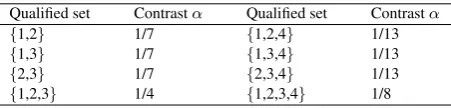
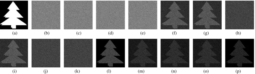
This experiment is conducted for the secret image of size1024× 1024shown in Fig. 1(a). The secret image is encrypted into four cipher grids (Figs. 1(b)-1(e)) for the access structure 1. Each cipher grid is meaningless and does not reveal the secret information. By the stacked images for the forbidden sets (Figs. 1(h), 1(j), 1(k)), no secret information can be revealed. The stacked images for the qualified sets (Figs. 1(f), 1(g), 1(i), 1(l)-1(p)) can visually reveal the secret image. Table 1 shows the contrast of the stacked images for the qualified sets of the access structure 1.
5.2 Experiment 2
[image:6.595.318.544.458.512.2]In this experiment, a color image of size1024×1024shown in Fig. 2(a) is encrypted into four cipher grids (Figs. 2(b)-2(e)) for the access structure 2. Each cipher grid is meaningless and reveals no secret information. The stacked images for the forbidden sets (Figs. 2(f), 2(g), 2(i)-2(l)) do not reveal any information about the secret image. The secret image can be easily recognized by the stacked images for the qualified sets (Figs. 2(h), 2(m)-2(p)).
Table 1. Contrast of the stacked images for the qualified sets of the access structure 1
Qualified set Contrastα Qualified set Contrastα
{1,2} 1/7 {1,2,4} 1/13
{1,3} 1/7 {1,3,4} 1/13
{2,3} 1/7 {2,3,4} 1/13
[image:6.595.301.572.569.667.2]{1,2,3} 1/4 {1,2,3,4} 1/8
Table 2. Comparison of the contrast between the proposed scheme and random-grid based VSS schemes
Scheme (2,2) (n, n) (k, n) Access structure
Kafri and Keren [6] 1
2 - -
-Shyu [13] 12 2n1−1 -
-Chen and Tsao [4] 12 2n1−1 -
-Chen and Tsao [5] 12 2n1−1
2×(t k) (2t+1)×(n
k)−( t k)
-Ours 1
2 2n1−1
2×(t k) (2t+1)×(n
k)−(kt)
2×c N×2t+N−c
(a) (b) (c) (d) (e) (f) (g) (h)
[image:7.595.56.557.66.212.2](i) (j) (k) (l) (m) (n) (o) (p)
Fig. 1 The experimental results of the proposed scheme for the access structure 1: (a) Binary secret image; (b)R1; (c)R2; (d)R3;
(e)R4; (f)R1⊗R2; (g)R1⊗R3; (h)R1⊗R4; (i)R2⊗R3; (j)R2⊗R4; (k)R3⊗R4; (l)R1⊗R2⊗R3; (m)R1⊗R2⊗R4;
(n)R1⊗R3⊗R4; (o)R2⊗R3⊗R4; (p)R1⊗R2⊗R3⊗R4.
(a) (b) (c) (d) (e) (f) (g) (h)
(i) (j) (k) (l) (m) (n) (o) (p)
Fig. 2 The experimental results of the proposed scheme for the access structure 2: (a) Color secret image; (b)R1; (c)R2; (d)R3;
(e)R4; (f)R1⊗R2; (g)R1⊗R3; (h)R1⊗R4; (i)R2⊗R3; (j)R2⊗R4; (k)R3⊗R4; (l)R1⊗R2⊗R3; (m)R1⊗R2⊗R4;
[image:7.595.315.562.512.584.2](n)R1⊗R3⊗R4; (o)R2⊗R3⊗R4; (p)R1⊗R2⊗R3⊗R4.
Table 3. Comparison of the contrast between the proposed scheme and Wu and Sun’s scheme [16]
Qualified set The proposed scheme Wu and Sun’s scheme [16]
{1,2} 1/7 1/19
{2,4} 1/7 1/19
{1,2,3} 1/13 1/17
{1,2,4} 4/25 1/19
{2,3,4} 1/13 1/17
{1,3,4} 1/13 1/17
{1,2,3,4} 1/8 1/17
5.3 Comparison with related work
A random-grid based(k, n)-threshold VSS scheme with2≤k≤
ncan be obtained as a special case of the proposed scheme by tak-ing the basisΓ0 = {Q ⊆ P : |Q| = k}. In this case, we have c = kt andN = nkfor any qualified set of t(≥ k) partic-ipants. Thus, the contrast (in Algorithm 4 based on Algorithm 1)
of the image obtained by stacking anytshares is 2×(
t k) (2t+1)×(n
k)−(kt)
.
Table 4. Comparison of the contrast between the proposed scheme and Shyu’s scheme [14]
Qualified set The proposed Shyu’s method Shyu’s method scheme by usingΓ0[14] by usingZM[14]
{1,2,3} 2/35 1/256 1/32
{1,2,4} 2/35 1/256 1/32
{1,3,4} 2/35 1/256 1/32
{2,3,4} 2/35 1/256 1/32
{1,2,3,4} 1/8 1/256 1/32
This is same as the contrast obtained in random-grid based(k, n )-threshold VSS scheme [5]. If we taket=n, then the contrast of the decoded image will be 1
2n−1, which is again same as obtained
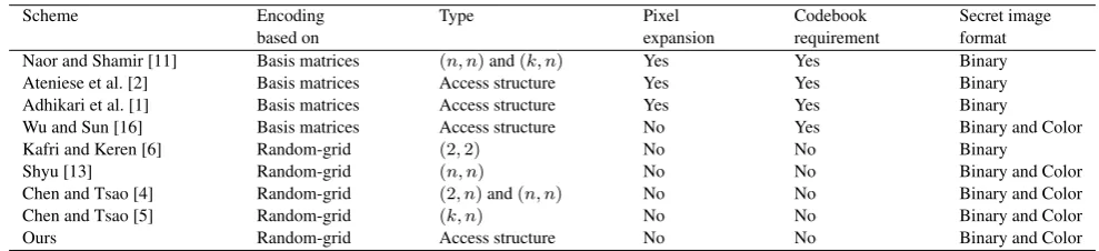
[image:7.595.54.292.512.593.2]Table 5. Comparison of the proposed scheme with related VSS schemes
Scheme Encoding Type Pixel Codebook Secret image
based on expansion requirement format
Naor and Shamir [11] Basis matrices (n, n)and(k, n) Yes Yes Binary
Ateniese et al. [2] Basis matrices Access structure Yes Yes Binary
Adhikari et al. [1] Basis matrices Access structure Yes Yes Binary
Wu and Sun [16] Basis matrices Access structure No Yes Binary and Color
Kafri and Keren [6] Random-grid (2,2) No No Binary
Shyu [13] Random-grid (n, n) No No Binary and Color
Chen and Tsao [4] Random-grid (2, n)and(n, n) No No Binary and Color
Chen and Tsao [5] Random-grid (k, n) No No Binary and Color
Ours Random-grid Access structure No No Binary and Color
P = {1,2,3,4}with the basis Γ0 = {{1,2},{2,4},{1,3,4}}
andZM ={{1,3},{1,4},{2,3},{3,4}}is taken. The following modified basis matrices are obtained by using the method discussed in [16], which are used to generate the shares.
BM 0 =
0 0 1 1 1 1 1 1 1 0 0 0 0 0 0 1 1 1 1 1 1 1 0 0 0 0 0 0 0 1 0 0 1 1 0 1 1 1 1 0 0 0 0 1 1 1 1 0 1 1 1 0 0 0 0 0
,B
M 1 =
0 0 1 1 1 1 1 1 1 0 0 0 0 0 1 1 0 1 1 1 1 1 0 0 0 0 0 0 0 1 0 0 1 1 0 1 1 1 1 0 0 0 1 0 1 0 1 1 1 1 1 0 0 0 0 0
.
Table 3 shows the contrast of the decoded images in the proposed scheme and Wu and Sun’s scheme [16] for the given access struc-ture. It is obvious that the proposed scheme can achieve higher contrast compared to Wu and Sun’s scheme [16]. Shyu’s scheme [14] adopts two different algorithms for encrypting a secret image into general access structures, i.e., by using the construction based on either basisΓ0 or collection of maximal forbidden setsZM. For comparison between the proposed scheme and Shyu’s scheme [14], the access structure defined on a setP = {1,2,3,4}with the basisΓ0={{1,2,3},{1,2,4},{1,3,4}{2,3,4}}andZM = {{1,2},{1,3},{1,4},{2,3},{2,4},{3,4}}is considered. Table 4 confirms that the proposed scheme can achieve higher contrast while comparing to algorithms proposed in [14].
In Table 5, the proposed scheme is compared with the related VSS schemes in terms of the pixel expansion, codebook requirement, type of the scheme and the secret image format. Compared to VSS schemes [1, 2, 11], the proposed scheme benefits by sharing binary as well as color images without any pixel expansion and codebook requirement. Compared to the proposed scheme, Wu and Sun’s scheme [16] can share the secret image for general access structures without any pixel expansion, but requires the basis matrices before encryption process. The proposed scheme generalizes the existing random-grid based VSS schemes [4–6, 13] to share a secret image for general access structures. Precisely, the proposed scheme for general access structures is obtained by extending the random-grid based algorithm and attains the security conditions perfectly, i.e., only qualified sets can recover the secret image while the forbidden sets cannot gain any information about the secret image.
6. CONCLUSION
In this paper, a VSS scheme for general access structures is de-signed based on random grids. The proposed scheme can be used to share a secret image into general access structures without any pixel expansion and codebook requirement. The security analysis and experimental results are given to confirm that the proposed scheme performs well. The potential applications of the proposed scheme may include image sharing, visual authentication, digital watermarking, image hiding, etc.
References
[1] A. Adhikari, T. K. Dutta, and B. Roy. A new black and white visual cryptographic scheme for general access structures. In Indocrypt’04, volume 3348, pages 399–413. LNCS, Springer-Verlag, 2004.
[2] G. Ateniese, C. Blundo, A. De Santis, and D. R. Stinson. Vi-sual cryptography for general access structures. Information and Computation, 129:86–106, 1996.
[3] G. R. Blakley. Safeguarding cryptographic keys.AFIPS Con-ference Proceedings, 48:313–317, 1979.
[4] T. H. Chen and K. H. Tsao. Visual secret sharing by random grids revisited.Pattern Recognition, 42:2203–2217, 2009. [5] T. H. Chen and K. H. Tsao. Threshold visual secret sharing by
random grids.The Journal of Systems and Software, 84:1197– 1208, 2011.
[6] O. Kafri and E. Keren. Encryption of pictures and shapes by random grids.Optics Letters, 12(6):377–379, 1987. [7] S. Kumar and R. K. Sharma. Improving contrast in random
grids based visual secret sharing. International Journal of Security and Its Application, 6:9–28, 2012.
[8] S. Kumar and R. K. Sharma. Recursive information hiding of secrets by random grids. Cryptologia, 37:154–161, 2013. [9] S. Kumar and R. K. Sharma. Threshold visual secret sharing
based on boolean operations. Security and Communication Networks, 2013. dOI:10.1002/sec.769.
[10] D. L. Lau and G. R. Arce.Modern Digital Halftoning. Marcel Dekker, New York, 2000.
[11] M. Naor and A. Shamir. Visual cryptography. InProceedings of Advances in Cryptology (EUROCRYPT 94), volume 950, pages 1–12. LNCS,Springer-Verlag, 1995.
[12] A. Shamir. How to share a secret. Communication of the ACM, 22(11):612–613, 1979.
[13] S. J. Shyu. Image encryption by multiple random grids. Pat-tern Recognition, 42:1582–1596, 2009.
[14] S. J. Shyu. Visual cryptograms of random grids for general access structures. IEEE Trans. on Circuits and Systems for Video Technology, 23:414–424, 2013.
[15] R. Ulichney.Digital Halftoning. The MIT Press, Cambridge, 1987.