VLSI Routing in Multiple Layers using Grid based
Routing Algorithms
Sonali Sen
St. Xavier’s College Kolkata
ABSTRACT
Aim of this paper is to describe a multi-layer grid routing algorithm which gives a better result over the existing algorithms. Given a multilayer grid routing area, considered the global routing problem of selecting a maximum set of nets, such that every net can be routed entirely in one of the given layers without violating the physical capacity constraints. The contribution of this paper is of threefold. First, we formulate the problem as an integer linear program (ILP). Second, we write an algorithm which proposed identical routing layers for each net using global routing .Our algorithm gives results which are guaranteed to be within a certain range of the global optimal solution and runs in polynomial-time. Finally we demonstrate that the complexity of our algorithm can be significantly reduced in the worst case prediction.
General Terms
VLSI RoutingKeywords
VLSI Routing, Global Routing, Grid based Routing, Multilayer Routing, Hadlock Algorithm.
1.
INTRODUCTION
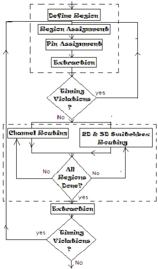
[image:1.595.347.508.238.511.2]The VLSI routing is a two phase process: global routing and detailed routing. Global routing is to find a loose path and detailed routing assigns the actual tracks and vias.
Fig. 1: Two Phase Routing Flow chart
Advances in VLSÍ fabrication technology have made it possible to use multiple routing layers for interconnections. Given a multilayer routing area and a set of nets, we consider the global routing problem of selecting a maximum (weighted) subset of nets, such that every net can be routed entirely in one of the given layers without violating the physical capacity constraints. This problem is motivated by the following:
i) Routing the majority of nets each in a single layer significantly reduces the number of required vias in the final layout. It is known that vias increase fabrication cost and degrade system performance.
[image:1.595.66.279.512.577.2]ii) Routing the majority of nets each in a single layer greatly simplifies the detailed routing problem in multilayer IC design.
Fig. 2: Two Phase Routing Flow chart
The objective of the routing problem is dependent on the nature of the chip. For general purpose chips, it is sufficient to minimize the total wire length, while completing all the connections. For high performance chips, it is important to route each net such that it meets its timing budget. Usually routing involves special treatment of such nets as clock nets, power and ground nets. In fact, these nets are routed separately by special routers.
2.
PROPOSED WORK
The paper has a threefold objective:
i) We formulate the multilayer global routing problem of selecting the maximum subset of nets such that every net can be routed entirely in one of the given layers without violating the physical capacity constraints, as an Integer Linear Program (ILP).
iii) We will try to demonstrate that the complexity of our algorithm significantly reduced.
2.1
MATHAMETICAL MODEL
In this section we introduce an ILP formulation for the global routing problem. An undirected grid graph G = (V, E) is constructed. In other words, a two—dimensional grid[1] is placed over the chip. For each tile, there is a vertex v € V, and two vertices corresponding to adjacent tiles are connected by an edge. In other words, each edge e € E represents a routing area between two adjacent tiles. In multilayer designs, an edge may consist of more than one layer. In particular, the following are given as inputs to the problem.
V: the set of vertices in the routing graph, |V| = N.
E: the set of edges in the routing graph, |E|= M.
L: {l, 2, . . . , L}: the set of available routing layers.
C e, l: the capacity of edge e € E on Layer l € L.
I: the set of nets. Each net i € I is defined by a subset of vertices Vi € V that need to be connected. In particular, a net i € I is realized by finding a Steiner tree that connects all vertices in Vi.
Ti : the set of all trees in G that can be used to realize net i € I. In other words every tree T € Ti Connects the vertices in Vi. It is worth noting that Ti can be exponentially sized our algorithm, however, do not require that the Sets Ti are explicitly given.
A net i € I is realized by findíng a Steiner tree T € Ti that is routed in one of the given layers l € L. The objective is to maximize the number of nets successfully realized.
The design variables are {xi (T,l): i € I , T € Ti , l € L } where for some i € I:
(1)
The global routing problem can be cast as ILP as follows:
(1a)
(1b)
(1c)
capac ity constraints. It ensures that the number of nets routed over
2.2 AN ALGORITHM FOR MULTIPLE
LAYERS ROUTING
There is a very well known algorithm for multiple layer routing- Hadlock’s minimum detour algorithm[2]. This algorithm uses A* search method and is a breadth-first search method. As a result, it finds a shortest path if one exists. In Hadlock’s Algorithm, the length of a path(P) connecting source and target is given by M(s,t)+2d(P) where M(s,t) is the Manhattan distance[3] between source and target and d(P) is number of vertices on path P that are directed away from the target. The length of P is minimized if and only if d is minimized as M(s,t) is constant for given pair of source and target. The detour number of a path is the number of times that the path has turned away from the target. The worst case time and space complexity of Hadlock’s Algorithm is O(n x m) for a grid of size n x m.
2.2.1 Modified Hadlock Algorithm
After studying past algorithms on Multiple layer routing [4] and planner algorithm for multilayer IC[5] we propose our algorithm by modifying the basic hadlock algorithm and split the result of the hadlock algorithm for given 5 layers in multiple layers available
For each edge between a pair of vertices in the path, we check whether the edge is vertical or horizontal. If it is vertical then we check either it is the even one or the odd one. If it belongs to the odd category then we place that edge in Layer 2. If it belongs to the even category then we place that edge in Layer 4. Again, If the edge is horizontal, then we check either it is the first one or the second or the third one. Accordingly, we place it in Layer 1, Layer 3 and Layer 5 respectively. This is how splitting is done.
Now the path resulted from the hadlock algorithm can be spited into 5 different layers (horizontal, vertical, horizontal, vertical, horizontal) using Split Algorithm. Thus we are able to reduce the number of connections per layer but the problem occurs if the capacity of the terminal is full then what? If an overlap occurs we will have two options and we select the next best path to route into the multiple layers.
To select the minimum path, first we find two different paths using Hadlock’s Routing Algorithm say P1 and P2. Then we check the length of both the paths. If the length of P1 path is less than that of P2 then we discard P2 and Split P1 according to the above Splitting Technique into Horizontal and Vertical Layers. Else if the length of P2 path is less than that of P1 then we discard P1 and Split P2 according to the above Splitting Technique into Horizontal and Vertical Layers.
Algorithm Split(P, Vertical, Horizontal) Begin
For each edge ei between pair of vertices vi and vi+1 in P do
End
Fig 3 : Split Algorithm
Algorithm SelectMinimum(s, m, t) Begin
Hadlock-Router(B, s, t, P1); Hadlock-Router(B, s, t, P2); if (Length(P1) < Length(P2) then)
Discard P2;
Split (P1, Vertical, Horizonta); elseif (Length(P2) < Length(P1)) then
Discard P1;
[image:3.595.341.519.402.590.2]Split(P2, Vertical, Horizontal); End
Fig 4 : Proposed Modified Hadlock
Now to check the efficiency we do an experiment by trial cases and compare to the efficiency of other algorithms[6]. The Experimental Results below shows the efficiency and the overlap problem and how to overcome it using above algorithms. We have taken two different test cases as examples with different starting and destination points.
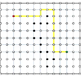
Example1:
Fig. 5: Output Path from Basic Hadlock Algorithm
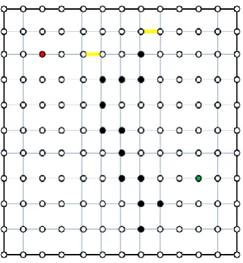
i. HORIZONTAL LAYER
ii. VERTICAL LAYER
iii. HORIZONTAL LAYER
[image:3.595.104.232.532.664.2]v. HORIZONTAL LAYER
Fig. 6: Connections on Different Layers
[image:4.595.349.507.70.448.2]Example2:
Fig. 7: Output Path from Basic Hadlock Algorithm
i. HORIZONTAL LAYER
ii. VERTICAL LAYER
iii. HORIZONTAL
Fig. 8: Output Path from Modified Hadlock Algorithm
Thus in fig 8(iii). We can see an overlap occurring which will be removed using the Select Minimum Algorithm that deals with two different cases.
Start with the initial state and find another path to the target.
Start with the last state where overlap occurred and find a path to the target.
We thus are able to find another best path from the Source to the target thus giving the best result.
2.3 WORST CASE COMPLEXITY
[image:4.595.87.245.520.689.2]2.4 CONCLUSION
The paper describes a multi-layer grid routing algorithm. Given a multilayer grid architecture we propose a routing algorithm for identical routing layers using global routing. This algorithm give results which are guaranteed to be within certain necessary constraints defined using a mathematical model which can be used to evaluate the sufficient condition. The algorithm, which keep the worst case time complexity as same as Hadlock’s algorithm, not only that it reduce the implementation complexity of each layer.
3.
REFERENCES
[1] Naveed Sherwani ,“Algorithms for VLSI Physical Design Automation” ,Third Edition.
[2] David Szeszler, “Combinatorial Algorithms in VLSI Routing” PhD Dissertation, 2005.
[3] Ion I. Mandoiu ,“Application Algorithms for VLSI Routing” , Georgia Institute of Technology, August 2000.
[4] Mohamed Saad, Anthony Vanelli and Hu Zhang, “A Global Routing Algorithm in Multilayer IC” , Lehigh University, Report-08T-004 June 5,2008.
[5] J.Cong, M.Hossain and N.A. Sherwani, “A Multilayer Topological Planar Routing Algorithm in IC Layout Designs” , IEEE Transactions on Computer Aided Design of IC and Systems,Vol12,no. 1,pp. 7078, Jan -1993.
[6] J.Cong, C.C. Chang, “An Efficient Approach to Multilayer Assignment with an Application”, IEEE Transactions on Computer Aided Design of IC and Systems, Vol-18, no. 5,pp. 608-620, Jan -1999.