Performance Analysis of DVB- T2 using MIMO-OFDM
Technique
Tawsif Hossain
Chowdhury
Department of Electrical and Electronics Engineering
American International University-Bangladesh
Sabbir-Ebna-Razzaque
Department of Electrical and Electronics Engineering
American International University-Bangladesh
Ajmery Sultana
Department of Electrical and Communication Engineering
University of Information Technology and Science
ABSTRACT
Orthogonal Frequency Division Multiplexing (OFDM) is a powerful technique employed in communications systems to combat with the frequency selective channel. Combined with smart antennas (multiple antenna system) at the transmitter and receiver, OFDM proves to be robust against channel delay spread. Moreover, it leads to significant data rates with improved bit error performance over links having only a single antenna at both the transmitter and receiver. In this work, the performance of the 2nd Generation Terrestrial Digital Video Broadcasting (DVB-T2) is analyzed, where high data rate is a must. To analyze this system, OFDM with Multiple-Input Multiple- Output (MIMO) systems have been used by applying an algorithm called Space-Time Block Code (STBC). Here, bit error rate (BER) of the system is analyzed in Additive White Gaussian Noise (AWGN) channel using QPSK modulation scheme. It has also been proved in this work that, the combination of OFDM-MIMO system is much more bandwidth efficient compared to normal OFDM system.
Keywords
Orthogonal Frequency Division Multiplexing (OFDM), Digital Video Broadcasting (DVB), Multiple-Input Multiple- Output (MIMO), Space-Time Block Code (STBC), AWGN, QPSK.
1.
INTRODUCTION
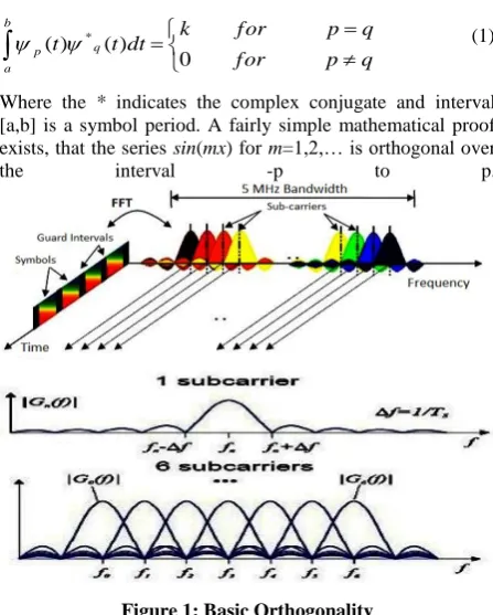
Orthogonal Frequency Division Multiplexing (OFDM) is an alternative wireless modulation technology to CDMA and it is suggested as the wireless access method for 4G systems. It is a modulation scheme that allows digital data to be efficiently and reliably transmitted over a radio channel, even in multipath environments. It transmits data by using a large number of narrow bandwidth carriers. These carriers are regularly spaced in frequency, forming a block of spectrum. The frequency spacing and time synchronization of the carriers are chosen in such a way that the carriers are orthogonal, meaning that they do not cause interference to each other. It can be simply defined as a form of multicarrier modulation where its carrier spacing is carefully selected so that each subcarrier is orthogonal to the other subcarriers. The entire bandwidth is filled from a single source of data. Instead of transmitting in serial way, data is transferred in a parallel way by using a large number of modulated sub-carriers. These sub-carriers (or sub-channels) divide the available bandwidth and are sufficiently separated in frequency (frequency spacing) so that they are orthogonal. Only a small amount of the data is carried on each carrier, and by this lowering of the bit rates per carrier (not the total bit
rates), the influence of Inter Symbol Interference (ISI) is significantly reduced. The orthogonality in OFDM system is shown in Figure 1. The orthogonality of the carriers means that each carrier has an integer number of cycles over a symbol period. Due to this, the spectrum of each carrier has a null at the center frequency of each of the other carriers in the system. This results in no interference between the carriers, although their spectra overlap. Mathematically, suppose a set of signals are Ψp(t) and Ψq(t) and the signals are orthogonal
if,
b aq p
q p f or
q p f or k
dt t t
0 ) ( ) ( *
(1)
Where the * indicates the complex conjugate and interval [a,b] is a symbol period. A fairly simple mathematical proof exists, that the series sin(mx) for m=1,2,… is orthogonal over
[image:1.595.316.540.358.637.2]the interval -p to p.
Figure 1: Basic Orthogonality
Figure 2: Orthogonality: Spectra of (a) four subcarriers, (b) individual subcarrier.
2.
OFDM TECHNIQUE
2.1
Basic Principle
The basic principle of OFDM is to split a high-rate data stream into a number of lower rate streams that are transmitted simultaneously over a number of subcarriers. The signal processing steps involved in OFDM system are shown in Figure 3. The main features of a practical OFDM system are as follows:
1. Some processing is done on the source data, such as coding for correcting errors, interleaving and mapping of bits onto symbols.
2. The symbols are modulated onto orthogonal sub-carriers. This is done by using Inverse Fast Fourier Transform (IFFT).
3. Orthogonality is maintained during channel transmission. This is achieved by adding a cyclic prefix to the OFDM frame to be sent. The introduced cyclic prefix can be used to detect the start of each frame. This is done by using the fact that the L first and last samples are the same and therefore correlated. This works under the assumption that one OFDM frame can be considered to be stationary.
4. Demodulation of the received signal by using FFT. 5. The channel can be estimated either by using a
training sequence or sending known so-called pilot symbols at predefined sub-carriers.
[image:2.595.315.491.218.384.2]Decoding and de-interleaving.
Figure 3: General OFDM Block Diagram
2.2
Single carrier vs. OFDM as multi
carrier
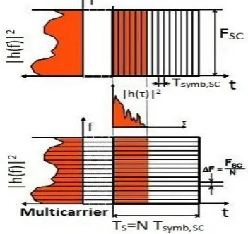
Let us consider a digital transmission scheme with linear carrier modulation (e.g. M-PSK or M-QAM) and a symbol duration denoted by Ts. Let B be the occupied bandwidth. Typically, B is of the order of Ts-1, for example, B = (1 + α) Ts-1 for raised-cosine pulses with roll off factor α. For a transmission channel with a delay spread τm, a reception free
of Inter-symbol Interference (ISI) is only possible if the condition τm «Ts is fulfilled [1]. As a consequence, the possible bit rate Rb= log2 (M) Ts-1for a given single carrier modulation scheme is limited by the delay spread of the channel. The simple idea of multicarrier transmission to overcome this limitation is to split the data stream into K sub streams of lower data rate and to transmit these data sub streams on adjacent subcarriers as shown in Figure 4. In OFDM, the entire channel is divided into many narrow sub channels, which are transmitted in parallel, thereby increasing the symbol duration and reducing the ISI. Therefore, OFDM is an effective technique for combating multipath fading and for high-bit-rate transmission over mobile wireless channels.
Figure 4: Signal Multicarrier
2.3
OFDM implementation
OFDM uses the principles of FDM to allow multiple messages to be sent over a single radio channel. It is however in a much more controlled manner, allowing an improved spectral efficiency. OFDM is symbol based, and can be thought of as a large number of low bit rate carriers transmitting in parallel.
Let
{
S
k}
kN01be the complex symbols to be transmitted by OFDM modulation; the OFDM (modulated) signal can be expressed as [2],
1
0
1
0
0 ),
( )
(
N
k
N
k
s k
k k
j
ke S t t T
S t
s
(2)Where, fk= fo + k f.
otherwise T t if e
t s
fkt j
k
0
0 )
(
2
(3)
For k = 0, 1,. . . , N-1. T and f are called the symbol duration and sub channel space of OFDM, respectively. In order for receiver to demodulate OFDM signal, the symbol duration must be long enough such that TS f = 1, which is also called orthogonality condition. Because of the orthogonality condition, it can have,
sT
l k s
dt t t
T 0
) ( ) (
1
s k lT
t f f j
s
dt
e
T
0) ( 2
1
= T
s j kl ft sdt e
T 0
) ( 2
[image:2.595.54.286.519.664.2]=[kl]
Where δ[k-l ] is the delta function defined as,
otherwise n if n , 0 0 , 1 ] [
(4)Using this property, the OFDM signal can be demodulated by,
s T tkt j sdt
e
t
s
T
0 2)
(
1
s T N l l l sdt
t
k
t
S
T
0 * 1 0)
(
)
(
1
=
1 0 ] [ N k k l sl
Sk
2.4
OFDM Generation & Reception
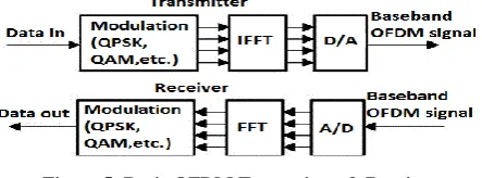
[image:3.595.316.538.438.587.2]The OFDM transmitter and receiver are illustrated in Figure 5. To generate OFDM successfully the relationship between all the carriers must be carefully controlled to maintain the orthogonality of the carriers. For this reason, OFDM is generated by firstly choosing the spectrum required, based on the input data, and modulation scheme used. Each carrier to be produced is assigned some data to transmit. The required amplitude and phase of the carrier is then calculated based on the modulation scheme (typically differential BPSK, QPSK, or QAM). The required spectrum is then converted back to its time domain signal using an Inverse Fourier Transform (IFFT). The Fast Fourier Transform (FFT) transforms a cyclic time domain signal into its equivalent frequency spectrum. The IFFT performs the reverse process, transforming a spectrum (amplitude and phase of each component) into a time domain signal.
Figure 5: Basic OFDM Transmitter & Receiver
2.5
OFDM Signal Model
In OFDM system design, a number of parameters are up for consideration, such as the number of subcarriers, guard time, symbol duration, subcarrier spacing, modulation type per subcarrier etc. Mathematically, the OFDM signal is expressed as a sum of the prototype pulses shifted in the time and frequency directions and multiplied by the data symbols. In continuous-time notation, the kth OFDM symbol is written [3],
0 , } ) ( Re{ ) ( 1 2 2 / ) )( ( 2 ,, kT T T t kT T T otherwise
e x kT t w kT t S win FFT guard win N N t kT t T t f j k i k RF
F F T c
(5)
A complete list of symbols is given here:
T: Symbol length; time between two consecutive OFDM symbols;
TFFT: FFT time; effective part of the OFDM symbol;
Tguard: GI; duration of the cyclic prefix;
Twin: Window interval; duration of windowed prefix/postfix
for spectral shaping;
fc: Center frequency of the occupied frequency spectrum; F =1/TFFT: Frequency spacing between adjacent SCs;
N: FFT length; number of FFT points; k: Index on transmitted symbol;
i: Index on SC; i ∈ {–N/2, –N/2+1, … –1, 0, 1, … N/2–1}; xi,k: Signal constellation point; complex {data, pilot, null}
symbol modulated on the ith SC of the kth OFDM symbol; w(t): The transmitter pulse shape, which is defined as,
win FFT FFT win FFT FFT guard guard guard win win guard win T T t T T T t T t T T t T T T T T t t w ) ( cos 1 2 1 1 ) ( cos 1 2 1 ) (
(6)
Finally, a continuous sequence of transmitted OFDM symbols is expressed as,
( ) )(t S t k T
SRF RFK
(7)
The simulated spectrum of such an OFDM signal is depicted in Figure 6 for different window lengths.
Figure 6: Spectrum of an OFDM signal with 64 SCs and different window lengths. Twofold oversampling has been
applied in the TD.48 SCs are used for data.
2.6
Guard Interval & Cyclic Extension
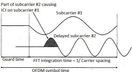
One of the most important reasons to do OFDM is the efficient way it deals with multipath delay spread. In the OFDM system two different sources of interference can be identified,1. Inter-symbol Interference (ISI) which is defined as the crosstalk between signals within the same sub-channel of consecutive FFT frames.
[image:3.595.56.278.453.535.2]Figure 7: The effect of delayed subcarrier 2 causing ICI on subcarrier 1 and vice versa
For the purpose of eliminating the effect of ISI and ICI, an idea is introduced called guard interval (sometimes called cyclic prefix) as shown in Figure 7. By using this, the symbol will be cyclically extended from the original harmonic wave of the Fourier period T by a guard interval of length to become a harmonic of the same frequency and phase, but of duration Ts= T + . This ensures that delayed replicas of the OFDM symbol always have an integer number of cycles within the FFT interval, as long as the delay is smaller than the guard interval. Since the insertion of guard interval will reduce data throughput, Tg is usually less than T/4. The reasons to use a cyclic prefix for the guard interval are:
To maintain the receiver carrier synchronization; some signals instead of a long silence must always be transmitted.
Cyclic convolution can still be applied between the OFDM signal and the channel response to model the transmission system.
3.
INPUT
MULTIPLE-OUTPUT (MIMO)
In wireless communication, multiple-input multiple-output, (MIMO) is the concept of using multiple antennas at both the transmitter and receiver to get improved performance. It is one of the newly marched smart antenna technologies. Note that the terms input and output refer to the radio channel that carrying the signal, not in terms of antennas. In Practical world, capacity and performances of wireless communication usually limited by two major impairments: multipath and co-channel interference. Multipath is a condition that arises when a transmitted signal undergoes reflection from various obstacles in the broadcast environment. This causes multiple signals arriving from different directions. Co-channel interference is the interference between two signals that operate at the same frequency. This is usually caused by a signal from a different cell occupying the same frequency band. Smart antenna is one of the most promising technologies which will allow a higher capacity in wireless networks by effectively reducing multipath and co-channel interference. In a Smart antenna system the arrays by themselves are not smart, it is the digital signal processing that makes them smart [4]. Recently, the research on multi-user MIMO technology has been emerging. MIMO is used because it has the capacity to efficiently deal with the problems created by multi-path channel.
3.1
Basic Principle
The core idea of MIMO is to use multiple antennas both for transmission and reception. This increases the capacity of the wireless channel. Capacity is expressed as the maximum
achievable data rate for an arbitrarily low probability of error. Hence, the thrust has been toward the development of codes and schemes that would enable systems to approach their Shannon capacity limit.
3.2
MIMO System Model
A MIMO system is considered with a transmit array of MT
antennas and a receive array of MR antennas and the block
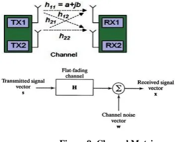
[image:4.595.323.542.173.310.2]diagram of such a system is shown in Figure 8.
Figure 8: Block diagram of a MIMO system. The transmitted matrix is a MT ´ 1 column matrix s where si is
the ith component, transmitted from antenna i. Consider the channel to be a Gaussian channel such that the elements of s are considered to be independent identically distributed (IID) Gaussian variables. If the channel is unknown at the transmitter, it can be assumed that the signals transmitted from each antenna have equal powers of Es /MT. The
covariance matrix for this transmitted signal is given by [5],
T
M T s
ss
I
M
E
R
(8)Where Esis the power across the transmitter irrespective of
the number of antennas MT and IMT is an MT ´ MT identity
matrix. It can be assumed that the channel matrix (Figure 9) is known at the receiver but unknown at the transmitter. The channel matrix can be estimated at the receiver by transmitting a training sequence. The elements of H can be deterministic or random. Each of the MR receive branches has
identical noise power of N0. The receiver operates on the maximum likelihood detection principle over MR receive
antennas. Since the total received power per antenna is equal to the total transmitted power, the SNR can be written as [5],
0
N
E
s
. (9)Therefore, the received vector can be expressed as [5], y = HS+ w (10) Where, y = Receive Vector.
S = Transmit Vector. W = Noise Vector. H = Channel Matrix.
2
,
2
1
,
2
2
,
1
1
,
1
h
h
h
h
H
Header
Figure 9: Channel Matrix
4.
SAPCE-TIME BLOCK CODES
The Alamouti Scheme
Space-time block coding (STBC) is a simple yet very effective means of achieving transmit diversity where other forms of diversity may be limited. This code can be used comprehensively in multiple receive antennas, that providing receive diversity in addition to transmit diversity. In space time block codes, codes are defined by transmission matrix with 3
parameters- Number of transmitted symbols l
Number of transmit antennas, Nt, defines the size of
transmission matrix.
Number of time slots in data block m
The ratio l/m defines of rate of code. The Alamouti scheme is a simplest STBC transmit diversity scheme suitable for two transmit antennas. Two symbols are considered at a time, say x1 and x2, and they are transmitted in two consecutive time slots. In the first time slot, x1 is transmitted from the first antenna and x2 is transmitted from the second one. In the second time slot, −x*2 is transmitted from the first antenna, while x*1 is transmitted from the second antenna. This process is illustrated in Figure 10. Since two symbols are transmitted in two time slots, the overall transmission rate is 1 symbol per channel use [6].
Figure 10: The Alamouti scheme.
5.
DIGITAL VIDEO
BROADCASTING-2
NDGENERATION TERREESTRIAL
(DVB-T2)
5.1
Basic Idea
DVB is a transmission scheme based on the MPEG-2 standard that delivers high quality compressed digital audio and video. DVB-T2 is an abbreviation for Digital Video Broadcasting – 2nd Generation Terrestrial; it is the extended version of the television standard DVB-T, issued by the consortium DVB, used for the broadcast transmission of digital terrestrial television. This system transmits compressed digital audio, video and other data in "physical layer pipes" (PLPs),
using OFDM modulation system with concatenated channel coding and interleaving. The higher offered bit rate, with respect to its predecessor DVB-T, makes it standard system for carrying HDTV signals on the terrestrial TV channel using OFDM modulation [7]. The spatiality of DVB-T2 is:
OFDM works by splitting the digital data stream into a large number of slower digital streams, each of which digitally modulated by the set of closely spaced adjacent carrier frequencies.
The terrestrial network operates in 1k, 2k, 4k, 8k, 16k, 32k mode.
DVB-T2 has a high flexibility because it allows the selection of the modulation scheme (QPSK, 16-QAM, 64-16-QAM,256-QAM)
DVB-T2 is specified for 1.7, 5, 6, 7, 8, and 10 MHz channel bandwidth.
Multiple PLP to enable service specific robustness.
Guard intervals are 1/4, 1/8, 1/16, 1/32, 1/128 etc.
For the commercial and technical requirement DVB-T2 would be devoted to provide optimum reception for stationary (fixed) and portable receivers.
The novel system should provide a minimum 30% increase in payload, under similar channel conditions already used for DVB-T [8].
5.2
Block diagram of DVB-T2
A general block diagram of DVB-T2 system is shown in the figure11.
Figure 11: DVB-T2 structure
There are some theoretical limits of the terrestrial transmission channel which must be considered 1st on the basis of an 8-MHz-wide channel. The maximum possible data rate in theory is expressed in approximation by the Shannon-limit via the following formula if the signal-to-noise ratio is about or more than 10 dB:
C = * B * SNR (12) Where, C = channel capacity (in bits/s);
B = bandwidth (in Hz);
[image:5.595.316.542.411.621.2]6.
SYSTEM DESIGN & SIMULATION
6.1
Transmission
This work is based on the 8k mode of the DVB-T2 standard. In this mode, the transmitted OFDM signal is organized in frames; each of them consists of 68 OFDM symbols. Each symbol is constituted by a set of K= 6817 carriers (actually sub carriers) and transmitted with a duration of Ts, composed of a useful part with a duration TU and a guard interval with a duration ΔT. Four frames make one super-frame. The numerical values for the OFDM parameters in the 8k mode are given in the table below:
Mode 8K
Elementary period, T 1/8 µs No. Max carriers, Kmax 6817 No min carrier ,Kmin 0
Duration , Tu 896 µs
Spacing betn carrier kmin &
kmax (k-1/tu) 8 MHz
Carrier spacing, 1/ Tu 1116 Hz
Allowed guard interval ,G 0, 1/4, 1/8 , 1/16 , 1/32 Duration of Guard interval ,
∆ = G * Tu 224 µs, 112 µs, 56 µs
Duration of Symbol , Tu 1k=2^10=1024, 8k=8*1024=8192
FFT /IFFT Length , Fs 8k+8k=16384 Total symbol duration,
Ts= Tu+ ∆ 896+224 µs, 896+112 µs
[image:6.595.322.531.75.340.2]A block diagram of the generation of one OFDM symbol is shown in the figure below. It can now proceed to describe each of the steps specified by the encircled letters in the figure below,
Figure 12: OFDM symbol generation simulation (Transmitter end).
In the Figure 12, the name of the variable used in the MATLAB code is under each encircled letter. Now, each of the steps specified in the figure above will be described. The total number of sub-carriers in this system is 6817. 16,384-6,817=9,567 zeros to the signal info at (A) are added to achieve over-sampling (2X) and to center the spectrum.
[image:6.595.49.286.199.509.2]
Figure 13: Time response of signal carriers
[image:6.595.330.524.434.670.2]Figure 14: Frequency response of signal carriers In Figure 13 and Figure 14, the result of the operation of IFFT can be observed and where the signal carriers at B have a time period of T/2. The signal carriers are a discrete-time baseband signal. The next step is to produce a continuous-time signal. In order to get that now it is required to sample the complex signal carriers with a transmit filter g(t). The period of the signal u(t) is 2/T. After sampling, The output of the filter, u(t) in time domain is shown below.
[image:6.595.57.275.582.630.2]digital-to-analog (D/A) filter is (2/T=16)-8=8 MHz. D/A filter has cut-off frequency close to 1/T. The next step is to convert it to a pass band signal using Quardrature multiplex double-sideband amplitude modulation. Double-balanced modulation can be defined as a modulation where the input to the filter does not contain the message signal or the carrier signal. In this modulation, an in-phase signal mI( t) and a Quardrature signal
mg (t) are modulated using the formula,
s(t) = mI(t)cos(2 fct) + mg(t)sin(2 fct) (13) Where, the in-phase signal mI(t) corresponds to the real part of the complex modulation symbols, whereas the Quardrature signal mg(t) corresponds to the imaginary part of the same complex modulation symbols. The next step is to perform the Quardrature multiplex double-sideband amplitude modulation of uoft(t), using the formula above.
s(t) = uoftI(t)cos(2 fct) + uoftQ(t)sin(2 fct) (14) The time response of the complete OFDM signal s (t) is shown below:
Figure 17: Time response of signal s(t) at (E). Figure 18: Zoom view of the transmitted data s(t) From the above figure, it can be seen that the transmitted data’s are overlapping with each another. It seems like the desire signal is being distorted due to high data rate. But by observing the corresponding figure with a zoom view, it can seen that there is no interference/overlapping of data sequences due to the orthogonality of the transmitting data’s. In this process very high data rate can be achieved. Now the signal will be transmitted through an AWGN channel.
6.2
Reception
[image:7.595.323.535.122.271.2]As mentioned before, the design of an OFDM receiver is open; i.e., there are only transmission standards. With an open receiver design, most of the research and innovations are done in the receiver. A basic receiver that just follows the inverse of the transmission process is shown in Figure 19.
Figure 19: OFDM reception simulation.
[image:7.595.57.266.298.502.2]The received signal converted into r(t) from s(t) after passing through the AWGN channel. After receiving the signal r(t), demodulate the signal with the corresponding carrier frequency fc. thus get r_tilde at F shown in figure 20.
[image:7.595.317.537.340.638.2]Figure 20: Time response of signal r_tilde at (F). In order to omit the high frequency component of the signal r_tilde, a low pass filter (LPF) is used. After filtering the signal, r_info will be found at G shown in Figure 21.
[image:7.595.61.279.694.738.2]
Figure 23: info_h constellation. Figure 24: a_hat constellation.
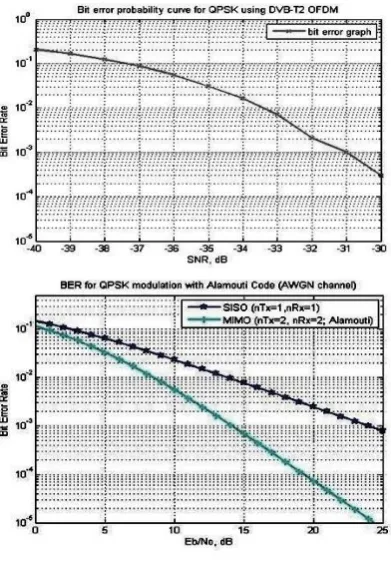
[image:8.595.66.262.446.728.2]The output of the FFT modulation block is the received constellation (info_h) in Figure 23. This one passes through a QPSK slicer, which assigns the received symbols into the four possible constellation points (a_hat constellation) in Figure 24. The error, which is a symbol error, is calculated by comparing the original constellation with the one that is outputted by the QPSK slicer. The simulation gave the following BER graph.
Figure 25: BER probability curve. Figure 26: BER comparison of SISO and MIMO
The graph Figure 25 shows that, the rate of errors in the transmitting data through AWGN channel using QPSK modulation scheme. From the graph it can be seen that if the SNR is decreased, the BER increases and with the increasing rate of SNR, the BER decreases. The graph Figure 26 shows the BER comparison between SISO & MIMO. From this graph it can seen that for certain energy of Eb/No the MIMO system has more superior performance than SISO system. Taking 20 db energy of Eb/No as an example, it is found that,
The BER of SISO system is 0.158%
The BER of MIMO system is 0.005%
Evaluating the above calculation, it can be concluded that, the bit error rate (BER) of MIMO system is 30-35 times better than that of SISO system.
7.
CONCLUSION
This work has investigated techniques that exploit the flexibility of OFDM-MIMO system to maintain a maximum spectral efficiency, by matching the system parameters, such as subcarrier modulation and frequency, based on current conditions of the radio channel. Also the bit error rate has been analyzed. This system transmits compressed digital audio, video, and other data in physical layer pipes (PLPs). The higher offered bit rate, with respect to its predecessor DVB-T, makes it a suited system for carrying HDTV signals on the terrestrial TV channel. In spite of the improvement of the bit error rate by using MIMO instead of SISO, there is more chances to work on MIMO system. In this work, DVB-T2 in 8k mode was investigated where the higher modes of DVB-T2 (i.e.: 16k or 32k) can also be used. This work was implemented using AWGN channel where the performances on other noise channels (i.e.: Rayleigh channel, Rician channel etc) could also be analyzed. So far in this work the simplest space-time block code which is 2x2 MIMO have been used, there are more scopes to work on n*n MIMO system which will further increase the outage capacity.
8.
REFERENCES
[1] L. Hanzo, W. Webb, and T. Keller, ‘Single- and Multi-carrier Quadrature Amplitude Modulation’. Chichester:IEEE Press and John Wiley & Sons, Ltd, 2nd edn, 2000.
[2] ‘Space-Time codes and MIMO Systems' - Mohinder Jankiraman.
[3] European Telecommunications Standards Institute, Radio Equipment and Systems (RES); High Performance Radio Local Area Network (HIPERLAN) Type 1; Functional specification, ETSI ETS 300 652 ed.1, October 1996.
[4] Digital Video and Audio Broadcasting Technology by
Walter Fischer - 3rd Edition.
[5] DVB-T2 technical details available at http://en.wikipedia.org/wiki/DVB-T2#Technical_details . [6] DVB-T2 Update Standardization, Performance, Service
Plans by Md. Sarwar Morshed. [7] A look inside DVB-T2.