Technology (IJRASET)
Can Based Data Display Unit Using Arm
Mahalaxmi R.Chougale1, Sadanand B.Kulkarni2
1
PG Student, VLSI Deign and Embedded Systems,2 Associate professor, Electronics and Communication K.L.E. DR. M. S. .Sheshgiri College of Engg & Technology, Belgavi, India
Abstract— this paper presents an overview of controller area network (CAN), its protocol and standards. CAN was developed by Robert Bosch in 1986 as a multi-master, message broadcast system specifically designed for automotive applications but today widely used in other fields too. It defines a standard for efficient and reliable communication between different communicating modules including the sensors, actuators, controllers, and other nodes in real-time applications. In this paper we propose a CAN based data display unit using LPC1768 ARM. The proposed system involves the CAN protocol to communicate the data. The system consists of two nodes each consisting of a LPC1768 ARM microcontroller and sensors. The data is retrieved from the sensor and forwarded to a LPC1768 ARM microcontroller through a CAN transceiver. The LPC1768 ARM microcontroller establishes connection with the CAN protocol and processes the sensor data through CAN bus. Another LPC1768 ARM microcontroller at remote end is interfaced with LCD to view sensor data. The high performance, low power consumption, inbuilt CAN functionality and other extensive features of LPC1768 ARM, make it a suitable choice for the implementation purpose.
Index Terms—Controller Area Network (CAN), LPC1768 ARM, sensors, CAN transceiver PCA82C250, ADC.
I. INTRODUCTION
The sensors, actuators, control units used in the control systems of various industries require some kind of communication network in order to communicate, share data with each other. For this purpose a CAN based communication network can be used. The CAN protocol is a serial communication protocol developed by Robert Bosch in 1986.The serial transmission of CAN offers advantage of reduced number of interconnecting lines over greater distances than that of point to point or even parallel transmission. The CAN bus is a fast serial bus which is intended to provide a reliable, efficient and cost-effective link between the various sensors, actuators and control units. Communicating media used for CAN is twisted pair of wires and it works at speeds up to 1 Mbits/sec. Most of the networked embedded control systems use CAN as the de facto standard.CAN is used in a variety of passenger cars, spacecraft, boats, trucks, and other types of vehicles .CAN is also widely used today in industrial automation and other areas of networked embedded control, with applications in diverse products. Comparing to the traditional control mode which follows a point to point style shown in figure.1, CAN bus has simple control structure, reduced number of wires as shown in figure.2. Thus CAN bus brings about higher reliability, maintainability and also ensuring real-time communication.
[image:2.612.238.375.524.716.2]Technology (IJRASET)
This paper presents an overview of controller area network, protocol and standards. Due to CAN reliability, efficiency and robustness, we propose a CAN based data display unit Using LPC 1768 ARM.
II. OVERVIEWOFCANPROTOCOL
CAN supports a multi-master style of network communication wherein any node on the CAN bus network can actively send messages at any point of time. Since the CAN protocol is a message based, nodes do not have specific address and the address information is stored in the identifier of the transmitted messages indicating the message content along with its priority. A major benefit of this message based protocol is that additional nodes can be added to the system without the need to reprogram all nodes. The CAN nodes have the ability to identify fault conditions as well as detect short disturbances from permanent failures. The CAN protocol provides sophisticated error detection and error handling mechanisms like cyclic redundancy check which helps in recovering the temporary errors while the nodes causing permanent errors are switched off.
[image:3.612.183.428.271.528.2]A.Architecture Of Can Protocol
Figure.1 show the architecture based on the OSI reference model. It is comprised of only three layers namely physical layer, data link layer and application layer.
Figure .3Architecture of CAN Protocol
B.CAN Communication Format
The two different versions supported by CAN (Version 2.0) are: CAN 2.0 A which is called the standard CAN, using 11 bits for node identification; and the other version is CAN 2.0 B which is called extended CAN, using 29 bits for node identification. The standard CAN With 11 bit identifier supports 2,048 unique messages, while the extended CAN with 29-bit identifier supports 536 million unique messages. All the messages can be seen by all the nodes-recipients in a controller area network, and the messages can be accepted or discarded accordingly as per the system design. The two CAN’s physical layer in terms of data rate is classified in two ISO standards namely ISO 11898 which handles speed up to 1 Mbit/sec and ISO 11519 which handles speed up to 125 Kbit/sec. The standard CAN and extended CAN are as shown in figure.4 and figure.5 respectively.
Technology (IJRASET)
The meaning of the bit fields of figure 4 are:SOF–stands for Start of Frame (SOF) bit. Whenever this bit is set high it marks the start of data transmission. This bit is used for synchronizing all the nodes on a bus after being idle.
Identifier-This Standard CAN 11-bit identifier helps in establishing the priority of the message. Always the lower binary value is assigned highest priority.
RTR–stands for remote transmission request (RTR) bit. Whenever information is required from another node, this bit is set high. The request will be received by all nodes but only the specified node will be determined by the identifier.
IDE– stands for Identifier extension. Whenever standard CAN identifier with no Extension is being sent this bit is set to high. R0– stands for reserved bit.
DLC–stands for data length code (DLC).This field indicates the number of bytes of data that are being transmitted. Data–This field indicates that Up to 64 bits of data may be transmitted.
CRC–This stands for 16-bit cyclic redundancy check (CRC) and is mainly used for error detection. It has the checksum (number of bits transmitted) of the prior data which is helpful for detecting the error.
ACK–Every node receiving an accurate message overwrites this recessive bit in the original message with a dominate bit, indicating an error-free message has been sent.
[image:4.612.185.426.550.702.2]EOF–This stands for end-of-frame (EOF) which indicates the end of the CAN frame transmission.
Figure.5 Extended CAN: 29 Bit Identifier
As shown in figure 5, the Extended CAN is the similar to the Standard CAN, but with the addition of 3 bit fields as follows: SRR–stands for substitute remote request (SRR) bit .This bit replaces the RTR bit in the standard message location as a placeholder in the extended format.
IDE–Whenever there is a recessive bit in the identifier extension (IDE) it means that more identifier bits tag along. The IDE is then followed by 18-bit extension.
R1– stands for reserved bit. This bit lies ahead of Data length code bit.
III. SYSTEMDESIGN
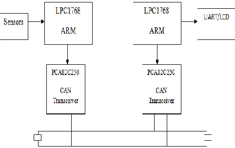
The proposed system comprises of two nodes namely transmitting node and display node, each consisting of a LPC1768 ARM microcontroller as shown in figure.6. The transmitting node consists of a gas sensor, LPC1768 ARM microcontroller and CAN transceiver PCA82C250. The data is retrieved from the sensor and transmitted to the LPC1768 ARM microcontroller. The analog sensor data is converted to digital form by the built-in ADC of the LPC1768 ARM, since the CAN bus accepts only digital signals.The digitally converted signals are then transmitted to the CAN Controller which implements the CAN protocol. The CAN transceiver provides interface between the nodes on the CAN bus.
Technology (IJRASET)
The display node consists of LPC1768 ARM microcontroller, CAN transceiver and a LCD Unit. The CAN transceiver provides interface with the node on CAN bus and also helps in receiving the sensor data from CAN bus and transmits it to the CAN controller which disconsolate the data frames received and sends the data to LCD. The high performance, low power consumption, inbuilt CAN functionality and other extensive features of LPC1768 ARM, make it a suitable choice for the implementation purpose.
.
IV. HARDWARE
The LPC1768 is an ARM Cortex-M3 based micro controller for embedded applications that require a high level of integration and low power dissipation. The LPC1768 ARM extends system enhancements such as efficient debug features and a high level of support block integration. The operating frequency of LPC1768 is up to100 MHz The peripheral complement of the LPC1768 includes up to 512 kilo bytes of flash memory, up to 64KB of data memory, Ethernet MAC, a USB interface that can be configured as either Host, Device, or OTG, 8 channel general purpose DMA controller, 4 UARTs, 2 CAN channels, 2 SSP controllers, SPI interface, 3 I2C interfaces, 2-input plus 2-output I2S interface, 8 channel 12-bit ADC, 10-bit DAC, motor control PWM, 4 general purpose timers, 6-output general purpose PWM, ultra-low power RTC with separate battery supply, and up to 70 general purpose I/O pins.
A. CAN Controller Specified By Lpc1768
The Architecture of CAN controller supported by LPC1768 ARM microcontroller is as shown in the figure.7
Figure.7 CAN Controller
There are two CAN controllers and buses. It Supports 11-bit identifier as well as 29-bit identifier. Bus access priority is determined by the message identifier (11-bit or 29-bit) .It has two Receive Buffers and Three Transmit Buffers. The common status registers deal with the status of the transmitted buffers. The acceptance filters are configured to check what kind of data is present in the receive buffers of CAN controller. They operate in three modes namely acceptance filter on-mode, off-mode and bypass mode. In the CAN core block the error management logic mainly deals with detecting of the errors using sophisticated error detecting schemes like cyclic redundancy check. Bit timing logic and bit stream processor are used to set clock for CAN protocol. The Programmable Error Warning Limit and Error Counters come along with read/write access. There is Arbitration Lost Capture and Error Code Capture with detailed bit position.
B. CAN Transceiver
Technology (IJRASET)
transmitter output stage against short-circuit to positive and negative battery voltage. Although the power dissipation is increased during this fault condition, this feature will prevent destruction of the transmitter output stage. If the junction temperature exceeds a value of approximately 160 C, the limiting current of both transmitter outputs is decreased. Because the transmitter is responsible for the major part of the power dissipation, this will result in reduced power dissipation and hence a lower chip temperature. All other parts of the PCA82C250 will remain in operation. The thermal protection is needed, in particular, when a bus line is short-circuited. The CANH and CANL lines are also protected against electrical transients who may occur in an automotive environment.
V. SOFTWARE
The C program for the system is written using Kiel IDE.
For the microcontroller to function Flash magic software has been used. Flash magic is a PC tool for programming flash based microcontrollers from NXP. The software design has been divided into initialization of the data transmitting section and receiving section.
A. Software Design Process Of Transmitting Node
The flowchart for the transmitting node is as shown in the figure 8.
In this section, the CAN controller is initialized. The transmit and receive buffers are also initialized. During the CAN registers the read and write buffers are immediately cleared by the system. The bit timing register, filter and mask register and the interrupt enable registers are then configured. Once the initialization of CAN controller is completed then the ADC and UART are enabled. The Analog-to-digital converter (ADC) converts the analog sensor data to digital signals. The operating mode of the acceptance filters is checked. When the acceptance filters are turned on, the sensor data is transmitted from transmit buffers and is received by receive buffers. In case of acceptance filters off mode the data is not accepted and is not stored in the receive buffers.
Figure.8 Flowchart for transmitting node
B. Software Design Process Of Data Display Node
Technology (IJRASET)
The CAN bus is read. The transceiver collects the data from CAN bus and forwards it to the LCD in order to view the sensor data. The LCD displays the current sensor data continuously.
Figure.9 Flowchart for receiving node
VI. RESULT
On the completion of hardware and software designs, the generated codes are compiled and downloaded in the LPC1768 ARM microcontroller for testing. Sensors are connected to the data transmitting node. The transmitting and display nodes are as shown in figure.10.After the required connections are made, the sensor data is processed through the CAN bus and is continuously displayed on the LCD at display node as shown in fiure.11.
Figure.10 Transmitting and Receiver units.
Figure.11 Display of sensor measurements.
VII. CONCLUSION
The use of CAN enables fast and reliable data transmission in comparison to the traditional point-to-point networks. The system designed offers advantages of portability, low power consumption, low cost and plug and play. A number of nodes as well as various types of sensors can be connected to the system designed as per requirements. The CAN based data display unit designed can be used in automobiles for speed, temperature, pressure, smoke, obstacle detection using speed, pressure, smoke, obstacle sensors respectively. It also finds applications in agriculture, greenhouse, healthcare, avionic fields, defense. Also the system can be used home and industrial automation.
REFERENCES
[1] Vijay Bhamare, Chirinjeevi, “CAN Based Real Time Implementaion in automobile using ARM”, International Journal of Advanced Research in Computer Engineering & Technology (IJARCET) Volume 2, Issue 3, March 2013.
Technology (IJRASET)
[3] Nanda Kumar G, Raj Narain B, “Portable embedded data display unit using CAN bus”, International Conference on Modelling, Optimization and Computing 2012.
[4] Ashwini S. Shinde, Prof. Vidhyadhar B. Dharmadhikar, “Controller Area network for automotive application”, ISSN 2250-2459, Volume 2, Issue 2, February 2012.
[5] H. F. Othman, Y. R. Aji, F. T. Fakhreddin, A. R. Al-Ali, “Controller Area Networks: Evolution and Applications”, IEEE, 0-7803-9521-2/06. [6] Steve Corrigan, “Introduction to the Controller Area Network (CAN)”, Texas Instruments.
[7]Piao Chang-hao, Chen Lu, CAO Ju, “A Design for Controller Area Network Bus Real-time Monitoring System”, International Conference on Computer Science and Network Technology, December 2011.
[8] SargunaPriya, Jothi Mani, Amudha, “Monitoring and Control System for Industrial Parameters Using Can
Bus”,International Journal of Engineering Trends and Technology (IJETT) –Volume 9 Number 10 - Mar 2014
[9] B. Praveen Kumar, V.Dhana Raj, BVV Satyanarayana,Dr. N S Murthy Sarma, “Design of Automatic Automobile using CAN Bus”, International Journal of Research in Computer and Communication technology, IJRCCT, ISSN 2278-5841,Vol 1, Issue 7, December 2012.
[10]Abu Asaduzzaman, Sandip Bhowmick, Md Moniruzzaman, “Design and evaluation of controller area network for automotive applications”, American Journal of Embedded Systems and Applications ,Vol. 2, No. 4, 2014, pp. 29-37, august 2014.