Journal of Chemical and Pharmaceutical Research, 2016, 8(5):265-272
Research Article
CODEN(USA) : JCPRC5
ISSN : 0975-7384
Validation and Optimization of Exhaust Gas Flow Control Parameters to
Control CO
2Emission with the Aid of Pre-heated ZSM-5 Zeolite Supported by
Lime Water Testing
Mylaudy S. Rajadurai
1, K. Kamalakkanan
2and
*Maroof Syed Ali M.
21Head R&D, Sharda Motor Industries Pvt Ltd, Mahindra World City, Chennai, Tamil Nadu, India 2
Department of Automobile Engineering, Hindustan Institute of Technology & Science, Hindustan University, Chennai, Tamil Nadu, India
_____________________________________________________________________________________________
ABSTRACT
Carbon dioxide emission control from automobiles termed to be the vast activity and various techniques were under
research to overcome this problem. One of the way to reduce the CO2from automobile is implementation of ZSM-5
Zeolite in the exhaust flow chamber. Here the zeolite was preheated to increase its porosity and ability to capture the carbon emission through exhaust. A separate chamber is designed with the aid of CATIA and analysed for optimized back pressure using STAR CCM and FLUENT. Parameters such as pressure drop, pressure, pressure flow, static pressure and turbulence were analysed and optimised to control the flow of exhaust gas through solid adsorbent, to increase the rate of adsorption and to enhance the retention time and porosity. Emission testing were taken out with the aid of AVL 444 N di-gas analyser in the presence of flow meter, testing results showed 5.89% reduction in CO2 and 9.44 PPM reduction in HC emission. Testing results were supported by lime water test for
confirmation.
Keywords: Zeolite, Adsorption, carbon capture, flow parameters, retention time, porosity.
_____________________________________________________________________________________________
INTRODUCTION
Vehicles powered by diesel engines were commercially used on large scale because of their reduced carbon-emission and energy consumption on comparing with gasoline engines. However, utilisation of gasoline engines were common among peoples for their personal transport. There is an urge to reduce the emission from internal combustion engines in order to overcome environmental issues such as global warming, icecaps, rise in temperature and air pollution. To reduce emission from internal combustion engines various emission methods were followed such as fuel modification, engine modification control through exhaust. The most viable and economic and economic way of controlling the emission to achieve partial zero emission is through emission control by exhaust, presently SCR, NCR, catalytic converter and muffler were employed in exhaust tailpipe in order to control emission through exhaust. Current researchers, researched about implementation of ZSM-5 zeolite in after treatment process to evolve the reduction of carbon-dioxide through exhaust emission.
The following are the equation described the difference between the formation of carbon-dioxide by theoretical and practical application
Theoretical combustion,
Fuel (HC) + Air (O2+N2) = CO2 + (H2O) + N2 (1)
Practical combustion,
Among the various adsorbent materials such as Alumina, Zeolite, Charcoal, NaKA, MoF, Limestone, Lithium hydroxide ZSM-5 found to have favourable Carbon-dioxide adsorption capacity through which regenerative process can be employed by which the absorbed carbon can be re-utilised for other chemical process.Yayat et.al in their paper Lampung Zeolite utilisation as gas emission adsorbent on charcoal making process investigated adsorption on charcoal making process investigated adsorption of gas emission in charcoal carbonisation furnace. The result shows positive lights of decreased Carbon-monoxide emission by 20 percentages, nitrogen by 85.9 percentage, and carbon-dioxide by 15.6 percentage. Additionally, on introducing Tio2,also shows additional 10 percentage decrease in
emission due to large pore volume. They compared surface area with pore total volume and average pore distance with every sampling. Also they experimented zeolite adsorbent with various TiO2[12].
Sang et.al researched about various Adsorbents in after treatment process which has optimal ability to absorb carbon-dioxide the research shows zeolite has favourable adsorption property. Their study shows zeolite supported
spinal oxide catalyst with ferrite and magnetite in presence of propane and methyl benzene exhibits better emission
control property through surface adsorption method [11]. Ocean et.al in their paper adsorption kinetics for carbon-dioxide for highly selective NaKA and NanoNaKA discussed about Carbon-carbon-dioxide removal through SAP which will reduce the cost of carbon capture and storage. They thoroughly discussed about property of zeolite NaKA with K+/(K++Na+) and their effect on carbon-dioxide and nitrogen adsorption is proportional to apertures. He used IR spectroscopy, TFT, to qualify carbon-dioxide adsorption and quantum chemical calculations. Nano NaKA shows apparently lower adsorption ratethan Zeolite NaKA [13].Rajadurai et.al in their paper materials for automotive exhaust system thoroughly discussed about various materials employed in exhaust system such as SUS441N &SUS310 etc in order to robust their physical, chemical and mechanical property also optimised the effect of after treatment chemicals in the exhaust material in order to provide high warranty condition [14,15].
In the current research pre-activated ZSM-5 zeolite pellets of high porosity property were utilised to absorb carbon-dioxide from exhaust gas through after treatment process. A separate reactor chamber was designed using Catia V5 and analysis were carried using FLUENT and STAR-CCM in order to optimised back pressure and exhaust flow. Emissions were measured using AVL444N Di-gas analyser. Additionally, lime water was carried out in which the results shows rate of limewater test was carried out in which the result shows rate of limewater conversion was reduced after the implementation of ZSM-5 zeolite adsorbent.
EXPERIMENTAL SECTION
Preparation of solid adsorbent
[image:2.595.184.408.533.640.2]ZSM-5 zeolite solid adsorbent of density 720kg/m3,19.8 percentage @15RH and 22.7 percentage @75RH water adsorption capacity with 2.45mm pore diameter at 4A0 was taken for experimental analysis on absorbing carbon-dioxide from exhaust gases through after treatment process. Initially ZSM-5 zeolite pellet was subjected to pre-activation process viz heat treatment in which zsm-5 zeolite pellets was heated continuously at mild temperature about 45-650c in order to activate the adsorption capacity. Table 1 shows the physical property of ZSM-5 Zeolite employed for adsorption process. Figure 1 Shows the close capture of ZSM-5 Zeolite pellets.
Figure 1. Close Capture of ZSM-5 Zeolite pellets
Table 1. Physical Property of ZSM-5 Zeolite employed for adsorption process
PROPERTIES VALUES
Pore size (nm) 0.5-1.5
A dedicated iso-cylindrical reaction chamber was designed in order to hold the ZSM-5zeolite pellets packed Inconel 600 fine wire mesh to withstand high temperature to absorb carbon emission from exhaust gas. The reaction chamber was featured with SUS 441N SS and ability to withstand at 1500oc.
A separate connection was designed in order to connect reactor chamber with exhaust tailpipe to carry out after treatment process. A flowmeter of 60000LPH was connected in series to calculate the air mass flow in extent in order to calculate the amount of emission per volume of air flow. The experimentation was carried out in Ford-Eco sport and AVL444N DIGAS analyser were used to measure emissions
RESULTS AND DISCUSSION
The design calculations and design validation for reaction chamber and emission results and calculations were to be discussed as follows
Design of reactor chamber
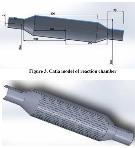
Based on catalytic converter used in sport vehicle of 1500cc was taken as a base design for drafting. The reaction chamber for after treatment process. Analysis were carried out in CFD fluent and STARCCM for the required boundary conditions to calculate the required back pressure, pressure flow, and turbulence inside the reaction chamber in the presence of adsorbent material. Figure 2,3,4 represents the various cross section of reaction chamber in CATIA [1].
[image:3.595.183.409.316.430.2]Figure 2. Design of Wire mesh for reaction chamber
Figure 3. Catia model of reaction chamber
[image:3.595.185.409.462.708.2]Design calculation
For the current reactor design base, calculations were optimised from the existing design in order to withstand the back pressure and turbulence created due to presence of solid adsorbent in the path, main parameters subjected to evaluation were as follows volume flow rate and reactor volume [2].
The space time required by volume of fluid to process one reactor is known as residence time. Here time taken per volume is coined as space volume. Standard space velocity of 30000hr-1 readings was calculated. Volume of flow depends on engine cylinder parameters.
Space Volume = (Volume flow rate) / Reactor volume (3)
By using the formula (ii) volume flow rate is calculated and identified as 70.8 m3 with respect to cylinder swept volume and intake strokes perhour.
Volume flow rate = Swept volume / Number of intake strokes per hour (4)
= 3.14* (bore/2)2 * stroke length* N/2* 60 = 3.14 * (0.079/2)2 * (0.0765) * (6300/2) * 60
Volume flow rate = 70.8 m3
Reactor volume stands as the main calculation to find out the volume of exhaust gas that can flow through the reactor chamber in the presence of packed pellets [3]. It is calculated using the formula (iii) considering the above calculated volume flow rate and space velocity.
Reactor Volume = Volume flow rate / Space velocity (5)
= 70.8/30000
Reactor Volume = 0.002356 m3
The Shell is the central cylindrical part between the inlet and outlet cones. This part comprises of tightly packed ZSM-5 Zeolite pellets inside the honey comb shaped wiremesh. Calculations were made for the volume of shell using the following formula (iv)
Volume of catalytic reactor = mm3
Where D – Diameter of the Reactor L – Length of the Reactor (assume L=3D)
Volume of catalytic reactor = 0.7853 * D2 * 3D (6)
0.002356 = 0.7853 * 3D3
D = 0.1000m = 10cm; L = 3D = 3*10 = 30cm.
Design validation
Initially reaction chamber modelled in CATIA was subjected to pressure analysis, velocity analysis, and turbulence flow analysis. The analysis was carried out in order to overcome the failure in after treatment process.
Validation of pressure analysis
Figure 5. Design Validation of Pressure drop
From figure 6 we can calculate the pressure, the pressure flow and static pressure inside the reaction chamber. Pressure seems to increase about 7.78 MPa at the adsorbent material due to rapid accumulation and decreased rate of flow through solid material with enhanced retention time which is essential for better adsorption. It can be noted that at the entry gas possess medium pressure of 3.66MPa than at the exit of 1.60MPa [5].
Figure 6. Pressure Validation of exhaust gas through reaction chamber
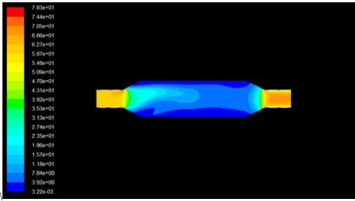
When pressure flow is manipulated, flow is high at both openings of about to 5.87MPa to 7.83MPa due to free flow of exhaust gas whereas the pressure flow drops in the body of the reaction chamber by 3.27MPa due to the pressure of solid adsorbent restricting the flow increasing rate of adsorption by increasing the relation time for higher space volume. Figure 7 shows the pressure flow validation [6].
\
Figure 7. Pressure flow Validation of exhaust gas through reaction chamber
Figure 8. Static Pressure Validation of exhaust gas through reaction chamber
Validation of turbulence analysis
[image:6.595.177.436.323.454.2]In order to optimise the back pressure to avoid back flow of the exhaust gas, turbulence inside the chamber is to be calculated since the pressure drop is high and lower static pressure. Turbulence was created due to the presence of solid material in the flowpath. It was examined from the figure that the turbulence was observed maximum at the backstage of the reactor body of about 9.8bar, whereas it was about 2.31bar to 4.11bar in the middle and 0.04bar at the entry of exhaust gas. Figure 9 represents the Turbulence validation [8].
Figure 9. Turbulence Validation of exhaust gas through reaction chamber
Emission result validation
Here main objective is to reduce the emission through exhaust gas with the aid of pre-treated ZSM-5 Zeolite pellets. Readings were taken before and after the implementation of solid adsorbent in the exhaust tail pipe also the validation was supported by lime water test. Testing’s were carried out in AVL444N Di-gas analyser, table 2 shows the specification of the analyser [9].
Table 2. Specification of flue gas analyser used for testing emission
Measured quality Measuring range Resolution Accuracy
CO 0 - 15% volume 0.01% Volume 0-10% ± 0.02%abs ±3%rel
10.01%- 15% ±5% rel
CO2 0 - 20% Volume 0.01% Volume
0-16% ± 0.3%abs ±3%rel 16.01%- 20% ±5%rel
HC 0 – 30,000ppm Volume ≥ 2000;10ppm Volume ≤ 2000;1ppm
0-4000ppm ±8ppm 3%rel 4000-10000ppm 5%rel 10001-30000ppm 10%rel
O2 0 - 25% Volume 0.01% Volume ±0.02% abs 1%rel
NO 0 - 5000 ppm Volume 1ppm Volume ±5ppm 1%rel
Engine speed 400 – 6000min -1 1min-1 ±1% of indicated value
Oil temperature 0 - 125ºC 1ºC ±4ºC
Lambda 0 - 9.9999 0.001 Calculation of CO2,CO,HC,NO
result was supported by limewater testing in which, rate of limewater turning milky was rapid and high before implementation whereas it is low after implementation [10].
Table 3. Measurement of emission from vehicle exhaust
S.NO Trials Condition RPM Mass flow rate (LPH) HC (ppm)
CO (% Vol)
CO2 (% by Vol)
O2 (% by Vol)
NOX
(ppm) Lambda
1
1 Before
700 5800
57 0.02 14.32 0.13 1 1.003
After 50 0.02 13.44 0.15 1 1.046
2 Before 56 0.03 14.34 0.05 2 0.998
After 53 0.02 13.53 0.20 1 1.028
3 Before 55 0.02 14.35 0.04 2 0.999
After 51 0.01 13.57 0.26 2 1.024
2
1 Before
1800 36000
51 0.02 14.27 0.05 2 1.001
After 44 0.02 13.22 0.15 1 1.005
2 Before 47 0.03 14.22 0.06 2 1.001
After 42 0.02 13.35 0.30 2 1.030
3 Before 45 0.04 14.22 0.03 2 1.001
After 39 0.03 13.38 0.09 2 0.999
3
1 Before
2500 60000
44 0.04 14.19 0.23 2 1.011
After 39 0.03 13.33 0.07 2 0.993
2 Before 38 0.04 14.15 0.20 3 1.001
After 37 0.02 13.36 0.45 2 0.999
3 Before 35 0.04 14.09 0.09 3 1.030
After 32 0.04 13.41 0.11 3 0.999
Table4 shows the average reduction in carbon-dioxide and hydro-carbon emission for the respective RPM. It shows that carbon-dioxide emissions is high at mid-range RPM than at lower and higher RPM same for the emission. Finally, 5.8% reduction in carbon-dioxide emission and 9.44ppm reduction in emission is achieved.
Table 4. Average reduction of emission from vehicle exhaust
S.NO CONDITION RPM MASS FLOW RATE (LPH) CO2% OF REDUCTION HC reduction in ppm
1 Before 700 5800 5.74 8.3
After
2 Before 1800 36000 6.46 12.56
After
3 Before 2500 60000 5.48 7.486
After
Average reduction of carbon-dioxide 5.89%
Average reduction of hydro-carbons 9.44 ppm
CONCLUSION
Following outcomes were achieved as a result of emission control using Pre-heated ZSM-5 zeolite filled such as,
• Specialised reactor chamber to hold ZSM-5Zeolite solid adsorbent was designed using CATIAV5 and analysis for supportive design was carried with aid of fluent and STARCCM.
• Design validation for following parameters was carried out such as pressure drop, pressure flow, static pressure and turbulence for exhaust flow inside the reactor chamber.
• Results of carbon capture through pre-heated ZSM-5 Zeolite shows 5.89% of carbon-dioxide reduction and 9.44ppm of hydro-carbon reduction. It was supported by limewater test in which the rate of limewater turning milky differs before and after implementation.
REFERENCES
[1]Leyla Vafi, Ramin Karimzadeh. Chinese Journal of Catalysis 2016, 37(4),628–635.
[2]Baijun Feng, Zhong Wang, Yuanyuan Sun, Chuanhui Zhang, Sifu Tang, XuebingLi, Xiang Huang. Catalysis
Communications 2016, 80, 20-23.
[3]Leyla Vafi, Ramin Karimzadeh. Journal of Natural Gas Science and Engineering 2016, 32, 1–9.
[4]Tuanny Santos Frantz, Walter Augusto Ruiz, Cezar Augusto da Rosa, Vanessa Bongalhardo Mortola.
Microporous and Mesoporous Materials 2016, 222, 209–217.
[5]Fatereh Dorosti, Mohammadreza Omidkhah, Reza Abedini. Journal of Natural Gas Science and Engineering
2015, 25, 88-102.
[6]Amin GhavamiNejad, Amin Kalantarifard, Go Su Yang, Cheol Sang Kim. Microporous and Mesoporous
[7]Chunyu Chen, Xiong Wang, Jian Zhang, Chaoqun Bian, Shuxiang Pan,Fang Chen, Xiangju Meng, Xiaoming Zheng, Xionghou Gao, Feng-Shou Xiao. Catalysis Today 2015, 258(1), 190-195.
[8]Kinga Góra-Marek, Kamila Brylewska, Karolina A. Tarach, Małgorzata Rutkowska, Magdalena Jabłońska, Minkee Choi, Lucjan Chmielarz. Applied Catalysis B: Environmental 2015, 179, 589-598.
[9]Max Hefti, Dorian Marx, Lisa Joss, Marco Mazzotti. Microporous and Mesoporous Materials 2015, 215, 215-228.
[10]Chang Hun Lee, Dong Hun Hyeon, Hyunchul Jung, Wonkeun Chung, Dong Hyun Jo,Dong Kun Shin, Sung Hyun Kim. Journal of Industrial and Engineering Chemistry 2015, 23, 251-256.
[11]Sang-Eon Park, Jong-San Chang, and Min Seok. activation of carbon dioxide as anoxidant over zsm-5 zeolite-supported metal oxide catalysts,Park Industrial Catalysis Research Lab., Korea Research Institute of Chemical Technology (KRICT), P.0.Box 107, Daeduck Danji, Taejeon 305-606,Korea
[12]Yayat Iman Supriyatna, David Candra Birawidha, Slamet Sumardi. International Journal of Civil &
Environmental Engineering IJCEE-IJENS Vol: 11 No: 02 54.
[13]Ocean Cheung, Zoltán Bacsik, Qingling Liu, Amber Mace, Niklas Hedin , Applied Energy 2013, 112, 1326– 1336.
[14]Mylaudy Dr. S Rajadurai1, J. Maya. International Journal of Recent Development in Engineering and
Technology 2015, 4(9).
[15]Mylaudy Dr.S. Rajadurai1, M. Afnas, S. Ananth, S. Surendhar. International Journal of Recent Development in