http://dx.doi.org/10.4236/jsip.2014.54013
A De-Noising Method for Track State
Detection Signal Based on EMD
Liming Li, Xiaodong Chai, Shubin Zheng, Wenfa Zhu
College of Urban Railway Transportation, Shanghai University of Engineering Science, Shanghai, China Email: [email protected], [email protected], [email protected], [email protected]
Received 14 August 2014; revised 10 September 2014; accepted 5 October 2014
Copyright © 2014 by authors and Scientific Research Publishing Inc.
This work is licensed under the Creative Commons Attribution International License (CC BY). http://creativecommons.org/licenses/by/4.0/
Abstract
In the track irregularity detection, the acceleration signals of the inertial measurement unit (IMU) output which with low frequency components and noise, this paper studied a de-noising algorithm. Based on the criterion of consecutive mean square error, a de-noising method for IMU accelera-tion signals based on empirical mode decomposiaccelera-tion (EMD) was proposed. This method can divide the intrinsic mode functions (IMFs) derived from EMD into signal dominant modes and noise do-minant modes, then the modes reflecting the important structures of a signal were combined to-gether to form partially reconstructed de-noised signal. Simulations were conducted for simulated signals and a real IMU acceleration signals using this method. Experimental results indicate that this method can efficiently and adaptively remove noise, and this method can better meet the pre-cision requirement.
Keywords
Track Irregularity, Signal De-Noising, Empirical Mode Decomposition, Consecutive Mean Square Error
1. Introduction
In using strap down inertial technology testing track irregularity, due to the track on a certain length of hori-zontal pendulum angle can’t be very big, the implementation of track inspection car speed is low, the inertial unit output value of the acceleration and angular velocity is small, and its output signal is very weak, and con-tains a certain amount of noise, easy to cause integrator saturation, thereby affects the detection accuracy of long wave irregularities [5]-[10]. This paper is based on EMD (empirical mode decomposition, the EMD) under the CMSE principles to collect inertial unit to deal with the noise signal, the experimental results show that the me-thod can effectively suppress noise and improve the detection accuracy.
2. Empirical Mode Decomposition (EMD)
2.1. The Definition Intrinsic Mode Function
According to different signal time scale, the EMD can decompose complex signal into several intrinsic mode function (intrinsic mode function, the IMF) arranging from high to low according to the frequency, so it can be seen as based on the extremum characteristic scale for measuring signal filtering process of space and time, can use this property to filter the signal analysis and de-noising [11]-[13].
After decomposition of each intrinsic mode function (IMF) meet the following two conditions:
1) Throughout the time sequence, the number of passing zero is equal to the number of the pole or at best, a difference;
2) At any point, the mean value composed of local maximum value upper envelope and lower local minima envelope must be zero.
2.2. The Basic Steps of EMD Decomposition
1) Find x t
( )
on all the maximum and minimum points, respectively, on the cubic spline interpolation to get the upper envelope xmax and lower envelope xmin. The mean value of envelope is defined as m t1( )
( )
( )
( )
1 min max 2
m t =x t +x t (1)
Using the original data after subtracting the mean can obtain:
( )
( )
( )
1 1
h t =x t −m t (2)
2) To determine whether h t1
( )
to meet the two conditions, if meet the h t1( )
is the first order of the IMF, otherwise the h t1( )
as a new signal repeat the above steps, so12 1 11
h = −h m (3)
Repeat the above process k times, when the variance between h1k and h1( )k−1 is satisfied the termination condition, such a h1k for the IMF, namely
( )
1k 1k 1 1k
h =h − −m (4)
Assuming that c1=h1k, define the remnants of the component for r1=x t
( )
−c1, repeat the above process, until rn or cn meet the termination conditions, end of the original signal EMD decomposition, finally get it( )
1 n
i n
i
x t c r
=
=
∑
+ (5)So you got the n IMF components and a residue signal. rn is residue components, representing average trend of the signal. And each IMF component c t1
( )
, c2( )
t , , cn( )
t respectively contains the signal from high to low different frequency components, and each frequency components that are included in the frequency changes over the signal itself.3. A De-Noising Method on EMD under Consecutive Mean Square Error Criterion
compo-nent of the IMF, reconstruct the signal
X
′
.The concrete definition formula of consecutive mean square error criterion CMSE as shown below:
(
)
( )
( )
2( )
2(
)
1 1
1 1
1 1
CMSE , IMF 1, , 1
N N
k k k i k i k i
i i
X X X t X t t k n
N N
+ +
= =
′ ′ =
∑
′ − ′ =∑
= − (6)Among them,
N
is the total length of signal. Based on the criterion, the cut-off point K is defined as:(
)
1 1 1
argmin k N CMSE K, k
K= ≤ ≤ − x′ ′x+ (7)
Namely find the global minimum position of the IMF as the cut-off point K of dominant mode of noise and dominant mode of signal, then find the noise energy distribution mutation of the Kth of IMF component cor-responding in Equation (7), then use all the IMF from K+1 to reconstruct the signal:
( )
( )
1 N
i i k
X t imf t
= +
′ =
∑
(8)Collected at the scene of the track state detection, the sensor signals in the process of converted into digital signals, test circuit noise and the external environment, the influence of such factors as the observed acceleration signal in computer is mainly composed of periodic components, constant and noise. Therefore Formula (9) can be used to describe the acceleration signal:
( )
sin(
0)
( )
, 0,1, 2, 3, , 1f t =A ωt+ϕ + +µ σ t t= n− (9)
In the formula, A—amplitude;
ϕ
—initial phase; ω0—fundamental frequency;µ
—directly current;( )
tσ —Gaussian white noise.
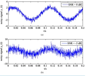
Using the EMD de-noising method under the rule of CMSE, to deal with the noise signal y t1
( )
, y2( )
t re- spectively, among them, y t1( )
, y2( )
t are made by stationary signal resulting from the Gaussian white noise.Signal-to-noise ratio of y t1
( )
is 8 db, signal-to-noise ratio of y2( )
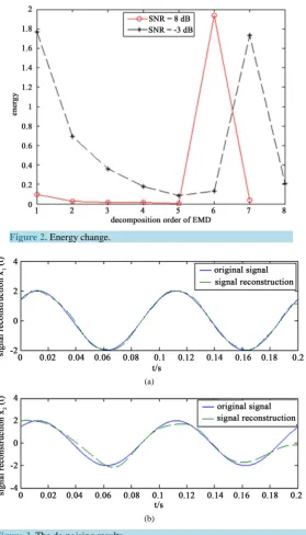
t is −3 db, as shown inFigure 1. Figure 2is y t1
( )
, y2( )
t ’s energy curve after the EMD decomposition of each IMF component. Signal y t1( )
, y2( )
tafter the EMD decomposition dominant mode of noise and dominant mode of signal of the cut-off point is 5, and then to the order of the IMF restructuring after de-noising signal, respectively, as shown in Figure 3.
(a)
[image:3.595.157.444.450.701.2](b)
Figure 2.Energy change.
(a)
(b)
Figure 3. The de-noising results.
From Figure 3, the higher signal noise ratio (SNR), the de-noising effect is better; in low signal noise ratio (SNR), changed obviously after de-noising signal distortion. This shows that the de-noising method on EMD under consecutive mean square error criterion in the case of low signal noise ratio (SNR) de-noising perfor-mance is unstable [16]. The cause of this unstable basically has the following two points:
1) “One size fits all” approach only focus on who play a leading role in the IMF component, while ignoring the fact that useful signal in dominant mode of noise’s proportion is big, that remove noise but also remove the useful signal by mistake;
2) for any noise signal, the algorithm considered in the curves of the IMF's energy minimum weight must be a dominant mode noise of the IMF, however, under the condition of low signal noise ratio (SNR), the rule does not necessarily is founded.
the local minimum value, the influence of the reason for (7) modified as follows: If the local minimum value exists before the global minimum, then
(
)
1 1 1
arg firstlocal min k N CMSE K, k 1
K= ≤ ≤ − x′ ′x+ +
else, K=argmin1≤ ≤ −k N 1CMSE
(
xK′ ′,xk+1)
+1.4. The Analysis of Experiment Results
Experiment system uses XW-IMU5250 tiny mechanical inertial device of Beijing Star Neto Technology Devel-opment Co., Ltd., used as shown in Figure 4shows the simulate rail cars as the carrier of strap down inertial system, in the process of experiment, to reduce the vector relative to the movement of the inertial measurement unit, inertial measurement unit should be installed in the center of gravity of the simulate rail cars, so as to im-prove the measurement accuracy of accelerometers.
In the experiments for loading of the inertial measurement unit testing the car through an analog line segments, and then collect the inertial measurement unit acceleration among the car movement. First of all, using the av-erage filtering method to eliminate the acceleration signal contained in the direct current; Then this method is applied to the actual inertial unit signal noise processing.
With IMU5250 output
y
axis acceleration signal as an example, the first of the acceleration signal of iner-tial measurement unit attitude matrix transformation, transformation to the geographic coordinates, then the EMD decomposition based on continuous root mean square error criterion. As shown in Figure 5, the first line is original signal and from the top down is, in order, each IMF component after the EMD decomposition, calcu-late each IMF component then get the curve energy of the y axis acceleration signal. [image:5.595.127.481.356.710.2]
Figure 4.The track on experimental platform.
Figure 5. IMF components of acceleration signal on y-axis after EMD decomposition.
0 100 200 300 400 500 600 700 800
-0.1 0 0.1
0 100 200 300 400 500 600 700 800
-0.02 0 0.02
0 100 200 300 400 500 600 700 800
-0.1 0 0.1
0 100 200 300 400 500 600 700 800
-0.05 0 0.05
0 100 200 300 400 500 600 700 800
-0.1 0 0.1
0 100 200 300 400 500 600 700 800
-0.1 0 0.1
0 100 200 300 400 500 600 700 800
-0.1 0 0.1
0 100 200 300 400 500 600 700 800
-0.05 0 0.05
0 100 200 300 400 500 600 700 800
-0.05 0 0.05
0 100 200 300 400 500 600 700 800
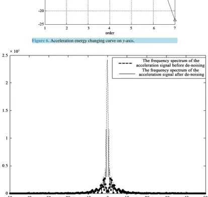
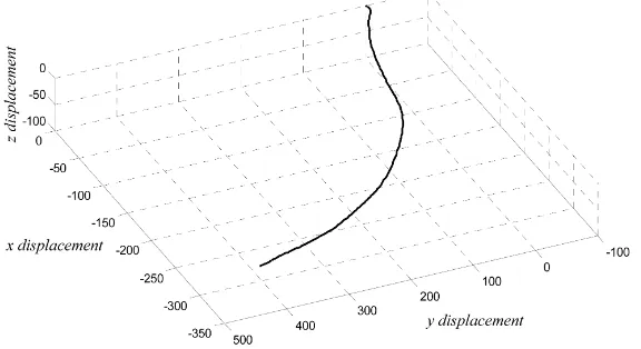
FromFigure 6obtain the cut-off point K of dominant mode of noise and dominant mode of signal, respec-tively, k1=6, k2=3, k3=3. According to the cut-off point, remove the IMF component after k+1, and then reconstructed the remaining component of signal. Acceleration signal after the restructuring, again carries on the frequency domain analysis, frequency spectrum diagram as shown in Figure 7. Using the EMD de-nois- ing method based on continuous mean square error, low frequency part of signal spectrum diagram can be seen that the method can effectively remove the low frequency component in the signal. In Figure 8, we can get the trajectory using the experimental method, which is in accordance with the actual test vehicle through track seg-ments.
Figure 6. Acceleration energy changing curve on y-axis.
[image:6.595.90.504.307.698.2]Figure 8.Spatial linear displacement.
5. Conclusion
This paper puts forward a kind of de-noising method for track state detection signal based on EMD under the CMSE principles, at the same time fixed the judgment methods of cut-off point K, and is applied to test signal and the inertial measurement unit output of the acceleration signal de-noising. The experimental results show that the method can carry on the noise to the signal processing, filter out low frequency noise in dealing with the inertial measurement unit signal shown good performance, also for the inertial measurement unit of the signal processing in the future to provide certain reference.
Acknowledgements
The project is jointly supported by the Shanghai Tertiary Education Speicalized Fund for Planning to Support Young Teacher’s Trainnings (ZZGJD12007), the Natural Science Foundation of Shanghai (12ZR1412300), the Science and Technology Commission of Shanghai Municipality Key Support Project (13510501300), and the Shanghai Graduate Education Innovation Project in Layout and Construction Project (13sc002).
References
[1] Zheng, S.B., Lin, J.H. and Lin, G.B. (2007) Maglev Track Long-Wave Irregularity Detection Based on Inertia Method and Its Implementation. Journal of Electronic Measurement and Instrument, 21, 61-65.
[2] Zheng, S.B., Lin, J.H. and Lin, G.B. (2007) High-Speed Maglev Track Long-Wave Irregularity Detection System De-sign. Chinese Journal of Scientific Instrument, 28, 1781-1786.
[3] Du, H.T. (2000) Long Wavelength Track Irregularity Detection Method of Digital Filter. China Railway Science, 4, 58-64.
[4] Zhu, H.T., Cai, J. and Wang, Z.Y. (2007) Based on the Orbit of Fiber Optic Gyroscope Direction Irregularity Detection System. Microcomputer Information, 23, 268-269.
[5] Boudraa, A.O. and Cexus, E.-C. (2007) EMD-Based Signal Filtering. IEEE Transactions on Instrumentation and Mea- surement, 56, 2196-2202. http://dx.doi.org/10.1109/TIM.2007.907967
[6] Tan, S.W., Qin, S.R. and Tang, B.P. (2004) The Hilbert-Huang Transform Filtering Properties and Application. Jour-nal of Chongqing University, 27, 9-14.
[7] Zhao, W.W. and Zeng, X.W. (2008) A New Method of EMD De-Noising. Electronic Science and Technology, 5, 30- 32, 36.
[8] Zhu, W.F., Chai, X.D. and Zheng, S.B. (2012) Based on the Integration Filter Displacement Information Acquisition.
Instrument Technique and Sensor, 11, 87-90.
[9] Ren, C.H., Xiong, L.X. and Zhao, X.J. (2010) Wavelet Threshold Filtering in Signal Processing, the Application of Fiber Optic Gyroscope. Piezoelectrics & Acoustooptics, 32, 957-959.
[10] Wang, T. (2010) The EMD Algorithm and Its Application in Signal Denoising. Haerbin Engineering University, Haer-bin.
3611-3616.
[12] Antonino-Daviu, J., Roger-Folch, J., Pons-Llinares, J., Pineda-Sanchez, M., Perez, R.B. and Charlton-Perez, C. (2011) Application of the Empirical Mode Decomposition to Condition Monitoring of Damper Bars in Synchronous Motors.
Industrial Electronics (ISIE), Gdansk, 27-30 June 2011, 2118-2123.
[13] Yang, G.L., Zhu, Y.Q. and Yu, H.Y. (2010) The Automatic Seismic Signal Denoising Algorithm Based on HHT.
Journal of Geodesy and Geodynamics, 3, 39-42.
[14] Zhu, L.P., Liu, A.J. and Wang, H.X. (2011) Based on the Radar Clutter Suppression of HHT. Modern Defense Tech-nology, 6, 185-190.
[15] Gao, Y.C., Sang, E.F. and Liu, B.F. (2007) The Adaptive De-Noising Algorithm Based on Empirical Mode Decompo-sition. Computer Engineering and Applications, 43, 59-61.