© 2016, IRJET | Impact Factor value: 4.45 | ISO 9001:2008 Certified Journal
| Page 177
Skew Effect on the Design of Composite Super Structures in Bridges
Manjunath K
1, H. R. Prabhakara
2, Mahadev M Achar
31
PG Student, M.Tech CAD Structures, UBDTCE, Davangere. Karnataka, India
2Professor Department of Civil Engineering, UBDTCE, Davangere. Karnataka, India
3
Senior vice President, Transys Consulting Pvt. Ltd. Bangalore, Karnataka, India.
---***---Abstract -
The presence of skew in a bridge makes the analysis and design of bridge complex. Design of bridges by considering skew angle is becoming more customary in the engineering community, so there is a need for more research to study effect of skew angle on the behaviour of skewed bridges such as bending moment, shear force, torsion and other parameters. This study mainly focuses on the effect of skew angle on the design of composite super structures in bridges. Six models have been developed and analyzed by using Finite element based software CSi Bridge 2015 (Advanced Version). Skew angles are taken as 00, 100, 200, 300, 400 and 500, and all models were subjected to IRC class A and IRC class 70R vehicle loading. Results for skewed bridges are compared to the straight or non-skewed bridges.Key Words: Bridges, Skew angle, FEM, Girders, Dead load and live load.
1. INTRODUCTION
Bridge is a structure which covers a gap, generally these structures will carry a road or railway over an obstacles such as natural or artificial obstacles like a canal, river or roadway or railway. Bridge is the most significant component of a transporting system and it is corresponding to the responsibilities in carrying a force flow of transport. These structures are classified on the basis of distribution of forces in the structure such as shear, compression, tension and moment.
1.1 Composite Bridge
Where a RC deck slab casted on top of several I-steel girders side by side and act as composite in them in bending. Composite action is developed by connecting shear connectors on top flange of the steel girder by welding. The deck slab cast around the shear connectors. The steel girders may be rolled sections, for short spans, or can be fabricated from plate. Girders are launched by providing stiffeners to web and resting on bearings. Effective span of these bridges about 25 meters to 150 meters are applied.
1.2 Skewed Bridges
[image:1.595.318.548.353.477.2]
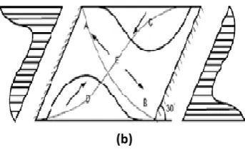
The term angle of skew or skew angle is generally applied to the difference between the normal to the centreline of the bridge and the centreline of the abutment or pier cap. In earlier days, they used to prevent skew bridges as far as feasible due to lack of information about structural behaviour and construction difficulty.But in the recent days there is rising trend to provide skewed composite bridges compare to straight bridges.
Figure 1 : Plan of skew bridge
1.4 behaviour of bridge decks
In straight bridges, the deck slab is perpendicular to the supports and the load path is straight towards the support shows in figure 1.2 (a) .Whereas in skewd bridges the load tends to take shortest path to the nearest supports as shown in figure 1.2 (b) and it is complicated problem because in which direction slab will span and the manner in which load will transfer to the supports due to skew in bridge.
© 2016, IRJET | Impact Factor value: 4.45 | ISO 9001:2008 Certified Journal
| Page 178
[image:2.595.74.246.106.211.2](b)
Figure 2: Behaviour of bridge decks
1.4 Advantages
1) These bridges are encountered in highway design when the geometry of structure cannot accommodate straight bridges.
2) These bridges consumes less space compare to other straight bridges
3) Bridges can be constructed even in congested place if skew bridges are designed properly done.
4) Skew bridges are more efficient in urban areas because lack of space required constructing traditional non skewed bridges.
1.5 Disadvantages
1) In skew bridge the force flow is much more complicated as compared to normal straight bridges
2) Under service load and seismic load skew bridges makes their behaviour more complex
1.6 Objectives
1) The objective of analysis is to study on the behaviour on entire bridge section under different loading conditions such as dead load of whole structure, live load of IRC A and IRC 70R loading with the presence of skew angle in bridges section.
2) The objective is to study the structural behaviour in each individual girders of a bridge section under the various loading conditions such as IRC A loading and IRC 70R loading with varying in skew angles.
2. PARAMETRIC STUDY
A 3 lane, 3D bridge model of span 30 m, width 12 m and effective span 28.52m, has been taken. Total six bridge models are considered of steel I-beam girder with deck slab and various skew angles of 00.100, 200, 300, 400 and 500 to know the effect on the composite superstructure (i.e. steel girder and concrete deck slab) with presence of skew angle in the bridge. The number of longitudinal girders has been taken 4. End lifting beams provided to avoid the toppling of longitudinal girders. POT cum PTFE bearing are used, thickness of wearing course 50 mm and standard New Jersey crash barrier provided. All models were analyzed for dead load and two classes of live load i.e. IRC Class A and IRC Class 70R.
Table 2: Section details I – Flange section
Section Name : Longitudinal Main Girder
Outside height 1.322 m
Top flange width 0.500 m
Top flange thickness 0.032 m
Web thickness 0.014 m
Bottom flange width 0.600 m
Bottom flange thickness 0.040 m
Section Name: End lifting beam
Outside height 0.900 m
Top flange width 0.300 m
Top flange thickness 0.025 m
Web thickness 0.012 m
Bottom flange width 0.300 m
Bottom flange thickness 0.025 m
Section Name: X- Bracing ISMC 100
Outside depth 0.100 m
Outside flange width 0.050 m
Flange thickness 0.0075 m
Web thickness 0.047 m
Table 3: Span items
Span Diaphragm property Distance in m Location Span 1 End lifting beam 0.000 All spaces Span 1 X- Bracing 7.130 All spaces Span 1 X- Bracing 14.260 All spaces Span 1 X- Bracing 21.390 All spaces Span 1 End lifting beam 28.520 All spaces
4. FINITE ELEMENT METHOD
It is a numerical technique for obtaining approximate solution of partial differential equation. FEM helps in producing stiffness and strength visualization, also to minimize the weight of material cost of the structure. FEM indicate the distribution of stress and strains and also it gives detailed visualization of a body.
© 2016, IRJET | Impact Factor value: 4.45 | ISO 9001:2008 Certified Journal
| Page 179
Figure 3: 3D view of composite bridgeFigure 4: Plan of skewed bridge section
5. RESULTS AND DISCUSSIONS
The project work carried out to determine the skew effect on the design of composite super structure of a bridge. Total six models were modelled, bridge of span 0 m, 3.565m, 7.130m, 10.695m and 14.260m were analysed for skew angles of 00, 100, 200, 300, 400, and 500.
The FEA results are obtained and presented in term of structural response parameters such as longitudinal bending moment, Shear force and Torsional moment due to dead load of the structure and applied live load. The variations in behaviour of structure due to changes in skew angles are presented as follows.
Entire Bridge Section Bending moment
Table 4: Bending moment due to DL and LL in kN-m Skew
angles in
degrees Dead load
Class A
Loading Class 70R Loading
0 11619.068 7480.228 5329.208
10 11590.805 7439.239 5567.771
20 11484.207 7393.680 5794.312 30 11241.128 7266.659 5837.264 40 10775.642 6917.342 5837.989 50 9964.306 6186.622 5458.091
Figure 3: Skew angle vs bending moment
The maximum bending moment due to dead load is observed at 00 skew angle bridge, as increase in skew angle the bending moment also decreases. In case of class A loading also maximum bending is observed for 00 skew angle bridge. Whereas in case of class 70R loading, the bending moment is maximum at 300 skew angle bridge
Shear force
Table 5: Shear force due to DL and LL in kN
[image:3.595.317.552.376.661.2]
Figure 6: skew angle vs shear force
From figure 6, the maximum shear force due to dead load is almost same for all skewed bridges. Due to class A loading the shear force is maximum in 200 bridge, after 200 skew the shear force is decreasing gradually. In case of class 70R loading also shear force deceases due to increasing in skew angle.
Skew angles in
degrees
Dead load Class A loading
Class 70R loading
0 1622.749 312.550 257.098
10 1622.822 314.155 245.005
20 1623.051 315.170 235.357
30 1623.479 295.221 219.208
40 1624.191 289.191 220.060
[image:3.595.48.272.631.744.2]© 2016, IRJET | Impact Factor value: 4.45 | ISO 9001:2008 Certified Journal
| Page 180
Torsion
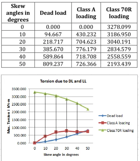
Table 5: Torsion due to DL and LL in kN-m Skew
angles in
degrees Dead load
Class A
loading Class 70R loading
0 0.000 0.000 3278.099
10 94.667 430.232 3186.950 20 218.717 704.623 3040.191 30 385.670 776.179 2834.579 40 589.864 718.708 2558.559 50 809.237 726.366 2193.439
Figure 3: Skew angle vs bending moment
Torsion due to deal load and class A loading is zero in 00 skew in bridge, as skew angle increases torsion also increases for dead load and class A loading. In case of class 70R loading the torsion at 00 skew is maximum. As the skew angle increases it goes on decreasing.
Individual Girders for IRC class A loading
[image:4.595.312.557.56.252.2]Bending moment
Table 6: Bending moment due to IRC class A loading
Skew angles
in Degrees
Left Exterior
girder
Interior
girder 1 Interior girder 2
Right Exterior girder 2
0 1848.795 1891.358 1891.359 1848.795
10 1806.424 1873.951 1897.860 1889.164
20 1767.898 1846.095 1891.896 1916.715
30 1686.251 1811.554 1877.634 1921.566
40 1618.826 1731.932 1974.485 1846.322
50 1481.272 1583.199 1619.706 1746.405
Figure 8: skew angle vs live load bending moment
It is observerd that from figure 8, the bending moment icreases upto in certain skew angle there after it decreases for large skew angle for Interior girder 1, 2 and right exterior girder. In left exterior as skew angles increases the bending moment is deacreasing.
[image:4.595.43.282.136.412.2]Shear force
Table 7: Shear force due to IRC class A loading
Skew angles in
Degrees
Left Exterior
girder
Interfior girder 1
Interior girder 2
Right Exterior girder 2
0 83.227 84.580 90.190 85.143
10 72.156 83.756 90.295 88.279
20 61.345 81.960 96.511 81.017
30 61.345 81.960 96.511 81.017
40 46.092 83.203 87.092 91.527
50 23.743 76.813 96.075 87.715
Figure 9: skew angle vs live load shear force
[image:4.595.311.558.373.688.2] [image:4.595.31.289.581.743.2]© 2016, IRJET | Impact Factor value: 4.45 | ISO 9001:2008 Certified Journal
| Page 181
[image:5.595.306.558.54.256.2]Torsion
Table 8: Torsion due to IRC class A loading
Skew angles
in Degrees
Left Exterior
girder
Interfior
girder 1 Interior girder 2
Right Exterior girder 2
0 11.957 3.451 1.153 9.555 10 12.898 16.923 19.528 9.834 20 20.760 41.984 28.494 13.764 30 33.439 44.148 49.090 10.606 40 44.650 58.136 52.287 7.242 50 68.237 78.511 63.520 7.066
Figure 10: skew angle vs live load torsion
Due to IRC class A loading the torsion is maximum in 500 skew bridge, it seen that as the increase in skew angle there is increase in torsion also in Left exterior girder, Interior girder 1 and 2. Whereas in right exterior girder the t maximum torsion is at 200 skew, thereafter it goes on decreasing.
Individual girders for IRC class 70R
[image:5.595.40.283.118.456.2]Bending moment
Table 9: Bending moment due to IRC class 70R loading Skew
angles in Degrees
Left Exterior
girder
Interior
girder 1 Interior girder 2
Right Exterior girder 2
0 1817.605 1244.081 1662.519 2535.175
10 1718.395 1178.035 1711.321 2602.005
20 1543.290 1078.428 1730.190 2645.975
30 1298.381 975.628 1739.560 2615.373
40 999.706 861.615 1676.304 2635.962
50 852.391 798.463 1658.221 2561.414
Figure 12: skew angle vs live load torsion
It observed that the bending moment is maximum in left exterior girder and interior girder 1, as the skew angle increases the bending moment decreases. In case of interior girder 1, the bending moment is maximum which occurred in 300 skew and case of right exterior girder is at 400 skew.
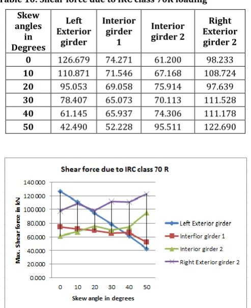
[image:5.595.310.557.374.677.2]Shear force
Table 10: Shear force due to IRC class 70R loading Skew
angles in Degrees
Left Exterior
girder
Interior girder
1
Interior girder 2
Right Exterior girder 2 0 126.679 74.271 61.200 98.233 10 110.871 71.546 67.168 108.724 20 95.053 69.058 75.914 97.639 30 78.407 65.073 70.113 111.528 40 61.145 65.937 74.306 111.178 50 42.490 52.228 95.511 122.690
Figure 12: skew angle vs live load shear force
[image:5.595.37.279.623.750.2]© 2016, IRJET | Impact Factor value: 4.45 | ISO 9001:2008 Certified Journal
| Page 182
Torsion
Table11: Torsion due to IRC class 70R loading
Skew angles
in Degrees
Left Exterior
girder
Interior girder
1
Interior girder
2
Right Exterior girder 2 0 34.211 67.014 111.575 60.936 10 31.742 67.064 106.021 60.857 20 27.699 66.026 114.212 63.324 30 34.865 66.627 110.592 50.945 40 31.759 84.885 137.800 41.207 50 60.710 84.082 147.514 44.523
Figure 12: skew angle vs live load torsion
The torsion maximum at 500 skew bridge for interior girder 1, 2 and left exterior girder. It is observed that the torsion is will increase for large skew angles. The interior girder 2 is carrying more torsion in bridge for IRC class 70R loading.
6. CONCLUSIONS
Based on the analysis results of different skewed bridges, the following conclusions can be made;
1) The bending moment for dead load case, with increase in skew angle there is uniform decrease in the bending moment, about 14% of bending moment is decreases. 2) For the case of IRC class A loading and class 70R loading,
the bending moment decreasing with the increase in skew angle. About 17% for class A loading and about 25% for class 70R loading bending moment decreases. 3) In case of dead load the shear force is increased in small
amount about 0.2% with increase in skew angle. 4) For live load case also the shear force is varying with
respect to skew angle. About 25% shear force increased for class A loading and about 22% shear force is decreasing for class 70R loading.
5) Torsion is about 68% increased due to increase in skew for class A loading and about 33% decreases for class 70R loading.
7. SCOPE FOR FURTHER STUDY
1) This study is conducted by considering single span simply supported Steel I-girder Bridge, further the study can be made on multiple spans using I- girder or U- girder with cast-in-situ deck slab.
2) In this study effect of seismic and wind are not considered, therefore inclusion of seismic and wind effect (Dynamic effect) can be taken up as the research or study topic.
REFERENCES
[1] Ansuman kar, Vikash Khatri, P.R. Maiti, P. K. Singh (2012) “ Study on Effect of skew angle in skew bridges”, International Journal of Engineering Research and Development, Vol 2, pp. 13-18
[2] Gholamreza Nouri, Zahed Ahmadi (2012), “Infuence of Skeew Angle on Continuous Composite Girder Bridge”, ASCE library visheshwaraya Technological University, Belgaum, pp. 617-623
[3] Himanshu Jaggerwal, Yogesh Bajpai (2014), “ Effect of Skewness On Three span Reinforced Concrete T Girder Bridges”, International Journal of Computational Engineering Research, vol 4, pp. 2250-3005
[4] M. Ameerutheen, Aravindan (2014). “Study of Stresses on Composite Girder Bridge Over Square and Skew Span”, International Journal of Civil Engineering and Technology, Vol 5, pp 88-96
[5] Nikhil V. Deshmukh. U. P. Waghe (2015), “ Analysis and Design of Skew Bridges”, International Journal of Science and Research, vol 4, pp. 399-402
[6] Patrick Theoret, Bruno Massicotte, David Concistori (2012), “ Analysis and Design of Straight and Skewed Slab Bridges”, Journal of Bridge Engineering, pp 289-301
[7] Sindhu B. V, Ashwin K. N, Dattatreya J. K., S. V. Dinesh (2013), “ Effect of Skew Angle on Static Behaviour of Reinforced Concrete Slab Bridge Decks.
[8] Sujih P. S, Jiji Anna varughese, Tennu Syriac (2015), “ Comparative Study on the Behaviour of T- Beam Skew Bridge”, Internation journal of Innovative Research in Science, Vol 4, pp. 8287-8295
© 2016, IRJET | Impact Factor value: 4.45 | ISO 9001:2008 Certified Journal
| Page 183
BIBLIOGRAPHY
[1] Mahmoud Sayed-Ahmedc, Khaled Sennah (2013). “Finite Element and Model Analysis of 3D Jointless Skewed RC Box Girder Bridge’, Concrete Research Letters, vol 4, pp. 557-568
[2] Ankit Gupta, Diwakar prakash Verma, Jagdish Singh Dasouni, Girija Shanker,() “Suitability of POT/PTFE Bearing in Bridges”, International Journal of Current Research and Academic Review, vol 2, pp 47-53
[3] Gokhan Pekan, Ahmed Abdel-Mohti (2008) “Seismic Response of Skewed RC Box-Girder Bridges”, The 14th World Conference on Earthquake Engineering.
[4] P. Pattatheere, P. Renault (2008), “Seismic Vulnerability Assessment of Skew Bridges”, The 14th World Conference on Earthquake Engineering.
BIOGRAPHIES
MANJUNATH K
M.Tech (CADS),
Department of Civil Engineering, University B D T College of Engineering Davangere-577004.
Dr. H R PRABHAKARA
Professor,
Department of Civil Engineering, University B D T College of Engineering Davangere-577004.
Dr. MAHADEV M ACHAR
Senior Vice President, Transys Consulting Pvt Ltd, Bangalore-560001.