doi:10.4236/wjm.2011.12004 Published Online April 2011 (http://www.SciRP.org/journal/wjm)
Nonlinear Dynamic Characteristics of a Simple Blade with
Breathing Crack Using Ansys Software
Salwan Obeed Waheed, Nawras Haidar Mostafa, Dhyai Hassan Jawad
Mechanical Engineering Department, University of Babylon, Hilla, Iraq E-mail: bn.bn18@yahoo.com, nawras1980@gmail.com, dh_1970@yahoo.com
Received March 1, 2011; revised March 30, 2011; accepted April 2, 2011
Abstract
Nonlinear dynamic response represents the most important studies for structures subjected to a dynamic mo-tion so that it provides the researcher by an excellent informamo-tion especially at critical design levels. The un-predictable nonlinearity in the structure appears when damage is inherited. Most times, the failure of the structure is related to the dynamic nonlinearity. With regard to the breathing phenomena for nonlinear struc-tural systems, very little is known about how the nonlinearities influence the response and the dynamic char-acteristics of cracked structures. In this research, dynamic nonlinearity is presented in damaged structure due to presence of a crack. The crack is assumed to be open and close simultaneously and then breathing. Effect of breathing phenomenon was studied deeply. Crack breathing is simulated at the crack surfaces using con-tact elements. The concon-tact, geometrical, penalty, and spin stiffnesses are taken in consideration. In addition, effect of several important parameters such as rotor angular velocity and crack ratio are studied. The study showed that the breathing natural frequency of any structure is ranged between opened (no contact) and closed crack natural frequencies. The larger crack length is, the more nonlinear disturbance in the dynamic response behavior. Also, at a critical crack length, some mode shapes tend to exchange and pass over with other modes. The presence of the mode interchanging and mode crossover was a guide on the nonlinear re-sponse for the cracked structure. The numerical modeling is achieved using ANSYS finite element program. Experimental data are used for validating the accurate use of contact elements in ANSYS environment.
Keywords: Nonlinear Dynamics, Breathing Phenomena, Cracked Blade, Contact, ANSYS
1. Introduction
A crack, one of the most common defects in a structure, may result in a dangerous effect on the dynamic behavior of structures. It may lead to improper structural per-formance, which can eventually destroy the structure. Generally, a crack induces changes in the structure's stiffness, and also reduces the frequency of the structure. The vibration of cracked structures has attracted consid-erable interest from many researchers due to its practical importance and the numerous issues that arise in the context of linear and nonlinear dynamics theories. The dynamic characteristics of a cracked structure and an intact structure are different in principle. The reason for this difference is the change in stiffness when a structure is cracked. During vibration, a crack will open and close in time due to an externally applied loading. This phe-nomenon is known as the breathing process of the crack.
ways the relationship between the crack characteristics, localization and depth, and the vibration properties of the mechanical element [2].
In the early stages of this area of study, most investi-gations used an assumption that the cracks of the struc-tures are always open, and thus contact between the crack surfaces does not occur. It is convenient to assume that the crack is always open because the system remains linear. However, this assumption is not accurate in many cases. For example, for structures with fatigue-induced cracks, the gaps between the crack surfaces are very small, and the closing of the crack surfaces occurs in reality [3]. Furthermore, if the cracked structure is a ro-tating machinery component, such as a blade disk in a turbine engine rotor, then considering the effects of rota-tion on the nonlinear vibrarota-tion response is important. An extensive literature survey regarding research activities on rotating beams was provided by [4]. It should be noted that the change in the rotating equilibrium con-figuration due to the inertial loading is of particular in-terest for the vibration analysis of cracked structures. The initial gap between the crack surfaces can change sig-nificantly with increasing rotation speed. Some structures, such as turbine blades, propellers, satellites, etc., rotate while in operation and the rotating speeds are constant for many applications. The dynamic characteristics of rotating elastic bodies are different from their dynamic characteristics in the nonrotating state. The difference is come from the centrifugal force which causes to change in the stiffness of the body by an amount which is called the “apparent stiffness” by Hurty and Rubinstein in 1964 or called sometimes “geometric stiffness” described by Likins in 1974 as mentioned in the paper published by [5].
For the study of cracked Bernoulli–Euler beams, a pio-neering contribution was made by [6] in their application of the Hu–Washizu–Barr variational principle to the cracked beam problem. Further extension was made by [7] for Bernoulli–Euler beams with symmetric cracks and single-edge cracks [8]. A generalization to the theory was made by [9]. However, in these studies, the nonlin-ear effect was not considered. Reference [10] pointed out that measured natural frequencies of a beam with a fa-tigue crack differ from those calculated without consid-ering the crack closing effect. He also addressed the sig-nificance of the crack closing effect for accurately pre-dicting the frequency shifts due to cracking. Reference [11] considered the vibration response of a beam with breathing crack. A cantilever beam was used and mod-eled as a one-degree-of-freedom lumped parameter sys-tem. This simplified model simulates the beam vibrating at its first mode. They incorporated the breathing crack model into a single-degree-of-freedom system as a
har-monic change in the beam stiffness. Their analysis showed that the natural frequency reduction for a fatigue crack (breathing crack) was much smaller than that for an open crack.
23
One of the most important goals in the present search is to better understanding why the difference between the results for same breathing modeling. To accomplish this, an experimental and theoretical investigation to the nonlinear behaviors of a cracked structure is proposed. Effects of rotation with breathing phenomenon together were also investigated. A finite element method is used to analyze the nonlinear vibration of a rotating blade with a crack. In particular, the solution of the forced vibration of a cracked rotor blade made from Ti-6Al-4V is inves-tigated. The breathing effect of the crack, the effects of rotation, and crack ratio are considered in this study.
2. Finite Element Discretization
The finite element method is the most powerful numeri-cal technique, which offers an approximate solution to most realistic types of structures. The use of the compu-tational tools becomes common in design, and the need for explicit design formulas have therefore decreased. More direct and accurate calculations may be performed in order to achieve safe and optimal design. Here, AN-SYS is used to analyze the rotor blade.
2.1. Element Parameters
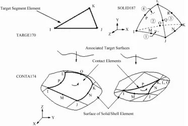
SOLID187 element is a higher order 3-D, 10-node ele-ment is used to mesh the blade. SOLID187 has a quad-ratic displacement behavior and is well suited to model-ing irregular meshes. TARGE170 is used to represent
various 3-D “target” surfaces for the associated contact elements. CONTA174 is used to represent contact and sliding between 3-D “target” surfaces (TARGE170) and a deformable surface, defined by this element. The ele-ment is applicable to 3-D structural and coupled field contact analyses. This element is located on the surfaces of 3-D solid or shell elements with mid side nodes (SOLID187). It has the same geometric characteristics as the solid or shell element face with which it is connected. Contact occurs when the element surface penetrates one of the target segment elements (TARGE170) on a speci-fied target surface. The coordinate system for these ele-ments are shown in Figure 1.
2.2. Blade Geometry and Mesh Generation
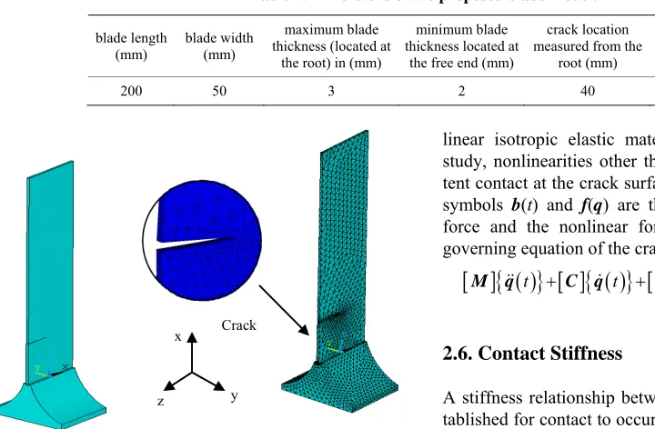
The blade is discretized using solid element (solid187). ANSYS finite element program was used as a mathe-matical tool in the analysis of this model. Figure 2 shows the finite element representation of the blade structure. It must be noted that, the number of the ele-ments in the crack location must be sufficient to give the required accuracy and controlling the dramatic changes that occurs at the crack location. Therefore, some con-vergence studies should be induced to obtain the required numbers of element for covering the mesh processes. After these studies, it was noted that the element number should be not less than 6350 elements for the blade ge-ometry.
[image:3.595.114.487.453.704.2]All dimensions of the blade are listed in Table 1 below.
Table 1. Dimensions of the proposed blade model. blade length (mm) blade width (mm) maximum blade thickness (located at
the root) in (mm)
minimum blade thickness located at
the free end (mm)
crack location measured from the
root (mm)
rotor diameter (mm)
200 50 3 2 40 400
Crack x
y z
Figure 2. Blade configuration and mesh generation.
2.3. Strain Displacement Relation
The strain-displacement relationship can be written with its dependence explicitly expressed as, [18].
B q (1)where
is Strain vector,
B is strain-displacementmatrix and
q is the Nodal displacement vector.All elements of strain–displacement matrix are derived in terms of the shape function derivatives and the Jaco-bian matrix.
2.4. Element Stiffness and Mass Matrices
In general, the basic concept of the finite elements method is to discrete the continuum into a definite numbers of small elements connected together at their common nodes. Depending on the strain-displacement matrix,
B , theelement stiffness
K and element mass
Mmatri-ces can be written as; [18],
T dV V
K B E B (2)
T dV V
M N N (3) where
E is stress-strain matrix,
N is the shape func-tion matrix, V is the volume and ρ is the mass density.
2.5. Dynamic Governing Equilibrium Equation
In this paper, the vibration of a rotor blade composed of
linear isotropic elastic material is considered. In this study, nonlinearities other than the one due to intermit-tent contact at the crack surfaces are not considered. The symbols b(t) and f(q) are the time dependent external force and the nonlinear force respectively. Thus, the governing equation of the cracked blade is [19]
M
q
t
C
q
t
K
q
t
b
t
f q
(4)2.6. Contact Stiffness
A stiffness relationship between two bodies must be es-tablished for contact to occur. Without a contact stiffness, bodies will pass through one another. The relationship is generated through an elastic spring that is put between the two bodies, where the contact force is equal to the product of the contact stiffness (kc) and the penetration (δ). The amount of penetration (δ), or incompatibility, between the two bodies is therefore dependent on the stiffness kc. Ideally, there should be no penetration, but this implies that kc = infinity, which will lead to numeri-cal instabilities. The value of kc that is used depends on the relative stiffness of the bodies in contact. The contact stiffness is determined by the following relationships [20]:
2 0c
k fs A K Vm 0 (5)
where Km is the bulk modulus of contacted element, A0 is the area of contact segments, V0 is thevolume between contacted segments and fs is the penalty factor.
3. Experiment Test Validation
25
frequency as depicted in Figure 3.
The presence of a crack in the beam, according to the principle of Saint-Venant, causes a perturbation of the stress field in the neighborhood of the breach. Such a perturbation is relevant especially when the crack is open and determines a local reduction of the flexural rigidity. On the other hand, when the crack is closed the beam
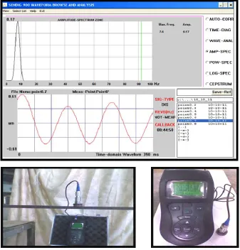
[image:5.595.128.465.176.528.2]acts, approximately, as a homogeneous beam with no crack [21]. Three cases of cantilevered beam is tested namely a beam without crack, a beam with open crack, and a beam with breathing crack. Table 2 lists the beam geometry and crack dimensions. While, Table 3 lists the given experimental data and the corresponding ANSYS results.
Figure 3. Tested data and vibration kit.
Table 2. Dimensions of tested beam.
Effective beam length (m)
Beam cross-section area
[image:5.595.129.469.643.721.2](m2) Location of the crack from the beam fixed end (m) Crack depth (m) 0.93 (9*10-3)* (9*10-3) 0.05 5*10-3
Table 3. Experiment versus finite element results.
Natural frequency of the beam (Hz) Case
Experimental ANSYS results Uncracked beam (closed crack) 8.53 8.57
The beam with breathing crack (nonlinear) 7.60 7.71 The beam with open crack (linear) 7.20 7.25
As can be seen, the nonlinear systems have higher reso-nant frequencies than the linear systems and breathing frequency lies between the uncracked (or closed crack) and opened crack natural frequencies. This indicates that the compliance of the linear system is greater than that for the nonlinear systems, which makes sense because penetration of the crack surfaces is allowed for the linear case.
4. Results and Discussion
Table 4 lists the mode shapes and corresponding crack ratios. The modes of interest being third, fourth, fifth, and sixth because these modes represent the in plane and out plane deformed shapes of the structure.
It is very clear that the presence of the crack has a great effect on the modes of deformation as shown in Figure 4. The increasing of crack ratio (crack length/ blade width) from 0 to 0.2 exhibits no effect on the mode shape but an increasing in the amplitude of the deforma-tion will occur. At a crack ratio of 0.4, an exchange in the mode shapes occurs, so that the 5th mode will veering to the 4th mode and then transform from sin bending mode to in plane one (breathing crack).
In other words, the 4th mode is transferred to the 5th one at 0.4 crack ratio which means a reduction in the overall stiffness due to the increasing the crack ratio. The transformation between modes means that there is a re-duction or lack in the stiffness (local stiffness) that in turn leads to change in the overall stiffness. These trans-formations between modes, due to the changes in crack ratios, give an excellent imagination that what the crack can do. The changing in several modes and no changing in the others for a specific crack ratio means that there is a critical crack length just at which the mode interactions phenomenon are occurred [3].
4.1. Effect of Crack Ratio on Time and Frequency Domains
In the time domain, the amplitude history with time was showed. The more important is to obtain the eigen modes for both linear and nonlinear crack models. Therefore, the frequency domain is constructed using FFT (Fast
Fourier Transform). The comparison of the frequency domain is fulfilled between linear and nonlinear cracked models.
If one creates a FE model with a crack and performs forced response analysis or modal analysis without con-sidering the crack-closing effect, then the response is linear (penalty stiffness is not existed on the crack sur-faces). This modeling approach does not preserve cyclic symmetry in the geometry of the tuned system, but it does yield a linear system. This approach is referred to linear cracked blade model. The nonlinear cracked blade model is the cracked blade model where the intermittent contact of the crack surfaces during the vibration is fully considered.
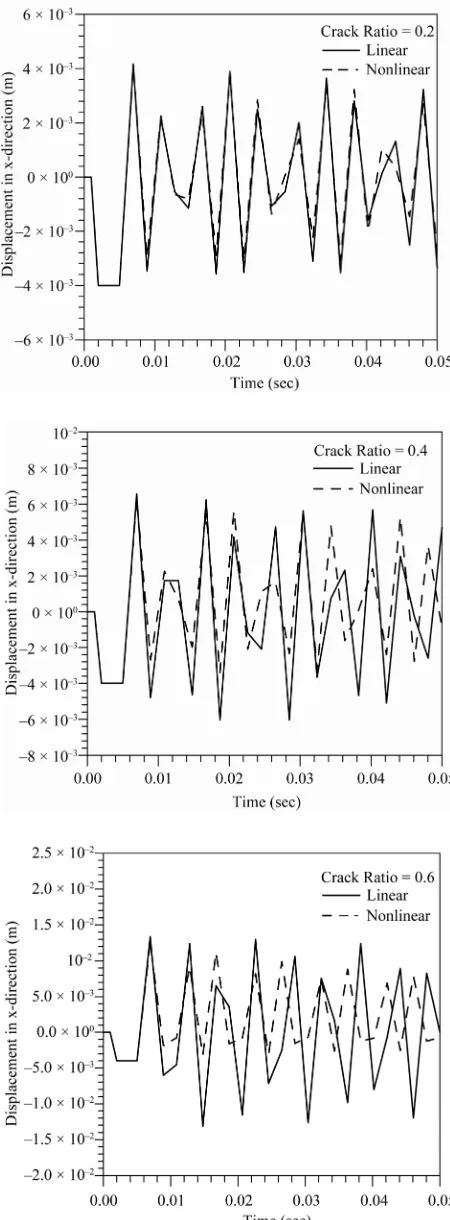
The frequency domain gives a good explanation about the frequency at maximum response amplitude. Figure 5 presents the time responses for linear (open crack, no contact) and nonlinear (breathing crack, with contact) vibrations, the breathing effect is very clear when its compared with linear mode.
[image:6.595.309.537.415.593.2]In the other hand, the displacement of nonlinear re-sponse in the negative direction (the direction that leads to converge the crack surfaces) is smaller than open crack displacement. This is a good indication about the effect of penalty stiffness (compression spring element) which resulted from crack surface impact. To distinct the eigen frequency, Figure 6 is conducted in frequency
[image:6.595.111.482.636.719.2]Figure 4. Modes veering and transformation.
Table 4. Present crack ratios and corresponding mode shapes.
Crack ratio 3rd mode 4th mode 5th mode 6th mode 0 simple torsion sin bending in plane bending complex torsion and bending 0.2 simple torsion sin bending in plane bending complex torsion and bending
0.4 simple torsion in plane bending sin bending complex torsion and bending 0.6 simple torsion in plane bending sin bending complex torsion and bending
27
[image:7.595.313.538.77.689.2][image:7.595.57.282.79.689.2]
Figure 5. Tip end displacement with time of cracked blade with different crack ratios.
domain. As can be seen, the frequency response function predicted by the linear cracked blade does not match that predicted by the nonlinear cracked blade model.
The most notable distinction between the results from the linear model and the nonlinear model is that the resonant frequencies of the cracked-blade dominated response shifts significantly toward higher frequencies for the nonlinear case. This effect is due to the intermit-tent contact at crack surfaces, the so-called closing or breathing crack effect. Namely, the stiffness of the cracked blade is underestimated by the linear model that neglect contact and so are the resonant frequencies.
Generally, the distinctions between linear and nonlin-ear frequencies and amplitudes are increased with the increasing the crack ratio due to the combined effects of mass and stiffness of the cracked structure (reduction in the stiffness because of the mass discontinuity).
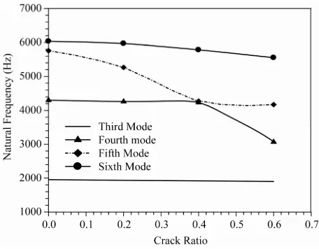
4.2. Effect of Rotating Velocity and Crack Ratio
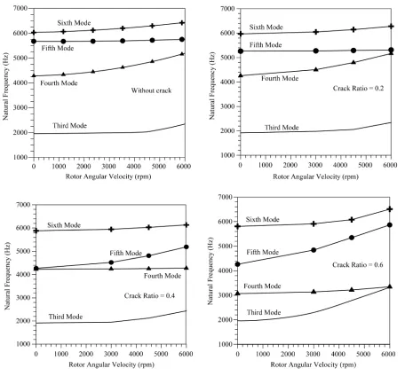
The effect of rotating velocity on the natural frequencies of the blade is shown in Figure 7. It is obvious that the blade natural frequencies are increased with increasing the rotor velocity for all selected modes. This event is caused by increasing the centrifugal force that in turn leads to increase the stress stiffening (spinning stiffness). It should be pointed that the increasing frequency band-width is different from mode to another. There are little changes in the blade frequencies for the in-plane bending modes (5, 5, 4 and 4 for crack ratios 0, 0.2, 0.4, and 0.6 respectively) when they compared with other modes. The main reason for this little change is that the rotating ve-locity provides a centrifugal force leads by the way to create a reversed moment load tends to re-back the blade to its equilibrium shape. However, the blade deformation
[image:8.595.73.529.289.713.2]
29
at resonant frequency for the in-plane mode is smaller than other bending modes. Thus, the rotational velocity has no significant effects on the blade dynamic charac-teristics.
It is important to clear that a reversed moment is the product of multiplying the centrifugal force by the in-stantaneous distance between the deformed center at resonant frequency and the equilibrium blade mass cen-ter. The other bending modes (4, 4, 5 and 5 for crack ratios 0, 0.2, 0.4 and 0.6 respectively) seem to be the most affected one, because these modes having out of plane nature at the resonant frequencies (sin wave) and the centrifugal force produces a reversed moment.
5. Conclusions
The following conclusions can be deduced from this study as:
1) The presence of the crack in the structure does not change all modes shapes but there are critical crack lengths for each mode lead to interchanging between them.
2) The increasing in the natural frequency with the in-creasing in the angular velocity in the presence of the crack means that the effect of the crack is decreased with increasing the velocity.
3) Increasing crack ratio lead to increase the structure time response, i.e. increasing nonlinearity.
4) Breathing crack natural frequency lies between open crack and closed crack natural frequencies of that structure.
5) The presence of the mode interchanging and mode crossover is a guide on the nonlinear response for the cracked structure.
6. References
[1] V. Khoa and O. Olatunbosun, “A Method for Remote Monitoring of Structural Health Based on the Nonlinear Phenomenon in Dynamic Response of Damaged Struc-tures,” Proceedings of the World Congress on Engineer-ing, London, 2-4 July2007.
[2] S. Benfratellol, P. Cacciola, N. Impollonia, A. Masnata and G. Muscolino, “Crack Identification in a Beam by Measure of the Response to White Noise,” Computers & Structures, Vol. 81, No. 18-19, 2006, pp. 1773-1782. [3] A. Saito, M. P. Castanier and C. Pierre, “Estimation and
Veering Analysis of Nonlinear Resonant Frequencies of Cracked Plates,” Journal of Sound and Vibration, Vol. 326, No. 3-5, 2009, pp. 725-739.
[4] A. Bazoune, “Survey on Modal Frequencies of Centri-fugally Stiffened Beams,” The Shock and Vibration Di-gest, Vol. 37, No. 6, 2005, pp. 449-469.
doi:10.1177/0583102405056752
[5] Y. Chou and W. Yeh, “Prediction of Rotating Blade Modes from Measured Non-Rotating Modal Parameters,”
Journal of Vibration and Acoustics, Vol. 113, No. 4, Oc-tober 1991, pp. 423-557.
[6] S. Christides and A. Barr, “One-Dimensional Theory of Cracked Bernoulli–EULER Beams,” International Jour-nal of Mechanical Sciences, Vol. 26, No. 11-12, 1984, pp. 639-648. doi:10.1016/0020-7403(84)90017-1
[7] M. Shen and C. Pierre, “Natural Modes of Bernoulli– Euler Beams with Symmetric Cracks,” Journal of Sound and Vibration, Vol. 138, No. 1, 1990, pp. 115-134. doi:10.1016/0022-460X(90)90707-7
[8] M. Shen and C. Pierre, “Free Vibrations of Beams with a Single-Edge Crack,” Journal of Sound and Vibration, Vol. 170, No. 2, 1994, pp. 237-259.
doi:10.1006/jsvi.1994.1058
[9] T. G. Chondros, A. D. Dimarogonas and J. Yao, “A Con-tinuous Cracked Beam Vibration Theory,” Journal of Sound and Vibration, Vol. 215, No. 1, 1998, pp. 17-34. doi:10.1006/jsvi.1998.1640
[10] P. Gudmundson, “The Dynamic Behavior of Slender Structures with Cross-Sectional Cracks,” Journal of the Mechanics and Physics of Solids, Vol. 31, No. 4, 1983, pp. 329-345. doi:10.1016/0022-5096(83)90003-0
[11] S. M. Cheng, A. S. Swamidas, X. J. Wu and W. Wallace, “Vibrational Response of a Beam with a Breathing Crack,” Journal of Sound and Vibration, Vol. 225, No. 1, 1999, pp. 201-208. doi:10.1006/jsvi.1999.2275
[12] W. L. Bayissa and N. Haritos, “Experimental Investiga-tion into VibraInvestiga-tion Characteristics of a Cracked RCT- Beam,” Melbourne University Private Ltd Report, 2006. [13] S. S. Ki and J. H. Kim, “Rotating Composite Beam with a
Breathing Crack,” Composite Structure, Vol. 60, No. 1, 2003, pp. 83-90.
[14] T. G. Chondros, A. D. Dimarogonas and J. Yao, “Vibra-tion of a Beam with a Breathing Crack,” Journal of Sound and vibration, Vol. 239, No. 1, 2001, pp. 57-67. doi:10.1006/jsvi.2000.3156
[15] X. S. Andreas and A. Polycarpou, “Measurement and Modeling of Normal Contact Stiffness and Contact Damping at the Meso Scale,” ASME Transactions of the ASME, Vol. 127, February 2005.
[16] C. C. Ma and C. H. Huang, “Experimental and Numerical Analysis of Vibrating Cracked Plates at Resonant Fre-quencies,” Experimental Mechanics, Vol. 41, No. 1, 2001, pp. 8-18. doi:10.1007/BF02323099
[17] M. Kulyk, O. Kucher, V. Kharyton, J. Laine and F. Thouverez, “Dynamic Nonlinear Analysis of Cracked Blade,” Journal of Aviation, Vol. 12, No. 3, 2008, pp. 66-79.doi:10.3846/1648-7788.2008.12.66-79
[18] S. S. Rao, “The Finite Element Method in Engineering,” Fourth Edition, Elsevier Science & Technology Books, 2004.
2009, pp. 011005.
[20] ANSYS, “Engineering Analysis System Theoretical Manual,” http://www. Ansys. Com. Ansys, Version 11, 2007.
[21] P. Cacciola, N. Impollonia and G. Muscolino, “Crack
Detection and Location in a Damaged Beam Vibrating under White Noise,” Computers & Structures, Vol. 81, No. 18-19, 2003, pp. 1773-1782.