THE BA-PB-O SYSTEM AND ITS POTENTIAL AS A SOLID OXIDE FUEL CELL (SOFC) CATHODE MATERIAL
Matthew David Sharp
A Thesis Submitted for the Degree of MPhil
at the
University of St. Andrews
2007
Full metadata for this item is available in Research@StAndrews:FullText
at:
http://research-repository.st-andrews.ac.uk/
Please use this identifier to cite or link to this item: http://hdl.handle.net/10023/378
This item is protected by original copyright
The Ba-Pb-O System and its
Potential as a Solid Oxide Fuel Cell (SOFC)
Cathode Material
A thesis presented for examination for the title of M.Phil.
by
Matthew David Sharp
University of St Andrews
Declaration
I, Matthew David Sharp, hereby certify that this thesis, which is approximately 25, 000 words in length, has been written by me, that it is the record of work carried out by me and that it has not been submitted in any previous application for a higher degree.
Date: Signature of Candidate:
I was admitted as a research student in February 2004 year and as a candidate for the degree of Master of Philosophy in February 2007; the higher study for which this is a record was carried out in the University of St Andrews between 2004 and 2007.
Date: Signature of Candidate:
I hereby certify that the candidate has fulfilled the conditions of the Resolution and Regulations appropriate for the degree of Master of Philosophy in the University of St Andrews and that the candidate is qualified to submit this thesis in application for that degree.
Date: Signature of Supervisor:
In submitting this thesis to the University of St Andrews I understand that I am giving permission for it to be made available for use in accordance with the regulations of the University Library for the time being in force, subject to any copyright vested in the work not being affected thereby. I also understand that the title and abstract will be published, and that a copy of the work may be made and supplied to any bona fide library or research worker.
Acknowledgements
To all those and all things that have helped me on my way . . .
Firstly, I would like to thank my supervisor, John Irvine, who suggested and guided the project, introducing me to the world of fuel cells in the process. It is difficult to imagine a better supervisor than John, with his infinite support and excellent advice, regarding work and also the shortcomings of any England team following a game with Ireland!
A special mention goes to my parents and brother for their never faltering support, love and encouragement in everything I do. Perhaps now I may enter the real world of work!
To Angela Kruth for getting me started with barium plumbates and for help with X-ray diffraction.
Much gratitude goes go to Maarten Verbracken and Christian Savaniu for assistance with A.C. impedance spectroscopy and sol-gel processing, respectively.
Paul – thanks for sticking by me and answering every question I’ve fired in your general direction.
My thanks also go to all those in the workshop who have assisted me during the course of the project, especially George; thanks for all those insightful conversations on the subject of plants and gardening.
Thank you Sneh for being my acting mother figure for all the time I’ve known you, and for all those fine meals.
And what would St Andrews life be like without the existence of the Aikman’s music quiz? To all those gregarious times, to the beer, much music trivia and to winning the music quiz! As usual, it is the people who always make the occasion: Maarten, Davo, Fran, Kelcey, Rachel and the two physicists, Dave and Chris. You will all be missed.
Abstract
The Ba-Pb-O system was investigated as a possible cathode material in a solid oxide fuel cell (SOFC). Metallic oxides with a perovskite structure form a large family that displays a wide variety of properties such as superconductivity, ferroelectricity and
catalysis. Barium plumbates have been studied extensively in recent years because of such interesting properties. BaPbO3 is known to exhibit room temperature metallic
conductivity, due to an overlap (~2 eV) of the O2p nonbonding band with the Pb-O sp
antibonding band at the Fermi level. Another phase in the Ba-Pb-O system, Ba2PbO4, is
known to adopt the K2NiF4 structure and behaves as a large-gap semiconductor (valence
bands are separated by a ∼1.7 eV semiconductor gap).
The compounds BaPbO3 and Ba2PbO4 have been prepared with a view to
evaluating them as fuel cell materials, in terms of compatibility with common electrolytes such as YSZ and CGO, stability under fuel cell operating conditions, and
overall performance. The effect of substituting Y and Sc in the structures has also been studied using a combination of XRD and A. C. impedance spectroscopy.
It was found that BaPbO3 offers good performance compared with
La0.8Sr0.2MnO3-x (LSM) and La0.6Ca0.4MnO3-x (LCM) in the lower temperature region
for SOFC operation (700 – 800 K), giving an activation energy of 0.93 eV. The introduction of Y to the BaPbO3 structure reduced performance.
Electrode/electrolyte compatibility studies revealed BaPbO3 and YSZ or CGO to
be unstable to 800 °C – the formation of cerate or zirconate phases was observed. No
use with BaPbO3 since CGO offers good performance at temperatures where the
electrode is stable.
In order to avoid high sintering temperatures for electrode adhesion, BaPbO3
precursors were impregnated into porous CGO, before firing at 700 °C, thus creating a
Contents
Section
Page number
Chapter 1: Introduction 1
1.1 Preamble 1
1.2 Fuel Cells 2
1.2.1 Thermodynamics 2
1.2.2 Introduction – Basic Principles of the Fuel Cell 5
1.2.3 Types of Fuel Cell 7
1.2.4 Materials for SOFCs 9
1.2.5 Electrolytes for SOFCs 10
1.2.6 Anodes for SOFCs 10
1.2.7 Cathodes for SOFCs 11
1.2.8 Functionally Graded Composite Cathodes 12
1.2.9 Interconnects for SOFCs 17
1.2.10 Cell Design and Fabrication 17
1.2.11 Applications 21
1.2.12 Environmental Issues 22
1.2.13 Summary 24
1.3 The Chemistry of Common SOFC Electrolytes 24
1.3.1 Yttria-Stabilised Zirconia (YSZ) 24
1.3.2 Aliovalent Doping 27
1.3.3 Ionic Conductivity 30
1.3.4 Ceria (CeO2)-based and other SOFC Electrolytes 32
1.4 Oxygen Deficiency in Perovskites 34
1.5 Conductivity 35
1.5.1 Electronic Conductivity 35
1.5.2 Semiconductivity 38
1.6 The Perovskite Structure, ABX3 40
1.7 The Ruddleston-Popper Structure (K2NiF4) 42
1.8 The Structure and Properties of Compounds in the
Ban+1PbnO3n+1Series 44
1.8.1 Introduction 44
1.8.2 BaPbO3(n =∞) 45
1.8.3 Ba2PbO4(n = 1) 50
1.9 Summary and Aims 51
1.10 References 51
Chapter 2: Experimental 56
2.1 Structure of Chapter 56
2.2 Synthetic Experimental Procedures 56
2.2.1 Powder Preparation 56
2.2.1.2 Preparation of Barium Plumbates and Doped
Barium Plumbates 58
2.2.2 Pellet Preparation 58
2.2.3 Preparation of Inks for Screen Printing and
Vacuum Impregnation 59
2.2.4 Screen Printing 59
2.2.5 Composite Cathode Fabrication 60
2.2.5.1 Pellet Co-pressing with carbon Pore-formers;
Creating a Layered CGO Matrix 61
2.2.5.2 Vacuum Impregnation 62
2.3 Experimental Techniques 65
2.3.1 X-ray Diffraction (XRD) 65
2.3.2 Scanning Electron Microscopy (SEM) 69
2.3.3 Energy Dispersive X-ray Spectroscopy (EDS) 72
2.3.4 Optical Microscopy 74
2.3.5 Examination of the Presence of Barium Cerate/Zirconate
Phases; Electrolyte Compatibility Studies 75
2.3.6 Material Stability Testing 76
2.3.7 Thermal Analysis 76
2.3.8 A.C. Impedance Spectroscopy 77
2.3.8.1 Theory 77
2.3.8.2 Equivalent Circuits 80
2.3.8.3 Experimental 84
2.3.8.4 Sample Geometry Correction 85
2.3.8.5 Activation Energy 88
2.4 References 89
Chapter 3: Results & Discussion 90
3.1 Plumbate and Doped Plumbate Characterisation 90
3.1.1 X-ray Diffraction (XRD) 90
3.1.2 Scanning Electron Microscopy (SEM) 93
3.1.3 Energy Dispersive X-ray Spectroscopy (EDS) 94
3.2 Material Stability Testing 94
3.3 Thermal Analysis 97
3.4 Electrolytes 98
3.5 Initial Electrochemical Studies – Symmetrical Cells 100
3.5.1 BaPbO3Symmetrical Cell 100
3.5.2 BaPb0.9Y0.1O3-xSymmetrical Cell 103
3.6 Examination of the Presence of Barium Cerate/Zirconate
Phases; Electrolyte Compatibility Studies 105
3.7 Composite Cathode 109
3.7.1 Optical Microscopy 111
3.7.2 Scanning Electron Microscopy (SEM) 112
3.7.3 Energy Dispersive X-ray Spectroscopy (EDS) 117
3.7.4 A.C. Impedance Spectroscopy 118
3.7.4.1 Layered CGO Matrix 118
3.7.4.2 BaPbO3-Impregnated 119
Chapter 4: Conclusions 124
4.1 Conclusions 124
4.2 Suggestions for Future Work 126
Chapter 1
Introduction
1.1 Preamble
There is currently considerable debate as to the future roles of renewable and nuclear electricity generation. Renewables seem unable to offer robust large-scale
implementation; however in combination with fuel cells a robust decentralised energy generation system could be created.
Of the many types of fuel cell available, the solid oxide fuel cell (SOFC) has shown great promise for a wide variety of applications, from portable 1 kW devices to
larger 100+ kW plants pursued by such companies as Siemens Westinghouse. SOFCs are advantageous as they use a solid, chemically stable electrolyte, which eliminates
corrosion and leakage. Heat, a useful by-product, may also be used for the co-generation of energy.
The recent focus on development of solid oxide fuel cells (SOFCs) has been to reduce their operating temperature, allowing the use of less expensive materials for use
1.2 Fuel Cells
1.2.1 Thermodynamics
Sir William Grove (1811 – 1896), a British Chemist, produced a gas battery -
the first working fuel cell- which was first reported in 1839[1]. A fuel cell is an electrochemical energy conversion device, where chemical energy in the supplied fuel, with addition of an oxidant, effects a change to electrical energy in a direct fashion; any
intermediate combustion steps are negated e.g. as opposed to the internal combustion engine. This is accentuated below (Figure 1.1).
Figure 1.1: (a) Conventional means of power generation, (b) Power generation by means of fuel cells.
Conventional means of power generation such as the cyclic heat engine i.e. a
steam engine or an internal combustion engine are subject to the Carnot limitation, where the efficiency of an engine, , is given by Equation 1.1:
1 2 1
T T T − =
η (Equation 1.1)
Chemical Energy
Chemical
Energy Electrical Energy
Heat
Energy Mechanical Energy Electrical Energy
(a)
Where:
η = The efficiency of the process.
T1 =The temperature of the combustion process in going from chemical to heat energy.
T2 = The temperature of the heat sink (the environment to which the combustion
products are exhausted).
The internal combustion engine takes energy from a hot reservoir (the burning fuel) and uses it to do work. However, for the second law of thermodynamics to be
obeyed, T2 ≠ 0; heat which cannot be used to do work is exhausted. The variation in
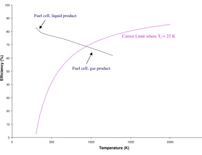
efficiency with temperature of a Carnot-limited system is shown in Figure 1.2.
Fuel cells are exempt from the Carnot limitation since they use a process, which goes directly from chemical to electrical energy (Figure 1.1). H of the reaction is used
in the heating for conventional power generation. The emf or voltage produced by a cell is related to the standard Gibb’s free energy change for the reaction:
F nE Gθ =− θ
∆ (Equation 1.2)
Gibbs free energy changes in accordance with temperature, pressure and state of matter e.g. liquid or gas when looking at the water product of a hydrogen-fuelled fuel
Temperature (°C) Gf (kJ mol-1) State of matter
25 -237.2 Liquid
80 -228.2 Liquid
80 -226.1 Gas
100 -225.2 Gas
200 -220.4 Gas
400 -210.3 Gas
600 -199.6 Gas
800 -188.6 Gas
1000 -177.4 Gas
Table 1.1: G ffor the reaction H2 + ½O2 H2O at various temperatures[2].
The maximum efficiency of a fuel cell may be given as:
f f
H G ∆ ∆
(Equation 1.3)
Figure 1.2: Maximum H2 fuel cell efficiency at standard pressure with the Carnot limit for comparison.
The Hf value used in the calculations was that of H2 + ½O2 H2O liquid (-285.84 kJ mol-1[2]).
1.2.2 Introduction – Basic Principles of the Fuel Cell
Contrary to normal electrochemical cells, where fuel is stored, the supply streams of both fuel and oxidant to the fuel cell are constant; so long as both fuel and
oxidant are supplied, the cell is capable of delivering an electric current.
While different types of fuel cell exist, they all share some common features:
• Two electrodes – cathode (positive) and an anode (negative).
• A catalyst present at the electrode sites to effect the oxidation/reduction 0
10 20 30 40 50 60 70 80 90 100
0 500 1000 1500 2000 2500
Temperature (K)
E
ff
ic
ie
nc
y
(%
)
Carnot Limit where T2 = 25 K
• An electrolyte which serves to carry ionic species (O2- in the case of a SOFC)
from one electrode to another.
As Figure 1.3 highlights, the fuel cell is made up of three major components: the anode, cathode and electrolyte. At the cathode of a fuel cell, O2 is reduced to 2O2- by
means of electrons from the external circuit (Table 1.2, reaction 1). At the anode, oxidation of the fuel occurs e.g. H2, providing electrons to the external circuit (Table
1.2, reaction 2). As an ionic conductor, the electrolyte permits the passage of O2- ions (in the case of a SOFC) where they react with H+ in the overall reaction, yielding water as the product (Table 1.2, reaction 3).
At the cathode O2 + 4e- 2O2- (1)
At the anode 2H2 4H+ + 4e- (2)
Overall reaction 2H2 + O2 2H2O (3)
With the Nernst relationship: U = U* - (RT/2F).ln(pH
2.pO21/2/pH2O)
1.2.3 Types of Fuel Cell
A variety of different fuel cells are currently under development, and can be classified in many different ways e.g. operating temperature or whether the fuel is reformed externally or internally. However, they are usually classified by the type of
electrolyte they utilise, as this dictates the reactions occurring at the electrodes, the species crossing the electrolyte, the catalysts used at the electrodes and the operating
temperature of the fuel cell.
Types of fuel cell:
• Alkaline Cells (AFCs) – Employ an aqueous solution (85 wt% for higher
temperature operation and 35 – 50 wt% for lower) of sodium or potassium hydroxide as the electrolyte (OH- is the charge carrier). Commonly, the
electrodes for these cells are made from carbon with a Ni or Pt catalyst, running Figure 1.3: Diagram of a fuel cell, specifically a solid oxide fuel cell (SOFC).
O2
at temperatures of less than 100°C. High purity fuel is required to fuel this type of cell since CO acts to poison it and any CO2 present will react with the
hydroxide to form Na/K2CO3, thus altering the electrolyte.
• Phosphoric Acid Cells (PAFCs) – Have an orthophosphoric acid (concentrated
to 100%), proton-conducting electrolyte. In PAFCs, the electrochemical
reactions occur on highly dispersed electrocatalyst particles supported on carbon. The operational temperatures for these cells can be up to 200°C. PAFCs
may run off hydrogen gas containing CO2 impurities.
• Molten Carbonate Cells (MCFCs) – Use a molten electrolyte, usually a
mixture of alkali metal carbonates (commonly lithium and potassium or lithium and sodium carbonates). Such cells operate in the temperature region of 600 – 700°C. Highly conductive when molten, the electrolyte used the CO32- ions for
ionic conduction. Uncommon to most types of fuel cell, carbon dioxide is required at the cathode, in addition to oxygen, becoming converted to carbonate
ions.
• Solid Oxide cells (SOFCs) – Are solid state devices which use an oxide
ion-conducting ceramic material for an electrolyte, the electrolyte typically being zirconia (ZrO2) based; the fact that they’re solid offers a distinct advantage over
other types of fuel cell. SOFCs operate at comparatively high temperatures in
the region of 800 – 1000°C, though current research interest lies in reducing this operating temperature. Aside from hydrogen, these cells may run on a wide
range of hydrocarbons such as propane. They may also operate on a mixture of hydrogen and carbon dioxide.
• Polymer Electrolyte Membrane Cells (PEM Cells) – Use an ion-conducting
porous electrode. The mobile ion in the polymers used is H+, meaning the operation of the PEM cell is essentially the same as for the PAFC. Polymer electrolytes function at a lower temperature, bringing the advantage that PEM
cells may become operational very quickly. These properties have led to much work on automotive applications. However, CO poisoning of this cell is still an
issue.
The advantages of SOFCs is that they are entirely solid state-based; the solid
electrolyte eliminates corrosion and leakage. The useful by-product of heat may be used for co-generation of energy e.g. in a CHP[3] (combined heat and power) device. The
processes involved in producing SOFCs are relatively simple and in use for other applications e.g. tape casting and depositing techniques such as silk printing. Disadvantages include the high operating temperatures, which limit the possible
applications of SOFCs, relatively poor strength of the ceramic components, and problems with material compatibility such as the thermal expansion compatibilities and
the stability of the electrode and interconnect materials at elevated temperatures.
1.2.4 Materials for SOFCs
The initial hurdle in the construction of solid oxide fuel cells is in the selection
of materials for the cell components. All components must be chemically stable in the highly oxidising and reducing environments found at the cathode and the anode respectively. Materials with differing thermal expansion coefficients will cause fractures
should be very dense to avoid the mixing of the oxidant and reductant gases. The electrodes must be porous to facilitate the movement of gases to the reactive sites. The electrolyte should be a purely ionic conductor; elements of electronic conductivity in the
electrolyte would lead to a short circuit in the cell. Mixed ionic/electronic conductivity is a requirement of the electrode.
1.2.5 Electrolytes for SOFCs
Fast oxide-ion conductors attract considerable interest because of their potential application as electrolyte for solid oxide fuel cell. Suitable electrolytes for SOFCs must
be good purely ionic conductors, permitting the passage of O2- ions in the case of a SOFC. Such a cell component must be stable at high temperature and must be easy to synthesise. Density is also a priority to prevent gaseous diffusion though the electrolyte.
The common material of choice is yttria-stabilised zirconia (Y2O3-ZrO2) as it has been
shown to have an acceptable level of ionic conductivity with little electronic
conductivity, but it has a relatively high working temperature, around 1000 ºC necessary to reach high oxide ion mobility.
1.2.6 Anodes for SOFCs
In state of the art SOFCs the anode is a cermet of metallic nickel and stabilised zirconia skeleton; the particles of nickel are active in an inactive yttria-stabilised zirconia support[4]. Nickel metal provides high electronic conductivity and
The Ni metal is dispersed within the yttria-stabilised zirconia matrix to act as a support to the particles, to avoid the fusion of the Ni particles at high temperatures and to help match the thermal expansion of the electrolyte.
YSZ/Ni cermets do have several issues associated with them. Nickel particles can sinter over prolonged operating of the cell[5], reducing their active surface area and hence performance. Nickel is also susceptible to sulphur poisoning; reaction with
sulphur impurities in fuels such as natural gas to give NiS, which reduces the conductivity of the material.
1.2.7 Cathodes for SOFCs
When considering an electrode for use with an electrolyte in a fuel cell, it is important to use a material with a thermal expansion coefficient near to that of the
electrolyte. Cathodes must have porous structures to allow the rapid mass transport of reactant and product gases and must not react with the electrolyte. Commonly, p-type semiconductors are used as they provide mixed ionic and electrical conductivity. The
current cathode material of choice for SOFCs is doped lanthanum manganite as it has a high electronic conductivity under oxidising atmospheres and a reasonable match in
thermal expansion coefficient to common electrolyte materials[6]. Replacing some of the La3+ in the perovskite lanthanum manganite, LaMnO3, with Sr2+ can improve the
conductivity, as the Mn4+ content is increased:
By substituting 10 mol% Sr2+ into the structure, an increase in electronic conductivity from 75 to 125 Scm-1 at 1000ºC is observed[7].
Problems which have been associated with this cathode, and especially in composite cathodes, is the reaction with the electrolyte during sintering, which can lead
to the production of unfavourable interfacial insulating phases forming e.g. La2Zr2O7
which hamperthe fuel cell performance.
1.2.8 Functionally Graded Composite Cathodes
Composite materials are in wide use in many applications and are usually considered as an entity made of distinct components, where two or more distinct, structurally complementary substances combine to produce structural or functional
properties not present in any individual component e.g. carbon steels are composed of high strength phases with tough, ductile phases[8].
Cathodes for solid oxide fuel cells may be optimised by using the composite materials approach.
For conventional SOFCs, a high operating temperature is required (800 – 1000 °C) to ensure a sufficient level of ionic conductivity within the electrolyte and fast
electrode kinetics. Reduction of the operating temperature is desirable to lower materials costs and remove other technical issues associated with elevated temperatures[9]. In seeking to reduce the operating temperature of SOFCs, a problem
the polarisation resistance of La0.8Sr0.2MnO3 (LSM) increases from 1 cm-2 at 1000 °C
to 2000 cm-2 at 500 °C[10]. Finding mixed conducting materials is one such solution to lowering the polarisation resistance at lower temperatures. Another way is by the
introduction of a composite electrode; a highly ionic conducting phase combined with a highly electronic conducing phase (Figure 1.4), and, as an example, studies have shown
that by adding 50 wt. % YSZ to the LSM cathode, the polarisation resistance could be cut to 25% of its original value[11]. Commonly, a grading is seen, ranging from pure electrolyte to pure cathode material, or even pure electrolyte to pure cathode with an
additional favourable layer which would have otherwise reacted with the electrolyte.
YSZ electrolyte
50 wt.% LSM/ 50 wt.% YSZ 100% LSM
Anode Cathode
Grading (YSZ to LSM)
YSZ electrolyte
50 wt.% LSM/ 50 wt.% YSZ 100% LSM
Anode Cathode
Grading (YSZ to LSM)
Figure 1.4: A simple example of a graded composite cathode, using the composites LSM and YSZ.
Figure 1.5 (a) shows a purely electronic conducting single-phase cathode, where the cathode reaction is unfavourably restricted to the singular triple phase boundary site.
Figure 1.5 (b) is an ideal, a mixed ionic/electronic conducting single phase cathode where the cathodic reactions may occur over the entire electrode surface. In practice, the
commonly used cathode’s behaviour is usually biased towards electronic conductivity[12], a deviation from the ideal mixed electronic/ionic conduction. Figure 1.5
(c) is a schematic of a dual phase composite cathode, which acts to increase the overall
-1
(a (b
Figure 1.5: Possible cathode configurations.
(c) (b)
Composite materials are also useful in connecting dissimilar materials that are usually incompatible e.g. for reasons such as a mis-match in thermal expansion coefficients. Having a graded interface at which the composition gradually changes
from one material to the other aids the compatibility e.g. a fuel cell would be less likely to undergo delamination if a composite electrode was employed. Long term cell
stability is also improved by suppressing coalescence of LSM grains – LSM particles can be subject to sintering under high temperatures[13].
In order to reduce the cost of fabrication of SOFCs, new design and fabrication processes are being developed, and many such processes are in the realms of composite
cathodes. Indeed there have been several reported methods for producing composite cathodes: sol gel processing[14], aqueous impregnation of a porous matrix[15] (Figure1.6) e.g. a porous YSZ matrix with precursor compounds, slurry coating[16, 17], chemical
vapour deposition (CVD)[18], spray painting[19] and silk printing using inks[20, 21]. Often combinations of methods are seen such as the impregnation of a porous matrix using a
sol gel[15]. It is also possible to impregnate using a fine particle suspension of material or even nano particles[18].
Composite cathodes are not without their own complications, which mainly concern the reactivity of the composites. Where LSM-YSZ composite cathodes have been studied, it has been shown that the LSM may react with the YSZ to form the
insulator phase La2Zr2O7 and/or SrZrO3 at the interface[13, 22]. This, in turn, has a
negative effect on the electrochemical properties of the composite cathode. Therefore it
is necessary to fully study any possible reactions between potential composites before
siting them in a composite cathode. Under normal electrode adhesion temperature (>
1200°C) the likelihood of new phase formation at the LSM-YSZ contact points is
higher, but the addition of the YSZ may enable the lowering of the adhesion
temperature to help avoid component reaction. Indeed, using techniques such as impregnating material or reaction precursors into a matrix may enable considerable reduction of adhesion temperatures. Scaling up fabrication of composite cathodes may
raise the issue of cost; many of the ink printing techniques require repeated printing and firing of the various cathode layers. Impregnation methods seem to be the most
promising since they are relatively quick to perform, and the precursor solution may be reused for each impregnation.
The most frequently reported composite cathode appears to be that of YSZ and La0.9Sr0.1MnO3 (LSM), though recently the use of gadolinia-doped ceria (CGO) in place
of YSZ has been demonstrated[11, 22]; CGO/LSM has an area specific resistivity of 1.06 Ωcm2 at 700 °C and 0.49 Ωcm2 at 750 °C, two to three times lower than for the
1.2.9 Interconnects for SOFCs
The interconnect is the means by which connection is achieved between
neighbouring fuel cells. The required properties of the cell interconnects for SOFCs are the most demanding. Interconnects must be good electronic conductors since they
deliver the current from the fuel cell, and have a thermal expansion coefficient close to that of the electrode material. As the interconnect is subjected to both fuel and oxidant, it must be stable in both oxidising and reducing environments, and be dense enough to
prevent cross diffusion and mixing of the fuel and oxidant gases. Metals may serve as an interconnect, but tend to be expensive stainless steels. Conventional steels also have
a thermal mismatch in thermal expansion coefficient with the YSZ electrolyte. To overcome this, new high temperature alloys and intermediate steels are being developed. The ceramic material, lanthanum chromite has been used as an
interconnect[24]. The electronic conductivity of the material is enhanced with magnesium doping. However, high sintering temperatures (1625 °C) are required to
produce a dense phase. Reducing the operating temperature of the SOFC may permit the usage of less expensive materials for interconnects e.g. steel alloys.
1.2.10 Cell Design and Fabrication
Several configurations for solid oxide fuel cells have been proposed: the seal-less tubular design, the monolithic design and the flat plate design. All the designs involve the basic structure of the simple fuel cell. Single fuel cells are often arranged in
by what is now the Siemens Westinghouse Power Corporation in the late 1970s (Figure 1.7).
Figure 1.7: Siemens Westinghouse design Tubular SOFC.
The original design used a porous calcia-stabilised zirconia support tube, 1 to 2 mm thick onto which the cylindrical anodes were deposited. By a process of masking, the electrolyte, interconnect, and the fuel electrode were deposited on top of the anode.
This process was reversed in the early 1980s so that the air electrode became the first layer to be deposited in the zirconia tube, and the fuel electrode was on the outside[26].
An advantage of this design is the simple separation of gases by the tube, eliminating the need for tight gas seals; production of seals has been a major design problem. The problem with the tubular design is a low power density and high fabrication costs. The
low power density arises, as there is a long path for electrical power through each cell. Cell Interconnect
Cathode Electrolyte
Air Flow
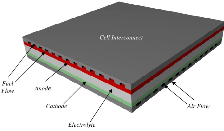
The simplest design of SOFC is the planar design (Figure 1.8). This bipolar or flat late structure enables a simple series electrical connection between cells without the long current path through the tubular cell. Since the design is so simple, gas tight seals
[image:28.595.115.476.219.430.2]are required along the edges of the ceramic plates.
Figure 1.8: Flat-plane design SOFC.
The bipolar flat plane results in lower ohmic losses than in the tubular
arrangement, leading to a superior stack performance and higher power density. The resistance of the cell depends only on the thickness of the component layers; the
production of ultra-thin plates will minimise the resistance, introducing the possibility or lowering cell operating temperature. Another advantage of the planar design is that the electrodes production process can easily be accomplished by mass production
methods such as screen printing and tape casting; cheaper than processes such as chemical vapour deposition (CVD) used in tubular design cells.
Cell Interconnect
Anode
Cathode
Electrolyte Fuel
Flow
Recent developments in SOFC design have seen the appearance of certain hybrid fuel cells, with one such design being the SOFCroll from St Andrews Fuel Cells[27] (Figure 1.9). The design takes form as a double spiral, providing separation of
the gases and a strong tubular form. The clever use of geometry removes mass and components from the fuel cell and simplifies the manufacturing process, thus reducing
[image:29.595.132.546.284.611.2]overall cost[27].
Figure 1.9: St Andrews Fuel Cells SOFCroll design[27].
The fuel and oxidant gases are inserted into the central holes of the tube and are
forced thorugh the porous electrode around the sprial structure, making the supportive Air Flow
Fuel Flow
Anode
Cathode
parts of the cell the active parts. This reduces the amount of material needed in cell production.
1.2.11 Applications
The applications of fuel cells have the potential to be widespread. In principle, fuel cells can be used in a wide variety of areas as a source of electricity – in satellites and space stations, mobile and stationary electrical power sources of all sorts, power
plants, and the drive systems for automobiles. Even sea going vessels have had onboard power provided by fuel cells[28]. Currently, BMW are looking to fuel cells as a power
source for auxiliary devices on automobiles where, otherwise, the power would come from the internal combustion engine. This means the engine could be of a lower capacity, resulting in fewer emissions[29]. Recent attention has been drawn to supplying
power for mobile electronics such as laptop computers, using methanol as a fuel[30].
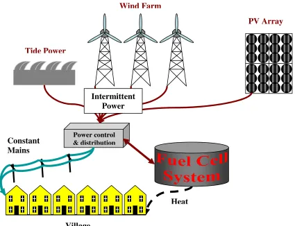
Since fuel cell efficiency is good regardless of size, fuel cells could be sited in decentralised regions, integrated into a system. An example of this, Figure 1.10, sees intermittent renewable energy such as tidal power and photovoltaics supplying power to
a village. On peak power production, excess electricity may be diverted towards a reversible fuel cell, which then produces hydrogen as an energy store. The fuel cell may
Figure 1.10: A reversible fuel cell integrated into a system.
1.2.12 Environmental Issues
When pure hydrogen is used as a fuel in a fuel cell, it can be seen that, in the overall reaction, water is the only by-product. Even if fuelled by means of a
hydrogen-providing compound (such as methanol), where reforming exists, emissions from such a fuel cell are lower then the internal combustion engine equivalent[31]. Since hydrogen is
not a primary fuel – and most hydrogen is derived from hydrocarbons- ways of producing hydrogen from renewable sources must be implemented e.g. photovoltaics, wind turbines. Near-term, hydrogen may be produced from coal or natural gas where
the CO2 is sequestered.
Heat Wind Farm
Village
PV Array
Tide Power
Constant Mains Electricity
Power control & distribution
Another point to consider is the fact that our reserves of fossil fuels are finite in an age of fossil fuel reliance. The price of wholesale gas in the UK has been increasing as the country's stocks in the North Sea have declined, forcing more to be imported
from Europe[32]. Wholesale gas and energy prices have also risen in line with the high cost of oil, which has increased because of political instability in the Middle East and
strong global demand led by fast-growing economies such as China. A more efficient use of existing fossil fuel stocks (such as the use of fuel cells) may assist to prolong life of fossil fuels, and reduce political reliance we have on fossil fuels.
The earth’ s climate is under continuous change. In the past, prior to events such
as the industrial revolution, climate change has been as a result of natural causes. Indication of climate change may be determined from paleoclimatic data gathered from various samples such as ice cores and sediments[33]. Nowadays, however, the term
‘climate change’ is generally used when referring to changes in our climate which we have identified since the early part of the 1900s. The changes we’ ve seen over recent
years, and those which are predicted over the next 80 years, are thought to be mainly as a result of human activities rather than due to natural changes in the atmosphere[34] (though this is still disputed by some). The rapid increase in the greenhouse gases such
as carbon dioxide is generally attributed to the enhanced greenhouse effect (Figure 1.13). The rise in humanity's emissions of carbon dioxide has accelerated sharply,
Figure 1.13: ‘Hockey stick graph’ from a study showing a recent sharp increase in temperatures[35].
1.2.13 Summary
Solid oxide fuel cells offer a cleaner, more efficient way of producing electrical
energy, which may reduce our reliance on fossil fuels. However, there are still problems to overcome such as the materials selection, and especially in the cathode, which seems
to be the limiting step in the electrochemical processes concerned.
1.3 The Chemistry of the Common Electrolytes
1.3.1 Yttria-Stabilised Zirconia
The importance of zirconia in engineering ceramics is well recognised, the long list of functional applications includes high-temperature devices, thermal barriers and
oxygen sensors[36]. Pure Zirconia (ZrO2) has the fluorite structure (Figure 1.12). The
structure consists of a cubic close packed array of zirconium ions, with oxygen
occupying all the tetrahedral sites between the close packed layers. The cubic close packed layers of metal ions are oriented parallel to the [111] planes of the unit cell.
Zirconia can exist as three different polymorphs (Figure 1.13) at ambient pressure (monoclinic, tetragonal and cubic) with an additional orthorhombic phase
reported at high pressure[37]. The differences in structures of the polymorphs are given in the table of cell angles and lattice parameters in Table 1.3.
Figure1.12: The cubic fluorite structure. Zr
Figure 1.13: Structures of the (a) monoclinic, (b) tetragonal and (c) cubic polymorphs of zirconia[36].
Monoclinic Tetragonal Cubic
Space Group P21/c Space Group P42/nmc Space Group Fm3m
a = 5.3129 Å a = 5.094 Å A = 5.090 Å
b = 5.2125 Å c = 5.177 Å
c = 5.1471 Å = 99.218°
Table 1.3: Crystallographic data for the three polymorphs of zirconia[38, 39].
The monoclinic structure of zirconia alters to the tetragonal form above 1000 °C,
and at high temperature zirconia adopts the cubic fluorite structure [40]. The monoclinic polymorph is stable at room temperature and undergoes a reversible phase
transformation to the tetragonal polymorph at 1170 °C[41]. Additional heating to above
polymorph. The cubic polymorph of zirconia distorts at room temperature, which is something not observed in other M2+F2 and M4+O2 compounds with a fluorite structure
e.g. CaF2 is cubic at room temperature; the ionic size ratios of the M and F2/O2 permit
room temperature ideal cubic form.
The volume expansion caused by the cubic to tetragonal to monoclinic transformation induces very large stresses, and will cause pure ZrO2 ceramics to crack
upon cooling from high temperatures. Several different oxides are added to zirconia to
stabilise the tetragonal and/or cubic phases: magnesium oxide (MgO), yttrium oxide, (Y2O3), calcium oxide (CaO), and cerium oxide (Ce2O3), amongst others. Such oxides
form solid solutions with the high temperature cubic polymorph of ZrO2, and these are
stabilised at lower temperatures. MO2 oxides do not exhibit any transition to fast O2- ion
conduction, so it is necessary to introduce anion vacancies into the structure, which
occurs during stabilisation[42]. The stabilisation involves the substitution of the aliovalent cation for zirconium.
1.3.2 Aliovalent Doping
As has been described, zirconia may undergo solid solution formation with several oxides. The introduction of aliovalent dopants can lead to the stabilisation of the
tetragonal and cubic forms of zirconia at room temperature, and also lead to the formation of oxygen vacancies within the structure.
atoms would occur in a perfect crystal structure. One such mechanism for the transport of ions through a solid is where the ion moves from its normal position in the lattice to a neighbouring vacant site (Figure 1.14). Viewed in another way, it may also be described
as the movement of a vacancy – one vacancy is taken up leaving another one free; a vacancy movement. Ions may also move between interstitial sites in a crystal[43].
Figure 1.14: By altering the composition using metal ions of lower charge, oxygen vacancies are introduced, allowing movement of O2- in the metal oxide lattice.
Defects that occur in the solid structure at isolated atomic positions are known as
point defects. Point defects may be created by chemical doping in point defect reactions. In such reactions, where ions of a lower charge are introduced, charge neutrality must
be observed. As noted, the doping of species to create oxygen vacancies gives rise to oxide on conduction (a requirement of the SOFC electrolyte).
The doping of zirconia with yttria can be summarised using Kröger-Vink notation:
X O X
Zr O
Zr 4
2 + Y →2O3 2 + YZr′ VO + 3OOX (Equation 1.7)
The ionic radii of the dopant ions is larger than that of the zirconium cation, the tetragonal and cubic polymorphs are easily stabilised at lower temperatures due to increase in average cation radius. This allows an increase in cation co-ordination from 7
to 8 fold. Table 1.4 shows some of the larger-than-Zr4+ cations used to stabilise zirconia.
Cation Atomic Radii (Å)
Zr4+ 0.98
Mg2+ 1.03
Ca2+ 1.26
Y3+ 1.16
Gd3+ 1.19
Ce4+ 1.11
Table 1.4: Ionic radii of various cations which may be used to dope zirconia (Co-ordination VIII)[44].
The addition of increasing amounts of trivalent dopant such as Y3+ is eventually counter productive since the oxygen vacancies and the dopant ions have opposite
effective charge, so they can attract each other and form immobile defect clusters at high concentrations. 9 mol % Y2O3 is needed to stabilise ZrO2 in its cubic form. Figure
1.15 illustrates the variation in ionic conductivity with dopant concentration, for a
Figure 1.15: Variation in conductivity with dopant concentration for various doped zirconias at 800 °C[45].
1.3.3 Ionic conductivity
Ionic conductors permit the movement of ions through the lattice; solid oxygen ion conductors permit the moment of oxygen ions through the metal oxide lattice.
Mixed conductors permit both oxygen ions and electrons.
Ionic conductivity, , may be defined in the same way as electronic conductivity:
Where:
n = the number of charge carriers per unit volume.
Ze = The charge of the charge carriers (multiple of charge on an electron, e = 1.602189 x 10⁻¹⁹C).
= Charge carrier mobility, a measure of the drift velocity in a constant electric field.
Ionic conductivity, , normally shows an Arrhenius-type behaviour:
= A exp (-Ea/KT) (Equation 1.9)
Where:
Ea = Activation energy (eV). A = Pre-exponential factor.
k= Boltzman constant, 1.38 x 10⁻²³ JK-1. T = Temperature (K).
For a fixed number of oxygen vacancies in any ionic conductor, the ionic conductivity increases with temperature in a typical Arrhenius fashion with an
activation energy of about 1 eV.
Ions jump from site to site, requiring vacant sites in the process. Jumps require
thermal energy to get over an energy barrier, hence heating of YSZ. A low Ea is
Figure 1.16: Representation of the change in energy during the movement of an ion between lattice sites.
1.3.4 Ceria (CeO2)-based and other SOFC Electrolytes
Another electrolyte material that has received much attention as a contender for
use in SOFCs is the cubic fluorite, ceria (CeO2). It has been shown that solid solutions
of ceria show higher oxygen ion conductivity values than yttria-stabilised zirconia
(Figure 1.17). Typically the ionic conductivity of gadolinium-doped ceria (CGO) is more pronounced at lower temperatures e.g. at 700 °C the conductivity of CGO is 5.8 x 10⁻³ Scm-1 as compared to 1.4 x 10⁻⁴ Scm-1 for YSZ[46]. This reduced temperature of
operation will be beneficial in terms of a decrease in the number of thermally related materials problems such as exchange of ions between component layers and/or the
limitation of cracks between component layers. It may also reduce the chance of reactions occurring between the fuel cell components, and especially more so in composite electrodes.
The dopant normally used to dope ceria is gadolinium in the compounds
Ce0.9Gd0.1O2- and Ce0.8Gd0.2O2- . Usually a higher Gd content gives a better impurity
tolerance but lowers lattice conductivity. Position
Energy
Figure 1.17: Comparative conductivities of various electrolytes[46].
n-type electronic conduction is evident in CGO at temperatures approaching 600
ºC and above, a cause which may be attributed to the reduction of a variable valency
ion, Ce4+. The redox behaviour of this ion results in the introduction of electronic conductivity when the oxygen partial pressure is low. This may be denoted using Kröger-Vink notation:
X O
O VO + ½O2 + 2e’ (Ce3+) (Equation 1.10)
The unfavourable increase in electronic conductivity lowers cell efficiency at low power, becoming worse as temperature increases; the maximum operating
Oxides based on Bi2O3 exhibit high oxide ion conductivity e.g. Bi2V0.9Cu0.1O5.35
has an oxide ion conductivity 50 to 100 times greater than any other electrolyte at 300ºC but suffers, like CeO2, from problems on redox[47].
1.4 Oxygen Deficiency in Perovskites
Much work has been carried out on the deficiency of the A and B sites in perovskite structures, yet it seems little attention has been focussed on oxygen
deficiency. Experimental work has been carried out on alkaline earth/transition metal perovskites in various gas atmospheres; in air, inert gases or oxidising atmospheres they
appear stable to temperatures up 1300 K[48]. In hydrogen i.e. reducing conditions, the formation of oxygen-deficient phases is noted. Differing arrangements of oxygen vacancy ordering have been observed (Figure 1.18).
In (a) structures are shown to be composed of corner-sharing BO6 octahedra
with BO5 pyramids in the stoichiometry range between ABO3 and ABO2.5. Several
phases with ordered vacancies have been produced, including oxygen deficient barium
lead oxide perovskites[50]. It has also been shown that the process of oxygen vacancy creation is reversible, rendering the materials of interest as catalysts. (b) displays
structures formed of interlinking layers of corner-sharing BO6 and BO4 planar squares.
(c) also incorporates corner-sharing BO6 octahedra, though linked by linearly
co-ordinated B cations. (d) details structures formed of inter-linked layers of corner-sharing
BO6 octahedra and BO4 tetrahdra[51].
1.4 Conductivity
1.5.1 Electronic Conductivity
The electronic structures of solids may be treated in a uniform way in terms of
molecular orbital theory. Atoms of a solid may be considered as a singular one-dimensional array, with each atom having an s orbital available for the formation of molecular orbitals. An atom contributes an s orbital at a certain energy (Figure 1.19 (a)),
with the possibility of overlap with a second orbital from another atom; the overlap creates a bonding and an antibonding orbital Figure 1.19 (b)). A third orbital from
another atom may then overlap its neighbour, forming three molecular orbitals from the three atomic orbitals (Figure 1.19 (c)). Bringing up successive atoms appears to spread the range of energies covered by the molecular orbitals, and also fills in the range of
larger, the difference between the neighbouring energy levels is infinitely small. The band consists of N different molecular orbitals, the lowest energy orbitals being fully bonding, and the highest energy orbital being fully antibonding (Figure 1.19 (e)).
Although the band appears continuous, it does consist of N different orbitals, even when
N approaches infinity.
The band formed from the overlap of s orbitals is known as the s band. Should the atoms have p orbitals available, the same procedure can occur as happened to the s
orbitals (Figure 1.20). If the atomic p orbitals lie higher in energy than the s orbitals, then the p band lies higher than the s band, and there may be a band gap; a range of
energies for which no orbitals exist (Figure 1.20).
For a solid formed from atoms able to contribute an electron, there will be N
atomic orbitals, N molecular orbitals, and N electrons to accommodate. Since the bands are so close together in energy, electrons can be excited out of them just by the thermal
motion of the atoms. At T = 0, only the lowest ½N molecular orbitals are occupied, and the highest molecular orbital is known a the Fermi level. There are empty orbitals very close to the Fermi level, so it requires a small amount of energy to excite these
Figure 1.19: Band formation of N molecular orbitals by successive addition of N atoms[51].
Figure 1.20: The s and p orbitals of the atoms are so widely spaced a band gap is formed[51].
(a)
(b)
(c)
(d)
(e)
Electrical conductivity in solids decreases with increasing temperature despite more electrons being excited to the empty orbitals. It may be explained by the fact that the temperature increase causes thermal motion of the atoms, so collisions between the
moving atoms and electrons are more likely; they are less efficient at transporting charge.
1.5.2 Semiconductivity
Should each atom provide two electrons, the 2N electrons will fill the N orbitals of the s band (the band is full). The Fermi level now lies at the top of the band at T = 0,
and there is a gap before the next band begins. Upon increasing the temperature, electrons populate the empty orbitals of the upper band (Figure 1.21). They are now mobile, and the solid has become an electronic conductor, or, more precisely, a
semiconductor. Electronic conductivity depends on the number of electrons promoted across the gap, which increases as the temperature is raised. Large band gaps will result
Figure 1.21: (a) When 2N electrons are present, the valance band is full and the material behaves as an insulator (b) elections populate the conduction band upon thermal excitement; the material becomes an
electronic conductor.
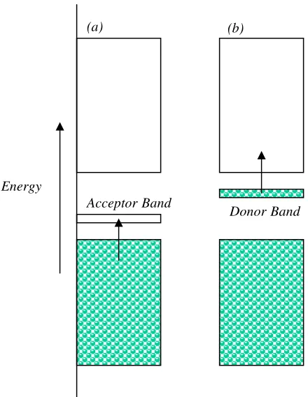
Doping may enhance the semiconductivity of a solid. Such dopants may trap
electrons, withdrawing them from the filled band, leaving holes which allow the remaining electrons to move (p-type semiconductivity)(Figure 1.22 (a)). A dopant may
carry excess electrons, and these electrons occupy otherwise empty bands (n-type semiconductivity)(Figure 1.22 (b)).
Band Gap Thermal Excitation
(a) (b)
alen Conduction Band
Figure 1.22: (a) p-type semiconductor (b) n-type semiconductor.
1.6 The Perovskite Structure, ABX3
The scientist Gustav Rose first described and characterised perovskite and named the mineral – with the formula CaTiO3 - after the Russian mineralogist Count L.
A. Perovski (1792-1856)[52]. Calcium titanate first appeared in the literature about 150
years ago, but until the 1950s lived on a very modest reputation. Perovskites are of the general formula ABX3, where A and B are metallic cations – with A larger than B – and
[image:49.595.181.401.47.331.2]X is an anion (Figure 1.23).
Figure 1.23: Cubic perovskite structure.
(a) (b)
DonorBand AcceptorBand
In looking at the unit cell of a perovskite, it may be described as having cation A in the centre, co-ordinated to 12 oxygen atoms, while the smaller B site is in an octahedral environment (Figure 1.24).
Figure 1.24: Perovskite displaying octahedral environments[53].
The sum of the charges on the A and B ions must be equal to six, but this can be
achieved in numerous ways e.g. A3+B3+ or A2+B4+ (as in the case of BaPbO3). Mixed
oxides are also a possibility e.g. A(B0.5B’0.5)O3 as in La(Ni0.5Ir0.5)O3[54].
A group of perovskite-like compounds is produced when altering only the atoms at the A, B and X sites and possibly their occupancy factors; in some cases there are
resulting changes in the crystal symmetry[52]. Many perovskite compounds are of primitive cubic forms; nearly all having perfect upright BX6 octahedra. The B cations
may be subjected to a displacement – up or down the octahedral diagonals from the cell corners- without necessarily altering the cell symmetry. The structure may become polarised if the displacements are ordered, a result of which may be ferroelectricity.
Lead is a particularly interesting atom from the point of view of the crystal chemistry of perovskites because it can form compounds where it occupies either the large cation (A) or the small cation site (B)[55].
Space groups generally differ in the nature of the tilting of the PbO6 octahedra.
The space group Imma is relatively rare for ABO3 type perovskites, most orthorhombic
perovskite structures, including CaTiO3 itself, are described as being of space group
Pnma[56]. These two structures differ in the tilting of the BO
6 octahedra, Imma having
two equal out of phase tilts (a0 b+ b+) whereas Pnma has both in phase and out of phase tilts (a- b+ b+). Tilting of the octahedra involves a movement of the atoms within the
octahedra, and is more apparent when viewed as an octahedra since a change of axis can be seen. Despite the metallic nature of barium plumbate, that fact that it is of space group Imma is probably related to the relative size of the cations rather than electronic
factors[57].
Metallic oxides with a perovskite structure comprise a large family which exhibits a remarkably wide range of properties, including superconductivity, ferroelectricity, catalysis, and electrochemical effects. In the application of low fatigue
ferroelectric memory, the metallic conductors, such as La0.5Sr0.5CoO3 and SrRuO3 have
been known to serve as an electrode layer[58].
1.7 The Ruddleston-Popper (K2NiF4) structure
Related to the perovskite structure is the Ruddleston-Popper or K2NiF4 structure.
K (A) Ni (B)
[image:52.595.263.380.63.319.2]F (O)
Figure 1.25: K2NiF4 structure[59].
If divided into three sections along the cell’ s c axis, the middle section appears as a B-type perovskite cell unit, and this is sandwiched by two type cell units. The
A-type perovskite cell units have their bottom and top layers missing. In practice the middle section is elongated in the c direction. This elongation is due to the Jahn-Teller
effect.
One of the first publications on the K2NiF4 structure describes several
compounds with the structure: Sr2TiO4, Ca2MnO4 and Sr2La2Al04[60].
Mixed oxides with the Ruddleston-Popper structure have received considerable attention in recent years due to their interesting magnetic and electrical properties e.g. the superconductor La2-xBaxCuO4. The parent compound, La2CuO4, has no
unpaired electrons on the copper ions align antiparallel throughout the structure, locking the electrons to the lattice and stopping conductivity and superconductivity. The introduction of Ba2+, which replaces La, charge compensation is required to preserve
charge neutrality; for every Ba2+ one CuII must be oxidised to CuIII, breaking up the alignment of the unpaired spins. When the averagevalence of the copper atoms reaches
a value of ~2.2, the antiferromagnetism disappears and superconductivity is observed[41].
Work has been done on mixed conducting K2NiF4 structures with a view to
using them as cathodes in SOFCs[61]. Important examples of this family include
rare-earth nickelates, Ln2NiO4+ and cuprates, Ln2CuO4+ . In both Ln–Ni–O and Ln–Cu–O
systems (Ln=La–Gd), the K2NiF4-like A2BO4 phases are most stable in air and are thus
of major interest for high-temperature electrochemical applications[62].
1.8 The Structure and Properties of Compounds in the Ban+1PbnO3n+1 Series
1.8.1 Introduction
An interesting feature of the Ba-Pb-O system is that it may be prepared with an almost cubic perovskite structure (n = , BaPbO3) or a layered perovskite (K2NiF4)
structured phase (n = 1, Ba2PbO4). In addition to this, two other phases have been
determined: Ba3Pb2O7 and Ba4Pb3O10[63], though it has not been possible to prepare
Figure 1.26: Primitive unit cells for phases in the Ban+1PbnO3n+1 series[63].
The two end members of this series (n = 1 and n = ) exhibit semiconductivity and metallic conductivity, respectively.
1.8.2 BaPbO3 (n = )
BaPbO3 has a distorted perovskite structure, deviating from the normal cubic
perovskite (Figure 1.27 (a)); it is an orthorhombic distortion of the perovskite structure
(Figure 1.27 (b)) with the space group Imma. This is only one of the possible structures that can result from a perovskite. The type of distortion seen is related to the radii of the
Figure 1.27: (a) Orthorhombic perovskite (b) Cubic perovskite.
BaPbO3 possesses lattice parameters related to that of the ideal cubic-perovskite
structure by a ≈ 2ap, b ≈ 2ap, c ≈ 2ap where ap is the lattice parameter of the ideal
perovskite. The structure of BaPbO3 consists of the PbO6 octahedra tilted around the
primitive [110]p axis[58]. It is noted that the octahedra tilt differently when replacing the
A site with Sr or Ba.
The structure and properties of stoichiometric and non-stoichiometric BaPbO3
have long been of interest as a consequence of the presence of superconductivity in phases in the perovskite type BaPb1-xBixO3 system[64] e.g. the 3.5K and 12K
superconductors BaPb0.75Sb0.25O3 and BaPb0.75Bi0.25O3[65]. A metal-semiconductor
transition has been noted atx≈0.35 for the Bi system. These discoveries have prompted a series of experimental investigations of the physical and electronic properties of this alloy system. Such studies have included superconductivity,
crystallographic, transport, specific heat, optical absorption, electron-tunnelling, x-ray photoemission and Mössbauer measurements[64]. It has been shown, using a
(a)
combination of the above methods, that the structure of changes as a function of increasing x from orthorhombic tetragonal orthorombic monoclinic.
It is widely recognised that barium plumbate’ s room temperature metallic
conductivity may be attributed to the overlap of the Pb-6s and O-2p orbitals at the Fermi level (Figure 1.28)[66]. Band structure calculations have shown the presence of such a strongly hybridised band at the Fermi level involving the energetic overlap of the
previously mentioned orbitals. This broad band is only partially occupied by the available electrons and therefore metallic conductivity can occur. Thus BaPbO3 is not
really a normal valence compound like its ionic insulating neighbour BaSnO3, where
[image:56.595.267.383.377.616.2]such cation-oxygen hybridisation apparently does not occur.
Figure 1.28: LAPW band gap results for BaPbO3[62].
A few other oxides have been found to be metallic electronic conductors – such as RuO2 and IrO2. Many are semiconductors - also an electronic process - with
As described, the structure of the ideal perovskite oxides, ABO3, consists
essentially of a framework of the parallel BO6 octahedra linked by their sharing corners,
with a large A cation occupying a cavity about the same size as an O anion. If the radius of A becomes smaller, the BO6 octahedra may tilt relative to one another in order to
reduce the size of the cavity occupied by A. In BaPbO3, the octahedra tilt about 8.4º
around the [110]p axis. It has been found that upon replacing Ba with Sr, the tilting
angle of the PbO6 octahedra is much larger (15.1º)[65]. In BaPbO3, the Pb4+ ions remain
Centro symmetric; but the larger cations are allowed to displace. In BaPbO3, Ba2+
cations remain in the ideal positions within the standard deviation. The PbO6 octahedra
in BaPbO3 are only slightly distorted in shape cf. the distortions in SrPbO3[65].
The strength of the Pb-O bond in BaPbO3 has often being remarked upon, with
articles suggesting its instability in reducing atmospheres of hydrogen, even 5%H2/Ar.
In BaPbO3, the Pb-O bond is susceptible to react with hydrogen, combining to form an
O-H bond, therefore debonding Pb-O. This results in the loss of the BaPbO3 cells, and is
a process favoured by the high valence state of lead in BaPbO3 (IV). Under certain
conditions, Pb tends to transform to lower valence states.
The band structure for BaPbO3 may also be applied to that used for SrPbO3, as
its structure is essentially the same array of PbO6 octahedra. As noted before, in SrPbO3,
the increase in Pb-O distances and the larger deviation of the O-Pb-O angles from 90 degrees reduce the effective overlap of the 6s-2p orbitals. SrPbO3 has poorly
Attempts to substitute Pb metal in the compounds BaPb1-xCuxO3 Ba1-xLaxPbO3 have
been made, the dopant ion sizes chosen based on ionic radii considerations. The substitutions in BaPbO3 are attempted to drive the metallic properties of BaPbO3
towards a semiconductor by creating either oxygen vacancies (Cu-substitution) and/or allowing partial reduction of Pb4+ to Pb2+, thereby stabilising the unusual 3+
intermediate valency for Pb in the lattice ( La substitution)[66].
Room temperature resistivity in BaPbO3 has been reported to be around 1
m cm in films of varying thickness[64]. It has been reported that BaPbO3 becomes
insulating at a certain threshold thickness of 1200 Å. A study on the Hall coefficient
shows the mobile carriers in BaPbO3 to be electrons[65]. In a periodic lattice, the
potential function uk (r) will be disturbed near the surfaces due to lattice distortion. This
will have an effect on the motion of the electrons, so when the film thickness is of
certain value, the disturbed potential takes dominance in the motion of electrons and greatly affects the conducting behaviour[64, 65].
The occurrence of a threshold value where insulation ensues has also been described in the electron scattering theory at the surface. This topic has been discussed
and a relationship shown between the film resistivity ( f) and that of the bulk ( 0):
0/ f = (3/4) k [ln(1/k) + 0.423][65] (Equation 1.11)
Where:
0 is the mean free path of the electrons[64].
1.8.3 Ba2PbO4 (n = 1)
Unlike BaPbO3, even though the valance state (4+) and co-ordination geometry
around the Pb are the same (PbO6 octahedra), the K2NiF4 type (tetragonal) Ba2PbO4 is a
semiconductor with a band gap of ~1.7 eV (Figure 1.29).
[image:59.595.239.426.279.504.2]
Figure 1.29: Energy-band results for Ba2PbO4 showing band gap of ~1.7eV[61].
Band structure calculations have shown that a shortened axial Pb-O distance which induces sp interactions between Pb-6s and O-2p orbitals is instrumental in
opening the band gap.[66] Ba2Pb1-xBixO4-yFy compositions have been produced, aiming to
modify the co-ordination geometry around Pb in an attempt and to induce metallic
1.9 Summary and Aims
There are still problems to overcome in realising solid oxide fuel cells. One such
problem is the materials selection, and especially in the cathode, which it seems is the limiting step in the electrochemical process. New materials selection along with
functionally graded composite cathodes may address this issue. Two phases in the Ba-Pb-O system (BaPbO3 and Ba2PbO4) have been previously produced as phase pure
samples. The differing properties of these phases may be usefully applied to a new
cathode.
The aim of this work is to synthesise the phases BaPbO3 and Ba2PbO4 and
investigate their suitability as solid oxide fuel cell materials. These materials will be tested for stability under fuel cell operating conditions and for compatibility with
common SOFC electrolytes. A.C. impedance spectroscopy will be performed on the samples to determine electrochemical performance. The doping of plumbates with both
Sc and Y will be performed and tests to determine any changes in electrochemical performance will be carried out. The plumbates will also be tested as a candidate for use in a composite electrode.
1.10 References
[1]- S. Nelson, Chemistry in Britain, 1989, 1184.
[2]- D. Lide, Handbook of chemistry and Physics 76th edition, CRC Press,
1995-1996.

![Figure 1.9: St Andrews Fuel Cells SOFCroll design[27].](https://thumb-us.123doks.com/thumbv2/123dok_us/8567055.367373/29.595.132.546.284.611/figure-st-andrews-fuel-cells-sofcroll-design.webp)
![Figure 1.13: ‘Hockey stick graph’ from a study showing a recent sharp increase in temperatures[35]](https://thumb-us.123doks.com/thumbv2/123dok_us/8567055.367373/33.595.125.532.68.271/figure-hockey-stick-graph-showing-recent-increase-temperatures.webp)
![Figure 1.25: K2NiF4 structure[59].](https://thumb-us.123doks.com/thumbv2/123dok_us/8567055.367373/52.595.263.380.63.319/figure-k-nif-structure.webp)
![Figure 1.26: Primitive unit cells for phases in the Ban+1PbnO3n+1 series[63].](https://thumb-us.123doks.com/thumbv2/123dok_us/8567055.367373/54.595.165.478.73.301/figure-primitive-unit-cells-phases-ban-pbno-series.webp)

