ECG Signal Analysis using Wavelet Filtering
Vikas Dubey1, Nayanica Srivastava2 1, 2
Electronics Engg. Deptt. Harcourt Butler Technical University Kanpur U.P-India
Abstract: In the current era, the use of engineering in the field of bio-medical has increased. In bio-medical engineering, automated systems are developed to obtain patient important parameters even in the absence of medical experts. In the similar context ECG is one of the important parameters which is measured to monitor the health of human heart. This paper deals with basic processing of ECG including 60 Hz glitch and baseline wander removal.
Keywords: ECG, notch filter, Baseline Wander, wavelet, DWT
I. INTRODUCTION
Evidence of biomedical engineering can be found everywhere in modern medicine. Bio-medical engineering offers various advantages over like reduction in hospitalization cost, automated and quick reports, and patient care even in the absence specialized doctors. The transform of the signal is just another form of representing the signal. In Fourier theory a signal can be represented as the sum of a possibly infinite series of sinusoids, which is referred to as a Fourier expansion. Fourier expansion works well with time invariant signals. For a time-varying signal, a complete characterization in the frequency domain should include the time aspect, resulting in the time-frequency analysis of a signal. In the past many solutions have been developed which are more or less able to represent a signal in the joint time-frequency domain, which include the short time Fourier transform (STFT) and wavelet transform [1-3].
The wavelet transform provides the time-frequency representation of the signal. There has been intensive research on wavelets. In particular, Mallat and Meyer discovered a close relationship between wavelet and multi-resolution analysis, which leads to a simple way of calculating wavelet functions. Their work also established a connection between wavelet and digital filter-bank. Daubechies developed a systematic technique for generating finite-duration orthogonal wavelets with finite impulse response (FIR) filter banks [4-6].
The major outcomes of recent studies on wavelet transform indicate that development of several new applications. One of a promising application of wavelet transforms is in the field of digital wireless communications where they can be used to generate waveforms that are suitable for transmission over wireless fading channels.
II. NOTCH FILTERING.
Signal x(n), which in this case is a pure ECG signal. However, the signal that we obtain, y(n) , is not a pure ECG signal; it is an ECG signal corrupted with a noise signal, w(n). . In other words, y(n)= x(n)+ w(n), and we are interested in filtering out w(n).
For the purposes of this problem, we consider
w n
( )
A
cos(
n
)
for several reasons: this noise signal simulates the actual problem well, and is a real-valued signal. Now, we know that the cosine function contains two frequencies ±Ω and in order toremove the error signal from y(n), we need to notch out these frequencies. Thus, a notch filter will satisfy the requirements of this problem. Let us flesh out this notch filter, which we will call N.
In order to notch out two frequencies, we should consider each frequency separately and notch it out separately. With this in mind,
generate the necessary frequency response, N(ω), for the filter N. It should have the form
1 2 1 2
(
)(
)
( )
(
)(
)
j j j je
z
e
z
N
e
p
e
p
. (1)Notch filters can be used to remove certain frequency components which are un-desirable by placing zeros at those locations. The radius of the zeros should be equal to unity, while angle of zeros should be at
0
0
(2 )
s
f
f
. 0 1 jz
e
and 02
j
0 0
2
sf
f
1 2 2(
)(
)
[ ]
z
z
z
z
H z
z
. (2)In our case fs=200 Hz, and f0=60 Hz, therefore
2 2
0.618
1
[ ]
Nz
z
H
z
z
(3)III. BASELINE WANDERS
Baseline drift may occur due to voltage fluctuations in the recording device. But one of the main reasons for baseline drift is the movement of the subject while the recording is going on due to over-excitement, discomfort, even tension, anxiety etc. can cause suitable amount of baseline drift which incurs significant errors in the subsequent extraction of data or we can say the baseline wander is unwanted drift in ECG signals around the baseline, and this can arise due to breathing, body movements, electrode behavior etc. The baseline wanderer generated fluctuation in ECG can lead to incorrect identification of STEMI and non-STEMI patients [7].
IV. REMOVAL OF BASELINE WANDER ERROR USING DWT
Wavelets are small waveforms with a set oscillatory structure that is non-zero for a limited period of time (or space) with additional mathematical properties. The wavelet filters are characterized with wavelet bases. These signal transmission techniques allow for significant increase in wireless capacity without increase in bandwidth.
The baseline wander can be modeled as summation of sinusoids whose amplitude and phase varies randomly.
0
.
Cos(2
)
k
w k k
j
b
C
a
k ft
(4)with,
f
f
sN
, where fs is the sampling frequency and N denotes the total number of samples in ECG. In the above equation ak isa random variable uniformly distributed between [0;1] and Φk is random phase uniformly distributed between [0;2π].
This baseline wander is added to the ECG signal:
( )
( )
w( )
y t
x t
b t
(5)Where, x(t) is actual ECG signal free from baseline wanderer y(t) is recoded ECG signal. The discrete wavelet transforms [8]
0 0 , 0 0
1
( )
mm n m m
t
nb a
t
a
a
(6)The parameters m and n used to measure dilation and translation respectively. The most preferred choice for a0 and b0are 2 and 1 respectively [9].
/ 2
,
( )
2
2
m m
m n
t
t
n
(7)Under the condition that
, ,
1 if
,
( )
( )
0 otherwise
m n p q
m
p n
q
t
t dt
(8)The wavelet co-efficient are obtained as
,
( )
,( )
m n m n
T
y t
t dt
(9)
,
( )
2
2
m n
t
t
n
(10)With the property that
0,0( )
t dt
1
,
( )
,( )
m n m n
S
y t
t dt
(11), ,
( )
( )
m m n m n
n
y
t
S
t
(12)0
0, 0, , ,
( )
( )
( )
m
m n m n m n m n
n m n
y t
S
t
T
t
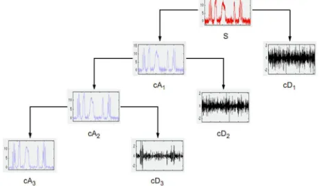
(13) [image:3.612.194.428.311.447.2]In the above signal first term denotes the slowly varying changes in signal, while the second term denotes the rapidly varying signal. By carefully selecting the wavelet the baseline wander can be modeled as slowly varying signal and finally subtracting the estimated baseline wander from y(t) to obtain x(t) which is actual ECG signal free from baseline wander. The signal decomposition using wavelet transform is shown in Fig. 1.
Figure 1: Signal decomposition using Wavelet transform
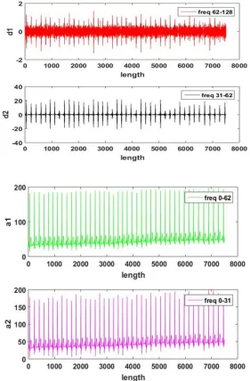
The signal decomposition using, Nyquist sampling criterion is shown in figure 2.
Figure 2: Signal decomposition using, Nyquist sampling criterion
Using equation 13, each decomposed signals is represents as exact and approximate signals and approximate signal is subtracted form original signal to obtain the exact signal.
Mathematically,
y[n]=x[n]+w (14)
[image:3.612.183.423.495.586.2]Figure 3: Signal with random wanderer
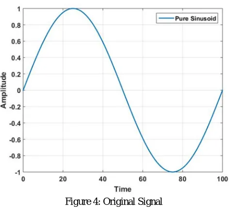
Figure 4: Original Signal
V. SIMULATION WORK
All the simulation work is done through the MATLAB. In figure 5, a raw ECG data is shown which is taken from MIT-BIH Arrhythmia database which is corrupted from baseline wander error.
[image:4.612.146.491.579.716.2]
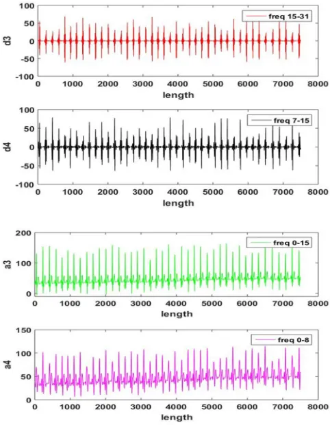
Figure 7: Wavelet based signal decomposition
VI. RESULTS
In figure 6, comparison of original and filtered ECGs is shown. The filtered signal is free from baseline wanderer. The shifting in curves is observed due to filtering mechanism.
Wavelet decomposition of original ECG signal at various frequency in form of approximation and detail coefficient is shown on figure7.
VII. CONCLUSION
This paper discusses the fundamental issues related to ECG signal processing. The removal of 60 Hz frequency along with concept of baseline wanderer error, which is eliminated by wavelet filtering.
REFRENCES
[1] Narwaria, R.P., Verma, S. and Singhal, P.K., 2011. Removal of baseline wander and power line interference from ecg signal-A survey approach. International
Journal of Electronics Engineering, 3(1), pp.107-11.
[2] Islam, M.K., Tangim, G., Ahammad, T. and Khondokar, M.R.H., 2012. Study and analysis of ecg signal using matlab&labview as effective tools. International
journal of Computer and Electrical engineering, 4(3), p.404.
[3] Gokhale, P.S., 2012. ECG Signal De-noising using Discrete Wavelet Transform for removal of 50Hz PLI noise. International Journal of Emerging Technology
and Advanced Engineering, 2(5), pp.81-85.
[4] Singh, O. and Sunkaria, R.K., 2017. ECG signal denoising via empirical wavelet transform. Australasian physical & engineering sciences in medicine, 40(1),
pp.219-229.
[5] Luo, Y., Hargraves, R.H., Belle, A., Bai, O., Qi, X., Ward, K.R., Pfaffenberger, M.P. and Najarian, K., 2013. A hierarchical method for removal of baseline
drift from biomedical signals: application in ECG analysis. The Scientific World Journal, 2013.
[6] Zhang, D., 2006, January. Wavelet approach for ECG baseline wander correction and noise reduction. In 2005 IEEE Engineering in Medicine and Biology 27th
Annual Conference (pp. 1212-1215).
[7] Xu, L., Zhang, D., Wang, K., Li, N. and Wang, X., 2007. Baseline wander correction in pulse waveforms using wavelet-based cascaded adaptive filter.
Computers in Biology and Medicine, 37(5), pp.716-731.
[8] Kaur, M. and Singh, B., 2011, February. Comparison of different approaches for removal of baseline wander from ECG signal. In Proceedings of the
International Conference & Workshop on Emerging Trends in Technology (pp. 1290-1294). ACM