© 2019, IRJET | Impact Factor value: 7.211 | ISO 9001:2008 Certified Journal | Page 4490
Behaviour of Cold Formed Steel Built-up Columns by Using Fasteners
C. Veeraiyan
1, S. Karthikeyan
21
PG Student, Department of Civil Engineering, Kongu Engineering College, Erode, Tamil Nadu, India
2
Assistant Professor, Department of Civil Engineering, Kongu Engineering College, Erode, Tamil Nadu, India
---***---
Abstract - The behaviour of any structural members is mainly based on its cross-sectional properties. The effect of connections is mostly not considered in steel design except for the tension members. In this study, the behaviour of cold formed column sections under compression with respect to fasteners were studied. A total of 6 cold formed built up I-section columns with two different types of connections (bolted and welded) were tested under uniaxial compression. In the failure mode, ultimate strength of the specimen was investigated. The test results showed that the columns with welded connection resist more load than the bolted connection. Results are also compared with the manual calculation. From results, it was observed that there is significance difference between manual calculations and axial load capacity of tested columns. Under the application of axial load in bolted and welded connections, initially local buckling failure occurred. The load carrying capacity of welded connection column is higher than the bolted column. Comparison study shows that we can adopt this section as columns instead of using hot rolled sections under light loads and when hot rolled sections proves to be expensive. This will reduce the cost of the material and construction.Keywords: Cold formed steel, Bolted connection, Welded connection, Axial load. 1. INTRODUCTION
In India construction using structural steel is still in developing stages. Currently, we are mostly restricting the use steel structures in industrial buildings alone. But structural steel can be used for a variety of buildings varying from to industrial plants to residential buildings. In addition to hot rolled steel sections, cold- formed steel structures also become increasingly popular in recently years due to their superior strength to weight ratio and ease of construction. In case of lighter loads where hot rolled sections proves to be uneconomical, cold formed built-up sections proves to be a better option both in terms of strength as well as cost. In this regard a study was made on the axial behaviour of cold formed built-up column sections by using welded and bolted built up sections. Axial behaviour of cold formed columns are compared between bolted and welded sections.
2. MATERIAL PROPERTIES
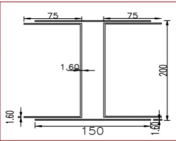
A built up I section with using cold formed steel sheet of thickness 1.6 mm is used in the study. Two channel sections are connected back to back to form an I section and in addition to that, flange plates are used at top and bottom. The flange width and thickness of each channel is 75mm x 1.6 mm. The web depth and thickness of each channel 200mm x 1.6mm. The width of flange plate is 150mm and thickness is 1.6mm. Height of column is used in this study is 650mm. Two channels are connected at top and bottom flanges using those flange plates. One set of connection is made using bolts and another set is made by using weld.
3. SLENDERNESS RATIO
[image:1.595.350.524.467.606.2]The maximum effective slenderness ratio for member carrying compressive load resulting from dead load and imposed loads (KL/r) value should not exceed 180 ‘kL’ is the effective length of member and ‘r’ is appropriate radius of gyration based on effective section. The slenderness ratio for the designed cross section calculated as 20 as it is a short column section.
Fig 1: Cross section with dimensions (mm)
4. CONNECTIONS
Two different types of connections are adopted in this study namely
a) Bolded connection
b) Welded connection
A. Bolted Connection
© 2019, IRJET | Impact Factor value: 7.211 | ISO 9001:2008 Certified Journal | Page 4491 channels. The thickness of flange plate is 1.6mm. In
bolted connection thirty-six bolts are used to connect the channels for the formation of I section. The edge distance and pitch distance spacing of bolts are taken from IS 800:2007. Eight bolts are place at 50mm apart from the edge of each side of column in both top and bottom flange. Then sixteen bolts are connected at top and bottom flange for 110 mm spacing. Twelve bolts are connected web at distance 37.5mm at top and bottom. 10mm diameter bolt are used for connection. For 10mm diameter bolts, 12 mm holes are made in specimen. The top view of I section with bolted connection
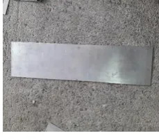
[image:2.595.369.501.211.473.2]Fig2: Flange plate
Fig 3: Flange plate with bolt holes
The following figures shows the bolt connection at flanges and web.
Fig 4: Bolted connection
B. Welded Connection
Spot weld is used to connect the two channel sections to form a I section. Welding is possible in cold form steel with reference taken from the experiments
conducted by Shivakumar Kesawan. Connections are made at the junction of two channels and at end of flanges and at top and bottom of web. Spacing are provided similar to the bolt spacing for comparison. Electrical welding that uses a welding power supply to create an electric arc between an electrode and the cold formed steel sheet to melt the metals at welding point. They can be use either direct current or alternating current and consumable or non-consumable electrodes. Welded connection at flange and web are shown
Fig 5: Welded Connection at flange
Fig 6: Welded connection at web
[image:2.595.100.216.241.520.2]Connections are made at junction by making hole at the connection plate at the center where the junction of two channels are located. The following shown the connection plate
Fig 7: Connection plate
5. EXPERIMENTAL INVESTGATION
[image:2.595.379.494.535.636.2]© 2019, IRJET | Impact Factor value: 7.211 | ISO 9001:2008 Certified Journal | Page 4492
Fig 8: Universal Testing Machine
A. Test set up
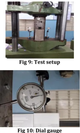
[image:3.595.93.224.350.567.2]Universal Testing Machine (UTM) is used to test the axial compression strength of the specimens. The columns are placed at center of UTM. Plates are placed at top and bottom of the column to distribute the load uniformly throughout the specimen. Specimens are placed at fixed end condition. Loads are applied to the specimen by hydraulic loading. Load carrying capacity is digitally displayed in universal testing machine.
Fig 9: Test setup
Fig 10: Dial gauge
Dial gauge are used to measure the vertical and lateral deflections. Totally three dial gauges are used to measure deflections in specimen. One is placed vertically to measure vertical deflection and remaining two are placed laterally at the center of specimen to measure lateral deflection. The least count of dial gauge is 0.01.Loads are applied slowly to the specimen. For each increment of 5 kN, deflections are measured through dial gauge. There is only minimum amount of deflection in lateral direction due to short column effect. Maximum load carrying capacity of column is reached when local buckling initiates.
Fig 11: Failure mode of Bolted column and Welded column
Further load is applied after the load carrying capacity of column. Load carrying capacity decreases with increase of deflection, crushing failure occur at the top for welded column and for bolted column failures occur at the bottom of column. The following figures represent the crushing failure of welded and bolted columns. The following figures represent the crushing failure of welded and bolted columns
Fig 12: Failure of welded column
Fig 13: Failure of bolted column
6. NUMERICAL CALCULATION
The manual calculation was calculated as per IS 801:1975. Manual calculations are calculated without considering the connections. The ultimate load of the column obtained from this calculation is 80.26 kN.
7. RESULTS & DISCUSSIONS A. Column Test Results
[image:3.595.376.499.446.577.2]© 2019, IRJET | Impact Factor value: 7.211 | ISO 9001:2008 Certified Journal | Page 4493 TABLE 1
Results Type of
section Average (kN) % Increase
Manual
calculation 80.26 -
Bolted
connection 102.75 28.02
Welded
connection 112.36 40.13
The load deflection curve for the experimental results are plotted
Fig 14: Load vs Displacement curve for bolted connection
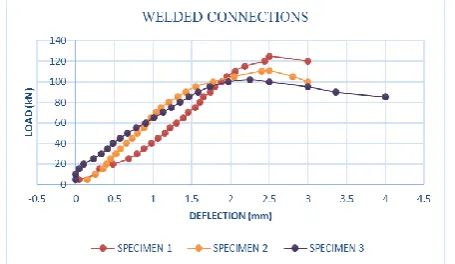
From these results we can easily identify the significant variation in axial load based on the various fasteners. So, when compared to manual design, experimental results give more axial load carrying capacity. Welded connection gives more strength than bolted column and manual calculation. Under experimental investigation, it was found that built up sections with welded connections gives 40% more results than theoretical calculation. Whereas bolted connection gives 28% more strength than theoretical calculations.
Fig 15: Load vs Displacement curve for welded connection
Also, from the comparative study based on different connections, for the light loads this cold formed built up columns proves to be an effective and ecoomic replacement for the conventional hot rolled I sections.
8. CONCLUSION
An attempt has been made to study the behaviour of cold formed built upcolumn’s sections in axial compression under the influence of fasteners. Six columns each of three bolted and three welded cold formed sections were used in the study, it was found that both the columns give more results when compared with the theoretical values. In both the type of fasteners, welded columns provide more strength than the bolted columns.
9. REFERENCES
[1] Aizhu Zhu, Xiaowu Zhang, HongpingZhua, Jihua Zhu and Yong Luc, (2017) ‘Experimental study of concrete filled cold-formed steel tubular stub columns’, Journal of Constructional Steel Research, vol.134, pp.17–27.
[2] David, C., Fratamico, ShahabeddinTorabian, Xi Zhaoc, Kim J.R, Rasmussen Benjamin, W., Schafer, (2018) ‘Experiments on the global buckling and collapse of built-up cold-formed steel columns’ Journal of Constructional Steel Research, vol.144, pp.65–80
[3] Dongyu Liu, Hongbo Liu, Zhihua Chen and Xiangwei Liao, (2017) ‘Structural behavior of extreme thick-walled cold-formed square steel columns’, Journal of Constructional Steel Research, vol.128, pp.371–379.
[4] Essam, A., Amoush, and Mohamed A., Ghanem, (2018) ‘Axially loaded capacity of alternatively strengthened cold-formed channel columns with CFRP’, Journal of Constructional Steel Research, vol.140, pp.139–152.
[5] Helder, D., Craveiro, Joao Paulo, Rodrigues and Luis Laim, (2016) ‘Buckling resisitance of axially loaded cold form steel columns’, Thin-Walled Structures, vol.106, pp.358–375.
[6] Jia-Hui Zhang and Ben Young, (2018) ‘Experimental investigation of cold-formed steel built-up closed section columns with web stiffeners’, Journal of Constructional Steel Research, vol.147, pp.380–392.
[7] Jun Ye, Seyed Mohammad Mojtabaei and Iman Hajirasouliha, (2018) ‘Local-flexural interactive buckling of standard and optimized cold-formed steel columns’, Journal of Constructional Steel Research, vol.144, pp.106–118.
[8] Krishanu Roy, Tina Chui Huon Ting, Hieng Ho Lau and James, B.,P.,Lima, (2018) ‘Nonlinear behaviour of back-to-back gapped built-up
cold-formed steel channel sections under
compression’, Journal of Constructional Steel Research, vol.147, pp.257–276.
[image:4.595.45.273.535.667.2]© 2019, IRJET | Impact Factor value: 7.211 | ISO 9001:2008 Certified Journal | Page 4494 Journal of Constructional Steel Research, vol.110,
pp.16–28.
[10] Sivakumar Kesawan and MahenMahendran, (2017) ‘Section compression capacity of high strength cold-formed hollow flange channels’, Journal of Constructional Steel Research, vol.133, pp.202–213.
[11] Sivakumar Kesawan, Mahen Mahendran, Yomal Dias and Wen-Bin Zhao, (2017) ‘Compression tests of built-up cold-formed steel hollow flange sections’, Thin-Walled Structures, vol.116, pp.180–193.
[12] Vijayanand, S., and Anbarasu, M., (2017) ‘Effect of Spacers on Ultimate Strength and Behavior of Cold-Formed Steel Built-up Columns’, Procedia Engineering, vol.173, pp.1423–1430.