Copyright@1981
DSD 880
DATA STORAGE SYSTEM
USER'S MANUAL
Data Systems Design, Inc. 2241 Lundy Avenue San Jose, CA 95131 (408)946-5800
11VX 910-338-0249
All rights reserved. No part of this manual may be reproduced in any form or by any means without prior written permission of Data Systems Design.
WARRANTY STATEMENT
Data Systems Design's products are warranted against defects in materials and workmanship. For DSD products sold in the U.S.A., this warranty applies for ninety (90) days from date of shipment. *DSD will, at its option, repair or replace either equipment or components which prove to be defective during the warranty period. This warranty includes labor~ parts, and surface travel costs of system modules or components. Freight charges for other than surface travel or for complete systems returned for repair are not included in this warranty. Equipment returned to DSD for repair must be shipped freight prepaid and accompanied by a Material Return Authorization number issued by DSD Customer Service. Repairs necessitated by shipping damage, misuse of the equipment, or by hardware, software, or interfacing not provided by DSD are not covered by this
warranty.
NO OTHER WARRANTY IS EXPRESSED OR IMPLIED, INCLUDING, BUT NOT LIMITED TO, THE IMPLIED WARRANTIES OF MERCHANTABILITY AND FITNESS FOR A PARTICULAR PURPOSE, DSD SHALL NOT BE LIABLE FOR CONSEQUENTIAL DAMAGES.
*For products sold outside the U.S.A., contact your local DSD distributor for warranty terms.
NOTE: ALL ORDERS SHOULD BE PLACED THROUGH THE NEAREST REGIONAL SALES OFFICE.
EASTERN REGION SALES 51 Morgan Drive
Norwood, MA 02062 TEL: (617) 769-7620
~: 710-336-0120
WESTERN REGION SALES 2560 Mission College Blvd. Suite 108
PREFACE
This manual describes the features, specifications, and register usage of the DSD 880' Data Storage System.
Instructions for DSD 880' installation, operation, and elementary troubleshooting are included in this manual.
The material in this manual is subject to change without notice. The manufacturer assumes no ·responsibility for any errors which may appear in this manual.
SAFETY
Operating and maintenance personnel must at all times observe sound safety practices. Do not replace components, or attempt repairs to this equipment with the power turned on. Under certain conditions, dangerous potentials may exist when the power switch is in the off position, due to charges retained by capacitors. To avoid injury, always remove power before attempting repair procedures.
Data System Design, Inc. will accept no responsibility or liability for injury or damage sustained as a result of operation or maintenance of this equipment with the covers removed and power applied. .
WARNING
This equipment generates, uses and can radiate radio frequency energy and, if not installed and used in accordance with the instructions manual, may cause interference to radio communications. As temporarily permitted by regulations, it has not been tested for compliance with the limits for Class A computing devices pursuant to the sub-part J or Part 15 of the FCC rules which are designed to provide reasonable protection against such interference. The operation of this equipment in a residential area is likely to cause interference in which case the user, at his own expense, will be required to take whatever measures may be required to correct the interference.
CAUTION
Do not operate the DSD 880 without first releasing the winchester drive spindle lock mechanism by removing the spindle lock screw and clamp which is accessible from the bottom of the chassis without removal of the cover. Do not rotate the spindle by hand. Moving the spindle in the wrong direction can cause media damage.
TABLE OF CONTENTS
1.0 INTRODUCTION
1.1. General Information 1.2. System Overview 1.3. Features
1.3.1 System Architecture
1.3.2 Off-Line Backup Capability
1. 3.3 Hyper Diagnostics'" 1.3.4 Reliability
1.4. Summary 2.0 SPECIFICATION
2.1. General Information
2.2. DSD 880 Major Components 2.3. Recording Characteristics
2.4. Cable and Connector Require ments 2.5. Power Specifications
2.6. Physical Specifications 2.7. Environmental Requirements
2.7.1. Environmental Specifications 2. 7 .2. Cleanliness
3.0 INSTALLATION
3.1. General Information 3.2. Unpacking and Inspection 3.3. Power Requirements
3.4. Installing the DSD 880 Chassis
3.5. Interface Module and Cable Installation 3.5.1. Preparation
3.6. AC Power Cord Installation
3.7. Initial Checkout and Acceptance Testing 3.8. DSD 880 Initial Program Installation
3.8.1. DSD Supplied Programs 3.8.2. Command Files
3.8.3. Use of DSDMON
3.8.4. Transfer of RT-11 to DSD 880
3.8.5. Transfer of RT-11 V 4 to the 880 Winchester 3.8.6. Double Sided Support Under RT-11 (Version 3B) 3.8.7. The DSD Monitor Patch Program for RT-11 V3B 3.8.8. Double Sided Floppy Support Under RT-11 V 4 3.8.9. Extended Mode Winchester Support
3.8.10. RSX-11M Double Sided Floppy Support 3.8.11. RSX-11M DSD 880 Extended Support
3.8.12. Transfer of RSX-11M to DSD 880 Winchester
TABLE OF CONTENTS (Cont)
4.0 OPERATION
4.1. General Information 4.2. Power On Self Tests 4.3. Mode and Class Selections 4.4. Normal Operation
4.4.1. System Bootstrapping 4.5. Bootstrap Failure Procedure
4.5.1. Troubleshooting Bootstrap Failures 4.6. Off-Line Operation
4.6.1. Format Mode
4.6.2. Backup and Reload Modes
4.6.3. Backing Up the Winchester Disk onto Floppy Disks 4.6.4. Reloading the Wincester Disk from Floppy Disks 4.6.5. HyperDiagnostic Mode
5.0 BASIC PROGRAMMING INFORMATION 5.1. General Information
5.2. Operating Mode
5.2.1. Single-Sided Operation 5.2.2. Double-Sided Operation 5.2.3. Programming Interface
5.3. DSD 880 Floppy Disk Operation and Programming
5.3.1. Addressable Registers in RX02 Compatible Operation 5.3.2. Command and Status Register
5.3.3. Data Buffer Register (RX2DB)
5.3.4. Floppy Disk Controller Command Protocols 5.3.5. Diskette Formatting
5.3.6. Power Fail
5.3.7. Common Programming Mistakes 5.3.8. Interrupts
5.4. DSD 880 Winchester Disk Operation and Programming 5.4.1. Bad-Track Mapping
5.4.2. Normal Mode (RL01 Emulation) 5.4.3. Extended Mode
5.4.4. DEC Bad Block Map 5.4.5. Addressable Registers 5.4.6. Control Status Register 5.4.7. Bus Address Register 5.4.8. Disk Address Register 5.4.9. Multipurpose Register
5.4.10. Winchester Controller Commands 6.0 BASIC CIRCUIT DESCRIPTION
6.1. General Information 6.2. DSD 8832 Interface Board
TABLE OF CONTENTS (Cont)
6.3. DSD 8830 Interface Board
6.4. DSD 880 Controller/Formatter Board 6.5. DSD 8833 HyperDiagnostic Panel 7.0 USER LEVEL MAINTENANCE
7.1. General Information 7.2. Preventative Maintenance
7.2.1. Disk Drive Maintenance 7 .3. Troubleshooting and F aul t Isolation 7 .4. Diagnostic Aids
7.5. Fault Isolation
7.5.1. Use of DSD 880 HyperDiagnostics 7.5.2. HyperDiagnostic Operation .
7.5.3. Error Reporting During HyperDiagnostics 7.5.4. Winchester Write Enable
7.5.5. Floppy Disk Format Routines (Mode 1) 7.5.6. System Tests (Mode 2) .
7.5.7. Controller Tests (Mode 3)
7.5.8. Floppy Disk Allgnment Routines (Mode 4) 7.5.9. Read/Write Tests (Mode 5)
7.6. DSD Error Code Interpretation 7.7. Sub-System Replacement 7.8. Maintenance Assistance
Appendix A - Diskette Directories Appendix B - Command Files Listings
APPENDICES
Appendix C - Floppy Disk Exercisor (FLPEXR) User's Manual Appendix D - Fixed Disk Exercisor (FIXEXR) User's Manual Appendix E - SA1000 Test (SATEST) User's Manual
6-3 6-5 6-7 7-1 7-1 7-1 7-1 7-2 7-3 7-3 7-3 7-4 7-4 7-6 7-6 7-6 7-7 7-8 7-9 7-10 7-21 7-21
A-l
B-1
C-l
Table No. 2-1 2-2 3-1 3-2 3-3 3-4 3-5 4-1 4-2 4-3 4-4 4-5 4-6 5-1 5-2
7-1
7-2 7-3 C-1 C-2 D-1 D-2 E-1 E-2TABLE OF CONTENTS (Cont)
TABLES Description DSD 880 Major Components
. DSD 880 Product Specifications Rack Installation Hardware
DSD 8832 Standard and Alternate Address Configuration DSD 8830 Standard and Alternate Address Selection 8830 Interrupt Priority Settings
8830 Jumper Configurations DSD 880 Indicators
DSD 880 Mode and Class Options
DSD 880 Interface Bootstrap Program Starting Address and Device Address
Program Halt Locations Program Loops
DSD 880 Bootstrap Program Listing Error Register Codes for RX2ES Diskette Format Codes
Floppy Disk Drive Preventative Maintenance Preliminary Troubleshooting Guide
Figure No. 1-1 3-1
3-2
3-3 4-1 4-2
4~3
5-1 5-2 5-3
5-4
5-5 5-6 5-7
5-8
5-9 5-10 6-1 6-2 6-3
TABLE OF CONTENTS (Cont)
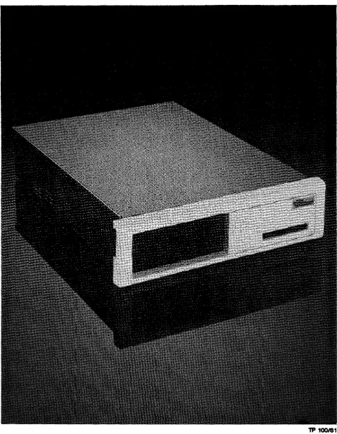
FIGURES Description The Data Systems Design 880
Installing Chassis Slides
DSD 8832 Computer Interface Card DSD 8830 Computer Interface Card DSD 880 HyperDiagnostic Panel
Proper Orientation of Diskette for Insertion Bootstrap Flow Diagram
Command and Status Register
System Error and Status Register Bit Format Control Status (CS) Register Format
Bus Address Register Format
Disk Address Register Format During A Seek Com mand Disk Address Register Format for a Read or Write Command Disk Address Register Format for a Get Status Command Multipurpose Register Format for a Get Status Command Multipurpose Register Format for a Read Header Command Multipurpose Register Format for a Read/Write Data Command DSD 880 Block Diagram
DSD 8830 Interface Board Block Diagram DSD 8840 Controller/Formatter Board
Page 1-1 3-3
3-4
3-5 4-2 4-10 4-12
5-3
5-6 5-17 5-20 5-20 5-21 5-21
5-22 5-23 5-24
TP 100181
[image:11.620.67.550.66.687.2]1.0 INTRODUCTION
1.1 General Information
This manual provides user information for the DSD 880 data storage system. Coverage provided includes: features, specifications, installation, operation, elementary programming and user level troubleshooting.
1.2 System Overview
The DSD 880 is a compact data storage system combining the advantages of the winchester disk system .and the floppy disk system. Designed for use with computers manufactured by Digital Equipment Corporation (DEC), the DSD 880 provides the large capacity, rapid data access, and reliability of winchester disk technology and the low cost versatility of the floppy disk in a compact, system oriented package.
The DSD 880 is shown in Figure 1-1.
1.3 Features
1.3.1 System Architecture
The DSD 880 uses a unique system architecture to achieve the economy and performance available by the combination of winchester and floppy disk technologies. The winchester is configured to be compatible with a high performance disk system (the DEC RL01/RL02) while the double sided floppy disk emulates a floppy disk system (the DEC RX02). The DSD 880 is fully hardware, software and interface compatible with DEC computers. The system provides 8.8 MB of on-line storage (7.8 MB fixed and 3 MB
removable). .
The DSD 880 is implemented with a controller/formatter that is common in both drives. A single computer interface simplifies system integration. A bit-slice processor on this interface arbitrates device requests and queues pending instructions. Each disk drive responds to a different device address, interrupt priority and interrupt vector.
The DSD 880 controller uses a bit-slice processor which switches roles between the winchester and floppy disk drives. A single phase-lock-loop data separator operates at two clock frequencies to accommodate the different data rates of the two drives.
Although the controller can emulate two devices, it cannot do so simultaneously. The computer interface arbitrates RL01 and RX02 command transfers between the controller and the CPU bus. In addition to command arbitration, the interface also performs the following functions:
2. Control of data transfers between the CPU and disk· controller-including Direct Memory Access (DMA) transfers.
3. Contains the DSD bootstrap load program.
1.3.2 Off-Line Backup Capability
The use of a common disk controller not only achieves a more economical design, it allows additional interaction between the two disk drives. TheDSD 880 controller provides stand alone winchester backup and loading, independent of the CPU. This assures that data will not be lost or destroyed in the event of a computer system failure. Backup and loading are initiated from a unique HyperDiagnostic panel built into the system. The entire winchester contents may be dumped onto floppy disks. When a floppy disk is full, the system pauses and instructs the operator to insert the next one. Reloading is simple and automatic. Each flexible disk is coded with the corresponding winchester track addresses so that it may be inserted in any order, without record keeping. The floppy disks may be single- or double-sided, and single- or double-density.
1.3.3 HyperDiagriostics
With the development and introduction of highly sophisticated computer peripherals comes the need to consider new methods of testing and servicing this equipment. DSD has pursued the philosopohy of designing extensive self-testing and diagnostic capabilities into its products. Since our disk memory systems are controlled by microcomputers, self diagnostic features become a natural extension of the product design. DSD's unique HyperDiagnostics provide the operator or service person with a library of user-selectable. diagnostic routines and displays indicating system or error information. These HyperDiagnostics permit system diagnosis, floppy disk formatting, winchester backup and floppy drive alignment in a stand" alone configuration without tying up a company's expensive computer or test equipment resources. Subsystem faults are easily isolated to allow for quick servicing. The DSD 880 HyperDiagnostics are initiated from a display panel located behind the removable front bezel. The panel is easily accessed by qualified personnel, but is concealed in normal operation.
1.3.4 Reliability
Winchester technology offers the potential for much greater reliability than flexible disk drives. Since the overall system reliability will be limited to that of its weakest component, new innovations are called for tc! enhance system reliability.
1.4 Summary
Disk memory systems combining winchesters and floppy disks are opening new application possibilities for small computer systems. Their functionality and performance rival that of large disk systems costing several times as much. When considering a winchester-based disk memory system, the user should look beyond the usual considerations of capacity and backup, and should examine the functionality and capability of the entire system.
DATA SYSTEMS DESIGN has been an industry leader in the design and manufacture of DEC-compatible disk system since 1975. The DSD 880 is a unique, hybrid design which offers a combination of price, features, and performance unavailable from any DEC product. Some of these features are summarized below:
• Cost effect~ve data storage and retrieval • Large capacity data storage
• Rapid data access
• Simplified system integration •. RL01, RL02, and RX02 emulation • Off-line backup capability
2.0 SPECIFICATION 2.1 General Information
This chapter provides specifications and operational requirements for the Data Systems Design 880 Data Storage System.
Specifications include data storage capacities, recording characteristics, and data transfer rates. Also provided is a listing of the major components that comprise the DSD 880 syste m. Physical dimensions are provided.
Requirements include those for interface cabling and connectors, and power requirements. Operating temperature range and other environmental considerations are given.
2.2 DSD 880 Major Components
Table 2-1 provides a listing of the major components that comprise the DSD 880 Data Storage System.
Table 2-1. DSD 880 Major Components Component
Main Chassis
Winchester Disk Drive Flexible Disk Drive
Controller/Formatter Card (8840) PDP 11 Interface Card (8830) LSI-11 Interface Card (8832) Diagnostic Panel (8833)
Power Supply Assembly 115 Volt Power Supply Assembly 230 Volt 2.3 Recording Characteristics
Part Number 700006-01 SA 1004 SA 850 808840-01 808830-01 808832-01 808833-01 900230-01 900230-02
The winchester drive furnished with the DSD 880 data storage system records data using the modified frequency modulation technique (MFM) •
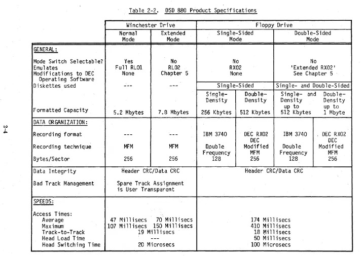
. The floppy disk system of the DSD 880 is capable of recording data in single-density using the industry standard IBM 3740 format, double frequency (FM) code as well as the double-density DEC RX02 format using the DEC-modified modified frequericy (MFM) . technique. Product specifications are given in Table 2-2.
2.4 Cable and Connector Requirements
2.5 PowerS~ecifica tions
Input Voltage 100 Vac or 120 Vac + 10% 220 Vac or 240 Vac
+"
10% 50 Hz + 1 Hz60 Hz
+
1 HzChassis Current (maximum) 120 V /60 Hz 220V /50 Hz
Busy 6A 3A
Starting Current 2SA Max @ 115 Vac 14A Max @ 230 Vac
Heat Dissipation (BTU/HR) Normal Maximum
Chassis 1055 1175
Fuse Ratings (All Slo - Blo) Main Winchester 4A @ 120 Vac 2A @ 120 Vac 2A @ 220 Vac lA @ 220 Vac INTERFACE
LSI-II PDP-II
(Q-Bus) (Unibus)
Current Consumption (+5 V)
Nominal 2.5A 2.S
Maximum 3A 3.3
Heat Dissipation (BTU/HR)
Nominal 43
Maximum 52
2.6 Ph~sical S2ecifications CHASSIS
Size Chassis 5.25 "H X 17.6''W X 23.7 4"D (13.3CM X 44.7CM X 76.2 CM) Shipping Carton 12.5"H X 24.5''W X 30.0"D
(31. 75CM X 62.2CM X 76.2CM)
Weight Chassis 56.6 Ibs. (25.7 Kg)
System Packed SO Ibs. (36.3 Kg) f or Shipping
2.7 Environmental Requirements
All disk systems manufactured by DATA SYSTEMS DESIGN perform efficiently in a normal computer room environment. Temperature, humidity, and cleanliness are three environmental considerations that can affect the reliability of diskette use.
2.7.1. Environmental Specifications TEMPERATURE
Operating
Non-Operating
HUMIDITY
ALTITUDE 2.7.2 Cleanliness
Chassis
Diskettes
Diskette Maximum Rate of Change Chassis
Diskettes Cha"ssis
Diskettes
Chassis (operating)
410F to 104°F (5°c to 40°C) 50°F to 120°F (100C to 510 C)
(150/HR)
-400F to 1500F (-400C to 660C) -400F to 1200F (-400C to 510C) 10% to 78% (non-condensing) 8% to 80%
(With a maximum wet bulb temperature of 780F (25.50C)
6000 feet maximum
Cleanliness is important wherever diskettes are to be stored, handled, and used. Store the diskettes in areas free of dust and corrosive chemicals. The storage area should also be free of strong magnetic fields which might damage the recorded data. When handling a diskette, never touch the exposed magnetic media.
GENERAL:
Mode Switch Selectable?
Emulates
Modifications to DEC
Operating Software
Diskettes used
Formatted Capacity
DATA ORGANIZATION:
Recordi ng format
Recording technique
Bytes/Sector
Data Integrity
Bad Track Management
SPEEDS:
Access Times:
Average
Maximum
Track-to-Track
Head Load Time
Head Switching Time
Table 2-2. DSD 880 Product Specifications
Winchester Drive
Normal
Extended
Mode
Mode
Yes
Full RL01
None
No
RL02
Chapter 5
5.2 Mbytes
7.8 Mbytes
---
---MFM
MFM
256
256
Header eRC/Data eRe
Spare Track Assignment
is User Transparent
47 Millisecs
70 Millisecs
107 Millisecs 150 Millisecs.
19 Millisecs
20 Microsecs
Floppy Drive
Single-Sided
Double-Sided
Mode
Mode
No
RX02
None
No
'Extended RX02'
See Chapter
5 .Single-Sided
Single- and Double-Sided
Single-Density
256 Kbytes
IBM 3740
D,.Oub
1e
Frequency
128
Double-Density
512 Kbytes
DEC RX02
DEC
Modified
MFM
256
Single- and
Density
up to
512 Kbytes
IBM 3740
Double
Frequency
128
Header eRC/Data eRe
174 Millisecs
410 Millisecs
18
~illisecs50 Millisecs
100 Microsecs
Double-Densi ty
up to
1 Mbyte
. DEC RX02
DEC
Modified
[image:18.797.32.750.44.551.2]~ I
c.n
Start/Stop Time
Nominal Rotational Speed
Average Latency
Data Transfer Rate:
Within a track
across entire disk
burst rate
Data Transfer Length
LSI-II INTERFACE
Backplane Requirement
Device Addresses:
Standard (as shipped)
Alternate**
Hardward Bootstrap
Start Address:
Standard (as shipped)
Alternate**
**Jumper Selectable
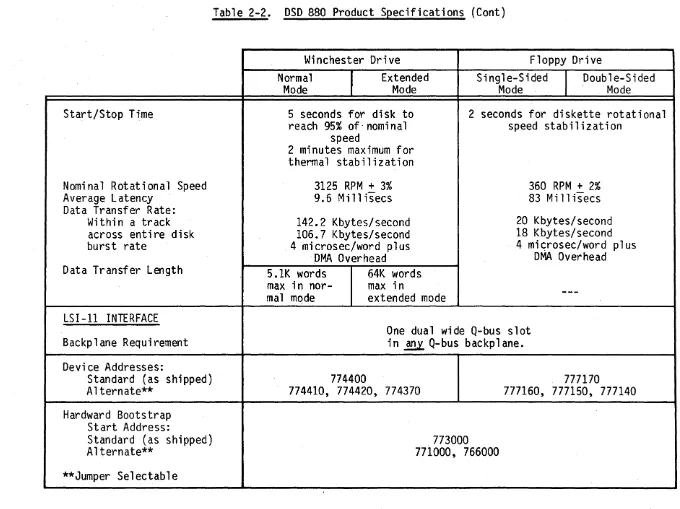
Table 2-2. DSD 880 Product Specifications (Cont)
Winchester Drive
Normal
Extended
Mode
Mode
5 seconds for disk to
reach 95% of-nominal
speed
2 minutes maximum for
thermal stabilization
3125 RPM
+3%
9.6 Mill isecs
142.2 Kbytes/second
106.7 Kbytes/second
4 microsec/word plus
DMA Overhead
S.IK words
64K words
max in
nor-mal mode
max in
extended mode
Floppy Drive
Single-Sided
I
Mode
Double-Sided
Mode
2 seconds for diskette rotational
speed stabilization
360 RPM
+2%
83 Mi
11isecs
20 Kbytes/second
18 Kbytes/second
4
mi~rosec/wordplus
DMA Overhead
One dual wide Q-bus slot
in
~Q-bus backplane.
774400
774410, 774420, 774370
773000
771000, 766000
777170
[image:19.797.47.727.53.562.2]Table
2-2.
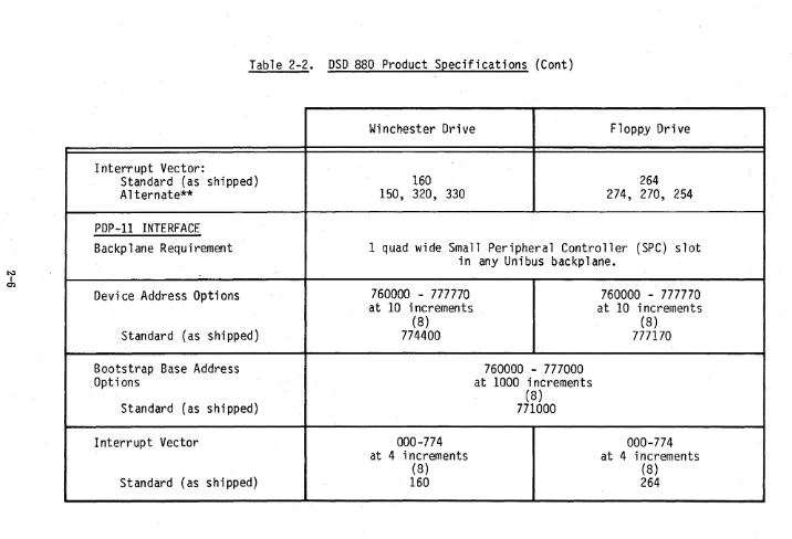
DSD 880 Product Specifications (Cont)
Interrupt Vector:
Standard (as shipped)
Alternate**
PDP-II INTERFACE
Backplane Requirement
Device Address Options
Standard (as shipped)
Bootstrap Base Address
,Options
Standard (as shipped)
Interrupt Vector
Standard (as shipped)
Winchester Drive
Floppy Drive
160
264
150, 320, 330
274, 270, 254
1 quad wide Small Peripheral Controller (SPC) slot
in any Unibus backplane.
760000 - 777770
at
10
increments
(8)
774400
000-774
at 4 increments
(8)
160
760000- 777000
at
1000
increments
(8)
771000
760000 - 777770
at
10
increments
(8)
777170
000-774
at 4 increments
[image:20.795.34.750.49.537.2]3.0 INSTALLATION
3.1 General Information
This chapter provides information on unpacking and inspection, installation, configuration; and initial check out of your DSD 880 Data Storage System.
3.2 Unpacking and Inspection
When your DSD 880 shipment arrives, inspect the shipping container immediately for evidence of mishandling during transit. If the container is damaged, request that the carrier's agent be present when the package is opened.
Compare the packing list attached to the shipping container against your purchase order to verify that the shipment is correct,.
Unpack the shipping container and inspect each item for external damage such as broken controls and connectors, dented corners, bent panels, scratches, and loose components.
If any damage is evident, notify DATA SYSTEMS DESIGN Customer Service im media tely.
Retain the shipping container and packing material for examination in the settlement of claims, or for future use. Retain the cardboard shipping disk which is installed in the flexible disk drive.
3.3 Power Requirements
The DSD 880 is available in configurations for nominal line voltages of either 120 or 240 Vac. The line frequency must be within 1 Hz (cycles per second) of either 50 or 60 Hz.
NOTE
The voltage and frequency configuration of the DSD 880 cannot be field modified.
3.4 Installing the DSD 880 Chassis
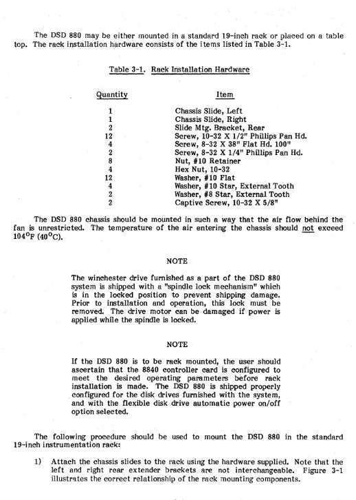
The DSD 880 may be either mounted in a standard 19-inch rack or placed on a table top. The rack installation hardware consists of the i terns listed in Table 3-1.
Table 3-1. Rack Installation Hardware
Quantity
1
1
2
12
4 2
8
4
12
4
2
2
Item Chassis Slide, Left Chassis Slide, Right Slide M tg. Bracket, Rear
Screw, 10-32 X 1/2" Phillips Pan Hd. Screw, 8-32 X 38" Flat Hd. 100" Screw, 8-32 X 1/4" Phillips Pan Hd. Nut, #10 Retainer
Hex Nut, 10-32 Washer, #10 Flat
Washer, # 10 Star, External Tooth \\lasher, #8 Star, External Tooth Captive Screw, 10-32 X 5/8"
The DSD 880 chassis should be mounted in such a way that the air flow behind the fan is unrestricted. The temperature of .the air entering the chassis should not exceed
1040F (400C).
-NOTE
The winchester drive furnished as a part of the DSD 880 system is shipped with a "spindle lock mechanism" which is in the locked position to prevent shipping damage. Prior to installation and operation, this lock must be removed. The drive motor can be, damaged if power is applied while the spindle is locked.
NOTE
If the DSD 880 is to be rack mounted, the user should ascertain that the 8840 controller card is configured to meet the desired operating parameters before rack installation is made. The DSD 880 is shipped properly , configured for the disk drives furnished with the system, and with the flexible disk drive automatic power on/off option selected.
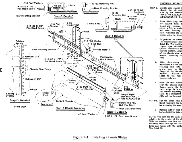
The following procedure should be used to mount the DSD 880 in the standard I9-inch instrumentation rack:
#10 Flat Washer
#10-32 X 1/2- " \
nt:J---10-32 Retaining Nut
Pan Head scre~~-.
~~~~
IT I r R e a r , Mounting Bracket
l!' L - #10-32 X
1/2-I 3 10-32 Pan Head
, JRe,aining Nu' #10
Fla,,:?
lJ31
Rack Washer7
ChaSis
:'~:~_~ lSl~s~~~s~ii~'
Rear Mounting Bracket Step-5 Detail-D
# 1 0 Flat
J-
1 0-3~# 10-32 X 112- _ Washer Retainer Nut Pan Head
screw~\
' " ' " ' '~
,~'@ Step-4 Detail-C
Rear Mounting Bracket
~,~' , f,
)
---1 ~~inimum 3/8"
; 'IT-'t
I ' -,
#10-32 X 1/2"
(Jl;,~~'
~
"-Pan Head Screw Washer ~'~ Rack
\ )
:a:~-y
:~-~Chassis
Slide Flange/::::::--
-:/~ ~",,- , / 3/8 n1000 ~ ~
I
I
I
"'-- '~~ ~18-32 X
~,~.~ "-" Flat Head~ I
/ / I ~ ",--Screw ~
( I ~/' ,. ~ ~',>,
!
I <' ~ In~er ~I ~~ Safety'> Shde
I
I ,0:-,\ 1 0-..1
1
) : ~ Minimum 2 114"
~ ~:
IIJ
...
'''~.~~
L._J
\(-,
Existing~ System
I Stop , /
o /' " <. > " L 8-32 PEM Nut
~/RaC(k ~b~. / ' "-~Of Chassis"
FOO'~
"-Step-3 Detail-8 [ ________ Cabinet Chassis ~ See Note 2 ' - - - - __ Front View
Step-2 Chasis Mounting
#8 Star Washer
... ~
See
Detail A '
-... -
/>
Flange, Right , Side (Part Of ...,/ PIN XXXXXX-02)
Screw Mtg PEM Nut (Far Side)
Rivet Clearance Hole
Step-1 Detail-A
8-32 X 114 Pan Head Screw
ASSEMBLY INSTRUCTIONS
STEP-I. Unpack your chassis slide kit and identify the right and left chassis slide by the stamped part no: Left is PIN XXXXXX-oI, Right is PIN XXXXXX-02. (See detail-A.)
2. After identifying the right and left chassis slides (see chassis mounting), remove the inner slides by fully extending the slides and then releasing the safety stop. Assemble the inner slides to chassis using the fasteners shown. 3. To position the chassis slides, use
the recommended dimensions (see detail-B). The positioning is con-tingent upon mounting your new system underneath or above the existing system. Align the flange of the chassis slide with the two nearest mounting holes of the rack.
4. After determining which two holes/slots will be used, slide the retaining nuts into the appro-priate slots on the mounting flange of the chassis slides (see detail-C). Fasten the chassis slides to the rack using the fasteners shown •
5. Slide the rear mounting bracket over the chassis slide until the flange meets the back of the rack. Align the bracket with the two nearest mounting holes on the rack. It is important to keep the slide and rear bracket level.
NOTE-I. For the extra long racks, adcli-tional hardware has been supplied for stiffening the assy.
2. Remove rubber feet from system before installing into rack.
NOTE: The rear has the same slot spacing relative to the center of the chassis slide. Slide the retainer nuts into the appropriate mounting slots, re-align the bracket to the holes and fasten with the hardware shown. (See detail-D)
[image:23.799.47.687.63.562.2]2) Insert the DSD 880 into the chassis slides and push the unit into the rack. 3) Remove the front bezel from the DSD 880 and install the retaining screws.
4) Replace the bezel by locating the guide pin and pressing firmly until the retaining mechanism engages firmly.
3.5 Interface Module and Cable Installation
3.5.1 Preparation
WARNING
• Ensure that system power is off before installing the interface module and cable.
• Ensure that system power is off before changing the interface switch positions.
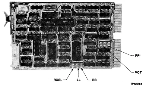
The DSD 880 LSI interface card is a dual width card, labeled PIN 808832. The DSD 8832 is shown in Figure 3-2.
PAl
VCT
TP102/81
[image:24.613.58.552.403.692.2]Switch Location
1 E -
2E--"""'-RL Disable
Boot -Disable
Switch Location
1A
2A
-3A--~
RX Disable
TP 103/81
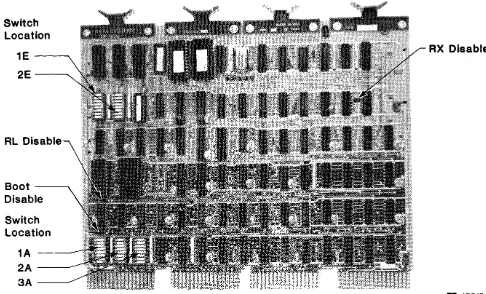
Figure 3-3. DSD 8830 Computer Interface Card
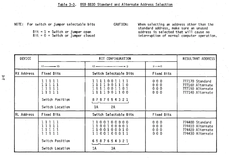
The DSD 880 PDP-11 interface card is a quad-wide card, PIN 808830. The DSD 8830 is shown in Figure 3-3.
The DSD 8832 interface card provides for both the winchester and floppy disk selection of one of four device register addresses, one of three bootstrap PROM (programmable read only memory) starting addresses, and one of four interrupt vector addresses. The DSD 8832 also allows the user to disable the RX02 and bootstrap response, enabling the user to supply his own.
Table 3-2 lists the standard and alternate addresses for the device registers and the bootstrap PROM's starting addresses. The DSD 8832 is shipped in the standard configura tions.
It should be noted that the switch position number referred to in Table 3-2 indicates the number on the PCB Board silk screen.
The DSD 8830 interface card can emulate both RX02 and RL01 device registers according to DEC standards. Since the 880 controller can only operate on one device at a time, the 8830 arbitrates between sending the latest RL command and the latest RX command without violating device register protocols. An onboard bootstrap eliminates the need for a DEC bootstrap board. Finally, five switch packs allow the user to select any of the possible boot addresses, device register addresses, or vector addresses.
[image:25.626.64.550.68.362.2]Table 3-2. DSD 8832 Standard and Alternate Address Confi uration Re er to Figure 3-2 for Jumper Location
Switch/Jumper
RXSL (RX Device) 01234 OOOOS OOOSO OOSOO OSOOO SOOOO
LL (RL Device) 01
00 OS SO SS
BB (Boot Base) 01
00 OS SO SS
V CT (RX Vectors) 1234
-00 -OS -SO -SS
00- (RL Vectors)
OS- SO-
SS-PRI (RLOI Priority) 4321
SSSO SSOS SOSS OSSS
S
=
Shorto
=
Open -= NANOTE
Address
177150 Alternate 1 77140 Al terna te 177160 Alternate 177170 Standard RX Disable
774410 Alternate 774420 Alternate 774370 Alternate 774400 Standard
166000 Alternate 171000 Alternate Boot Disable 173000 Standard
274 254 270 264 150 330 320 160 PRI7 PRI6 PRJ 5 PRJ 4 Alternate Alternate Alternate Standard Alternate Alternate Alternate Standard Standard Alternate Alternate Alternate
Table 3-3. DSD 8830 Standard and Alternate Address Selection
NOTE:· For switch or jumper selectable bits
Bit
=
1
=
Switch or jumper open
Bit
=0
=Switch or jumper closed
·CAUTION:
DEVI CE
BIT CONFIGURATION
17 • 13 12 .. 3
RX Address
Fixed Bits
Switch Selectable Bits
1 1 1 1 1
1 1 1 100 1 1 1 1
11111
1 1 1 1 001 1 1 0
1 1 1 1 1
1 1 1 1 001 101
1 1 1 1 1
1 1 1 1 001 100
Swi tch Pas i ti on
8 7 876 543 2 1
L-..J' I
Swi t ch Locati on
1A
2A
RL Address
Fixed Bits
Switch Selectable Bits
1 1 1 1 1
1 1 001 0 0 0 0 0
1 1 1 1 1
1
1
001 0 0 001
1 1 111
1 1 001 000 1 0
1 1 111
1 ·10 0 1 0 0 0 1 1
Switch Posi ti on
6 5 876 543 2 1
L-...JI I
Switch Location
1A
3A
When selecting an address other than the
standard address, make sure an unused
address is selected that will cause no
interruption of normal computer operation.
RESULTANT ADDRESS
2 - 0
Fixed Bits
000
777170 Standard
000
777160 Alternate
000
777150 Alternate
000
777140 Alternate
Fixed Bits
000
774400 Standard
000
774410 Alternate
000
774420 Alternate
[image:27.794.34.766.59.572.2]C/.j
I 00
DEVICE
Boot Address
RX Vector
RL VECTOR
Table 3-3 .. DSD 8830 Standay'd and Alternate Address Selection (Cont)
BIT CONFIGURATION
RESULTANT ADDRESS
Fixed Bits
Switchable Bits
Fixed Bits
1 1 1 1 1
100 1
000 0 0 0 0 0 0
771000 Standard
1 1 1 1 1
101 0
o
0 0 0 0 0 0 0 0
772000 Alternate
1 1 1 1 1
1 1 0 1
o
0 0 0 0 0 0 0 0
775000 Alternate
1 1 111
1 1 1 0
o
0 0 0 0 0 0 0 0
776000 Alternate
Switch Posi ti on
4 3 2 1
I I
Swi tch Locat ion
lA
Fixed Bits
Switchable Bits
Fixed Bits
o
0 0 0 0 0 0 0 0
o
1 0 1 101
o
0
264 Standard
000000000
o
1 0 1 100
o
0
260 Alternate
o
0 0 0 000 0 0
o
1 0 1 011
o
0
254 Alternate
o
0 0 0 0 0 0 0 0
o
1 001 1 0
o
0
230 Alternate
Switch Position
7 6 5 4 3 2 1
I - - . . J
Switch Locati on
IE
Fixed Bits
Switchable Bits
Fixed Bits
o
0 0 0 0 0 0 0 0
0011100
o
0
160 Standard
o
0 0 0 0 0 0 0 0
001 101 1
o
0
154 Alternate
o
0 000 0 0 0 0
001 101 0
o
0
150 Alternate
o
0 0 0 0 0 000
001 1 001
o
0
144 Alternate
Switch Positi on
7 6 543 2 1
I ----.J
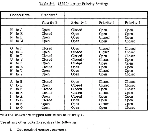
Table 3-4.8830 Interrupt Priority Settings
Connections Standard*
Priority 5 Priority 4 Priority 6 Priority 7
N toJ Open Closed Open Open
N to K Closed Open Open Open
N to L Open Open Closed Open
N to M Open Open Open Closed
0 to P Closed Open Closed Closed
Q to R Open Closed Closed Closed
S to T Closed Closed Open Closed
U to V Closed Closed Closed Open
W to P Open Closed Open Open
W to R Closed Open Open Open
W to T Open Open Closed Open
W to V Open Open Open Closed
A to B Closed Open Closed Closed
C to D Open Closed . Closed Closed
E to F Closed Closed Open Closed
G to H Closed Closed Closed Open
I to A Open Closed Open Open·
I to C Closed Open Open Open
I to E Open Open Closed Open
I to G Open Open Open Closed
*NOTE: 8830's are shipped fabricated to Priority 5. Use at any other priority requires the following:
1. Cut required connections open.
2. Insert .025" square wire-wrap pins at appropriate connection points • . 3. Wire wrap required connection closed.
Table 3-5. 8830 Jumper Configurations
8830 jumpers are shipped configured fora standard configuration where RX, RL, and BOOT are enabled and RXCS address bit is fixed at D.
Jumper Function In Out Shipped
Number Location
1-2 13E RXCS address bit 2 0 1 or 0 In
3-4 13E RX Disable Disable Enable Out
5-6 lC RL Disable Disable Enable Out
[image:29.620.71.554.63.491.2]3.6 AC Power Cord Installation To install the ac power cord:
A. Ensure that the DSD 880 power on/off switch is in the 'off position.
B. Plug the female end of the power cord into the connector on the back of the DSD 880 chassis.
C. Plug the male end of the power cord into an ac power receptable that provides the proper ac input voltage for the DSD 880 (90 to 130 V rms, on domestic models, or 198-250 V rms on international models configured for the higher voltage.)
3.7 Initial Checkout and Acceptance Testing
After installation of the DSD 880, an initial power-up and testing sequence should be completed prior to placing the system into regular service. Be sure the winchester spindle lock has been removed prior to operation. DSD recommends the following procedure be followed:
NOTE
Prior to applying power and performing acceptance testing, the operator should familiarize himself with the normal operating procedures of Chapter 4 and the use of DSD HyperDiagnostics tests in Chapter 7 of this manual.
A. Remove the DSD 880 front bezel by grasping the bezel and pulling forward. Removal of the front bezel will allow access to the Hyper Diagnostics panel.
B. Assure either that power is applied to the host computer, or that the interface cable is not connected.
C. Apply power to the DSD 880 using the power on/off switch on the rear panel of the chassis.
c...
~'f'":tro£ffiA·-t g t"y
D. Insert a blank, write enabledj1floppy disk into the floppy disk ·drive.
NOTE
E. Perform the DSD 880 HyperDiagnostic Switch and Light Test using the procedure that follows:
1. Place the FLOPPY and WINCHESTER WRITE PROTECT switches in the OFF position, select MODE
=
3, CLASS=
0 and depress the EXECUTE pushbutton. Verify that 30 is displayed by the 7 segment displays.2. Observe the FAULT, WINCHESTER READY, FLOPPY FAULT, WINCHESTER FAULT, and FLOPPY WRITE PROTECT indicators. Verify that each illuminates and extinguishes independently of the other indicators before proceeding.
3. Rotate the MODE switch through positions 0 - 7, verify that the switch position is displayed by the left digit of the 7 segment displays. 4.. Rotate the CLASS switch through positions 0 - 7, verify that the
switch position is displayed by the right digit of the 7 segment displays.
5. Place the FLOPPY WRITE PROTECT switch in the ON position, verify that the FLOPPY WRITE PROTECT and FLOPPY FAULT indicators illuminate, and that the value 88 is flashing in the 7 segment displays.
6. Place the FLOPPY WRITE PROTECT switch in the OFF position and the WINCHESTER WRITE PROTECT switch in the ON position. Verify that the WINCHESTER. WRITE PROTECT and WINCHESTER FAULT indicators illuminate, and that the value 99 is flashing in the 7 segment displays.
7. Place the WINCHESTER WRITE PROTECT switch in the OFF position.
F. If no malfunctions are detected during the 880 Switch and Light test, perform the DSD 880 HyperDiagnostic Sequential Scan Floppy Disk (50) and Sequential Scan Fixed Disk (54) tests as given in Section 7 of this manual.
G. . Select the desired normal operating mode and class (see Table 4-2), then depress tne Execute pushbutton momentarily. The selected mode and class will be displayed while the execute pushbutton is depressed. Upon release of the Execute pUshbutton, verify that the code 0.0. is displayed, indicating that both the floppy and winchester drives were successfully initialized. H. Reconnect the interface cable and apply power to the host computer if
necessary.
3~8' DSD 880. Initial Program Installation
This section provides a description of the DSD supplied software available and guidance in the integration of the DSD 880. into the user's operating system.
3.8.1 DSD Supplied Programs
The DSD 880. is shipped from the factory preformatted with bad track and bad sector file information on the winchester. A floppy diskette is included which contains the DSD supplied programs and command files. Several of these programs are also shipped on the winchester as an aid in initial testing of the DSD 880.. Appendix A contains a directory listing of these devices/diskettes.
The main progm.ms supplied are:
FLPEXR - a stand alone diagnostic/utility program for operations on the floppy drive. See Appendix C.
FIXEXR - a stand alone diagnostic program for operations on the winchester drive in RL emulation mode. See Apendix D.
SATEST - a stand alone diagnostic/utility program for operations on the winchester drive in direct access mode and for disk formatting and bad track mapping. See Appendix E.
3.8.2 Command Files
Command files are supplied for the main operations necessary to utilize the extended features of the DSD 880 and to assist the user in the initial loading of the operating system onto the DSD 880. A full listing of each command file is contained in Appendix B of this manual. Usage of each command file is described in the appropriate section of the manual.
Command files are also provided to facilitate backup and restores of the DSD 880 winchester. These command files should be considered as representative only; individual users should tailor the commands to their particular needs. These files are called 88XFLP.COM, FLPX88.COM.
3.8.3 Use of DSDMON
DSDMON is the DSD diagnostic monitor program that allows the user to select which diagnostic program is to be executed from the distribution diskette. It is a secondary bootstrap program that loads RT-ll format files into memory and initiates execution of that program. Although DSDMON accesses files through an RT-ll type format, RT-ll is not required to run DSDMON.
To initiate a program, boot the diskette through the hardware bootstrap procedures. The program will output on the console:
DSD DIAGNOSTIC MONITOR PROGRAM V3A DSDMON>
The program to be initiated is specified by typing: R filename <CR>
DSDMON assumes an extention type of .SA V. If the file is not found on the diskette, DSDMON will output:
FILE NOT FOUND
If the file is found on the diskette, it will be brought into memory and execution begun. DSDMON also supports the following commands:
T filename <CR> H <CR>
R filename<CR> L filename<CR>
Types the specified file contents on the console terminal
Types a Help file on the console terminal Load and Run specified progra m
DSD supplied diagnostics are configured such that, if they are initiated from an RT-11 system, control can be returned to RT-11. If invoked from DSDMON, they will still prompt for "RETURN TO RT-l1 ?", however, such return is not possible and a Y (yes) reply will cause the diagnostic to be reinitialized. In order to run a different diagnostic, DSDMON must be booted again. DSDMON can be restarted at the last location in memory (for a 28KW system, this address is 157776).
3.8.4 Transfer of RT-11 to DSD880
A. Transfer of RT-11 V 3B to the 880 winchester:
1. Procure a DY bootable RT-ll distribution diskette with a DL handler (DL.SYS) on it.
2. Boot this diskette and prepare to copy all files onto the 880 winchester.
NOTE
The 880 winchester as shipped contains an RT-l1 directory and all the DIAGNOSTIC DISKETTE files. These may be retained by skipping the following step. INIT DLO:/NOQ<CR>
3. Copy all the RT-l1 files on the distribution disk onto the 880 winchester. COpy /SYS DYO:*. * DLO:<CR>
4. If the boatable RT-11 V3B distribution diskette does not contain a DL monitor, then it must be copied from one of the other distribution diskettes (#2 or #3).
This can be done most easily if another device is available to use as a system device. If only the DSD 880 is available, then proceed as follows: a) .SET USR NOSWAP <CR>
.R DIR<CR>
*
Remove the bootable system disk.
Write protect the floppy drive using the front panel switch. Insert the other distribution disks one at a time and type.
*DYO:/B/E <CR>
Example:
DLMNSJ.SYS 74 150
Where 74 'is the length and 150 is the starting block number. 5. Make the 880 winchester hardware bootable:
COPY/BOOT DLO:DLMNSJ.SYS DLO:<CR> COPY/BOOT DLO:DLMNFB.SYS DLO:<CR>
or
Remove the distribution disk containing DLMNSJ.SYS. Reinsert the bootable disk first booted on.
Unprotect the floppy drive using the front panel switch. Type: <CTRL C>
.LOA DL:<CR> .R DUP<CR>
*DLO:DLMNSJ.SYS=/C:4000.:64.<CR>
*DLO:A=DYO:/I: (starting read block):(starting read block & length of file):(starting write block)=4000.
For example, with the starting block and length given in the directory example:
*DLO:DLMNSJ.SYS/I:150.:214.:4000.IW<CR> The system will ask "CONTINUE?"
Remove the bootable system disk and insert the diskette containing DLMNSJ.SYS found above.
Type: Y <CR>
The syste m will copy the blocks specified on the 880 winchester and type: "INSERT SYSTEM DISK, ARE YOU READY?"
Remove the other distribution diskettes and insert the bootable system diskette.
Type: Y <CR>
There should now be a copy of the DL monitor (DLMNSJ.SYS) on DLO. 3.8.5 Transfer of RT-ll V 4 to the 880 Winchester
1. Boot the bootable distribution diskette in DYO:.
NOTE
The DSD 880 winchester is shipped with a copy of the DSD diagnostic disk on the winchester.
These contents may be retained by skipping the following step: Type: INIT DLO:/NOQ<CR>
3. Copy all files from the floppy to the 880 winchester • . COPY/SYS DYO:*.* DLO:<CR>
4. Bind the device monitor to the DL handler to make it bootable • • COPY/BOOT DLO:RT11SJ DLO:<CR>
5. Bootstrap the RT-11 on the 880 winchester • • BOOT DLO:<CR>
3.8.6 Double-Sided Support Under RT-11 (Version 3B)
Double-sided support under RT-11 V38 may be "activated" by one of two methods. DSD supplies a software device handler which is equivalent to the DEC device handler with appropriate flags and conditionals enabled for double-sided support. This handler may be assembled into the RT-ll DY monitor (FB or SJ) by following the system generation procedure as supported by DEC. Alternately, to save the effort required to perform a SYSGEN, DSD supplies a command file which will automatically patch the RT-11 V3B monitor to activate the two sided features.
If the user elects to perform a SYSGEN, the DSD handler DYDSD.MAC (found on the DSD diagnostic diskette) must first be renamed to DY.MAC and SUbstituted for the MACRO-11 source file, DY.MAC provided by DEC. The DSD handler, containing double sided support may then be installed into the RT-11 monitor by following the procedure described in the RT-11 System Generation Manual supplied by DEC.
Note that the actual monitors (DYMNSJ.SYS or DYMNFB.SYS) must reside on side 0 in order to boot initially.
DOUBLE SIDED SUPPORT UNDER RT-11 V3B A. N onsystem for side 1.
The file DYDSD.SYS on the diagnostic disk is an RT-11 V3B handler compatible with the distribution kit monitors that can be copied over to the winchester for use.
1. Boot RT-11 V 3B on the 880 winchester.
3. Copy the RTV 3B DY handler over to the winchester . • COPY DYO:DYDSD.*/SYS DLO:DY.*<CR>
4. Reboot the DL monitor • • BOOT DLO:<CR>
This installs the double sided handler.
3.8.7 The DSD Monitor Patch Program For RT-ll V3B
The Monitor Patch Program takes a DYMNSJ or DYMNFB monitor from the DEC RT-ll V3B system distribution and replaces the DY handler currently in the distribution monitor with a double sided DY handler. The new monitor has the same characteristics as the original monitor, such as batch support, 60 Hz line time clock, all handlers supported by the distribution monitor, and no error logging.
The monitor patch program would be used under the following conditions:
1. The distribution RT-ll V3B monitor provided by DEC is sufficient for the user's normal applications, except for not having double sided support.
2. The user does not wish to perform a System Generation.
3. The user has not changed the normal distribution monitor with customized patches, relating to the the user's system.
If these conditions are not met, a System Generation may be required.
The DYMNSJ or DYMNFB monitor may be generated from the first or second release of RT-ll V3B. The distribution DYMNSJ or DYMNFB monitor that will be modified can be found on the distribution diskette shown below:
First DX KIT Release of RT-l1 V3B DYMNSJ.SYS
DYMNFB.SYS
Second DX KIT Release of RT-ll V 3B DYMNSJ.SYS
DYMNFB.SYS
or either DY KIT release may be used.
Disk Label No. AS-5781B-BC AS-5781B-BC Disk Label No. AS-5783C-BC AS-5783C-BC
To use. the DSD monitor patch procedure on the DSD 880:
Dated 11-l\1ar-78 Il-Mar-78 Dated 27-Mar-79 27-Mar-79
2. Copy the desired DY monitors from the DEC floppy distribution kit onto the 880 winchester (DYMNSJ.SYS and DYMNFB.SYS).
3. Copy the PAT files from the DSD diagnostic diskette onto the winchester. Insert the diagnostic diskette and type:
.@DYO:PATSET<CR>
4. Put a blank diskette in DYO: and set to double density. Note: the DEC format program only supports the standard device addresses. Use DSDFMT if an al terna te address is to be used •
• R FORMAT *<CTRL C>
5. Determine which double sided monitor is to be generated. Type: .@PATSJ<CR>
to put a single job monitor on DYO: or type: .@PATFB<CR>
to put a foreground/background monitor on DYO:.
, Note: Both steps 4 and 5~hould be repeated if both double sided monitors are to be created.
This procedure will copy a minimal system over to the floppy in DYO:, then patch the monitor and then boot that monitor. This diskette then contains the selected RT-ll V 3B monitor with double sided support and should be used as a master for generating other double sided bootable diskettes.
NOTE
RT-l1 V3B will not boot a floppy with the selected monitor on the second side.
3.8.8 Double Sided Floppy Support Under RT-ll V 4
A command documentation file DYV 4DS.DOC is provided which applies the difference to the DEC distribution DY.MAC given in DYV 4DS.DIF.
To update the RT-l1 V 4 DY handler: 1. Boot up RT-l1 on the 880 winchester.
3. Copy DY V 4DS.
*
from the DSDdiagnostic disk onto the winchester. 4. Type @DYV4DS.DOC.An updated DY.SYS and an updated handler source DYV 4DS.MAC will be generated. This handler includes full double sided support and allows booting with the syste m files on side one •.
3.8.9 Extended Mode Winchester Support
The DSD 880 operates in either RL01 compatible mode or extended mode which is a subset of an RL02. No changes to the RT-11 system are required to use the RL01 compatible mode. By using the RT-11 FILE.BAD capability to mask the unavailable disk area, extended mode can also be used without any operating system patches. If the FILE.BAD approach is not acceptable, then only a few minor patches to the DL handler will allow the extended mode operations.
Command file DL V 388 .DOC contains the procedures to be followed to enable extended support for RT-ll version 3B. For RT-11 version 4, command files DL V 488.DIF and DLV 488.DOC contain the changes to be applied to the RT-11 distribution handler sources using the SLP program.
3.8.10 Transfer of RSX-IIM to DSD 880 Winchester
In order to bring up RSX-11M on the DSD 880, a host machine capable of reading the DEC distribution kit is required. There are several methods of transfer from this machine/disk onto the DSD 880:
1. SYSGEN with DSD 880 attached as an RL01/2 to the host machine. 2. SYSGEN with floppy drive and RL01/2 attached to the host machine.
3. SYSGEN on host system with only floppy drive available as an intermediary device.
The remainder of this section describes these methods in more detail. SYSGEN with DSD 880 attached as an RL01/2 to the host machine
This is the most convenient method in that standard SYSGEN procedures can be followed for generating a target system. If the DSD 880 is in extended mode the host monitor device size table should be updated before running BAD and INIon the DSD 880. (See RSX-IIM extended support section for details.)
,SYSGEN with floppy drive and RL01/2 attached to host machine
3.8.11 RSX-11M Double Sided FioDPY Support
RSX-11M as distrlbuted has almost all the support needed for RX03 type floppy systems. There are, however, some glitches which are detailed below and in command file RSX11 M.DOC.
1. BUG in extended memory cross field transfers. This is documented in the June 1980 SOFTWARE DISPATCH. The correction is also contained in the file RSX11M.QOC on the DSD distribution diskette.
2. BUG in track/sector calculation algoritm in 11,10 DYDRV.MAC and 12,10 SA VSPC.MAC used in 1,20 or 1,24 SA V.OLB. This causes a hard error return from the handler whenever block numbers (double density, double sided) greater than 1664 are accessed. A fix for the handler is included in file RSX11M.DOC on theDSD distribution diskette. If the SA V .OLB is not rebuilt prior to SYSGEN then any tasks that SA V accesses when saving the RSX-11M system image must reside below block 1663. If not, it will be impossible to make a floppy bootable RSX-11M system image.
3.8.12 RSX-11M DSD 880 Extended Suppport
The DSD 880 operates in either RL01 compatible mode or extended mode which is a subset of an RL02. The RSX-11 monitor must be informed of this difference in device sizes in RL02/extended mode.
The system keeps a record of device sizes in the Unit Control Block (UCB) at the word offset (U.CW2,U.CW3) relative to the UCB entrance .DLx (.DLO or .DL1) depending on the logical unit number. The default value of 10240. (= 24000 octal) is placed at that location at SYSGEN time. This corresponds to an entire RL01 disk pack. This value is accessed during INI, BAD and SA V functions and is doubled before use if the device is an RL02 instead of an RLO 1. Thus to initialize a DSD 880 in extended mode, the value of one half the size of the extended disk (7776. = 17140 octal) should be entered into U.CW3 for the 880 winchester unit.
If a SA V is done onto an RL02, the doubled value is left in U.CW3 and will be seen whenever that system image is booted (refer to DLSET: in 12,10 SA VSUB.MAC). Therefore, the U.CW3 value should be mOdified using PATCH and the SYSTEM MAP
before doing the final SA V
/WB
command. 'If RT-11 Version 4 is available, generate a system supporting the RL01/2 and floppy drive •. Bring up this RT-11 system. Copy the RSX system image (on RL01/2) out onto multiple floppies then onto the DSD 880 using the RT-11 V 4 indirect command files provided (8'8XFLP.COM and FLPX88.COM) on the DSD distribution diskette. After these diskettes are copied onto the DSD 880, the DSD 880 will contain an image copy of the
original RL01/2 and can be hardware booted into RSX-IIM.
SYSGEN on host system with only floppy drive available
This method requires generating a floppy diskette containing a RSX-11M system which is then booted using the DSD 880 floppy drive to produce an operational floppy based RSX-11M nucleus. The DSD 880 winchester drive is then setup from this nucleus and booted. The floppy can then be used to transer the remaining files onto the winchester.
This procedure is most easily done in one SYSGEN if both floppy drive and RL01/2 handlers are set as loadable. This allows the final usable RSX11M.SYS images to be brought up by simply interchanging the LOA DL: and LOA DY: commands to VMR.
NOTE
The handler for the physical volume to be VMR'd upon must be the first file structured handler to be loaded. If not, then when tasks are to be installed, the message
INSTALL DEVICE NOT LBO:
will be output independent of any assignment com-mand.
This procedure requires either a double-sided, double-density diskette on the DSD 880, or two single-sided, double-density diskette/drives.
The following are the minimum complement of files required for DL volume initialization: (602. blocks total)
RSX11M.SYS FCPMD1.TASK COT.TSK INI.TSK BAD.TSK UFD.TSK MOU.TSK MCR.TSK LOA.TSK PIP.TSK DYDRV.TSK DYDRV.STB DLDRV.TSK DLDRV.STB.
258. blocks 62.
24. 34. 50. 7. 24. 28. 29.
69.
5. 1. 4. 1.
The following files are required for the VMR phase and can be copied over individually as necessary.
RSX11M.STB RSXIIM.TSK LDR.TSK
11. blocks 130.
TTDRV.TSK TIDRV.STB SA V .TSK BOO.TSK INS.TSK
VMR.TSK IND.TSK
18 ..
5. 65. 22. 27. 142.
101.
Appendix A contains a directory listing of a double-sided, double-density floppy diskette that includes all files needed for both booting from the DY: and the final V MR of the DSD 880 winchester.
Once the DL volume is initialized and UFDs have been created, additional files can be transfered from the floppy to the winchester as necessary. Appendix B contains a command files to perform this transfer (DLRSX.CMD, DYRSX.CMD).
When the files are transferred onto the winchester, install VMR and IND, then perform the final V MR phase. Appendix B contains command files to setup and perform the VMR (DLSYSV.CMD, DYSYSV.CMD).
4.0 OPERATION
4.1 General Information
This chapter provides information on the operation of the DSD 880 Data Storage System. Included are operating parameters, mode/class selection, system initialization, bootstrapping, diskette formatting, and backup operation.
4.2 Power On Self Tests
When power is applied to the DSD 880, the controller automatically performs four self-tests:
a. ALU Test
c. CRC Logic Test
b. Internal RAM Memory Test d. PLL Test
If any of these tests fail, an error code will be displayed on the Hyper Diagnostics panel identifying the failure. If the tests are successfully passed, both the floppy disk and winchester drives are homed. The winchester drive will be write-protected for 2 minutes following a power on to allow thermal stabilization and the Winchester Ready Light will flash during this period. It is possible to read or boot from the winchester drive during this period.
4.3 Mode and Class Selection
Rotary Eight Position Mode Selection Switches
Easy Access Voltage Test Points
Indicator Floppy Activity LED: (Located on the floppy disk drive front bezel) Winchester Drive
Ready LED:
(V isible wi thou t re-moval of front bezel)
Execute Button
Seven Segment LED Displays
System Status Display Bars
LED
Indicators
Write Protect Switches
TP 104/81
Figure 4-1. DSD 880 HyperDiagnostic Panel
Table 4-1. DSD 880 Indica tors
Purpose
This indicator illuminates whenever the head of the floppy disk drive is loaded. If the drive has a door lock mechanism, the door will be locked
when the head is loaded.
This indica tor has several modes of operation. a. The indica tor will flash for
Table 4-1. DSD 880 Indicators (Cont)
Indicator Purpose
Floppy Write Protect LED:
Winchester Drive Write Protect LED:
(Visible without removal of front bezel)
Fault LED:
(Visible without removal of front bezel)
Floppy Error LE D:
Winchester Error LED:
b. Approximately 2 minutes after power is applied to the unit the indica tor will stop flashing and re main illu mina ted, if the bad track map has been read successfully, indicating that the drive is fully operational.
c. Each time the winchester drive is accessed via a read or write command the indicator will flicker, indicating that the drive is busy (not ready).
d. If a drive fault occurs which causes the winchester disk drive to be inoperative, the indicator will be extinguished until the fault is cleared.
This indicator is illuminated whenever the floppy disk drive is write protected, either by the write protect switch on the front panel, or by the presence of a write protected floppy disk •.
This indica tor is ilIum ina ted whenever the winchester disk drive is write protected by the write protect switch on the front panel.
This indicator flashes for approximately 1 minute after an error occurs during the execution of a command. After approximately 1 minute, the indicator will cease flashing and illuminate steadily until the current error is cleared. If another error occurs before the original error is cleared, the indicator light will again flash for approximately 1 minute from the occurrence of that error. The indicator will be immediately extinguished by a bus initialize from the host processor.
This indicator flashes whenever the error being displayed by the 7 segment displays occurred on
the floppy disk drive.