© 2019, IRJET | Impact Factor value: 7.211 | ISO 9001:2008 Certified Journal | Page 1
FPGA Based Processor for Feature Detection in Ultra-Wide Band Radar
Kunal K. Kadam
1, Dr. Surendra J. Bhosale
21
MTech Electronics, Electrical Department, VJTI, Mumbai-400019, India.
2
Associate Professor, Electrical Department, VJTI, Mumbai-400019, India
---***---Abstract
—UWB is radio technology making the use of short pulses and having large bandwidth and low energy which helps in finite time resolution. An algorithm is developed for signal processing of UWB radar in this work. This work also makes use of Field programmable gate array (FPGA) which is suitable for fast and parallel signal processing. High resolution can be achieved using multi-channel ADC and delay method. This time delay methods also helps in controlling high speed ADC.Keywords—Analog to digital converter, Signal processing, Field programmable gate array, Ultra-wide band signals.
1. INTRODUCTION
UWB is operated in the range of the 3-10 GHz. The advantages of UWB are high data rate, large bandwidth, less complexity and low cost. Low power spectral density occurs due to wide bandwidth during transmission of UWB, and hence possibility of interference due to another user is low. This advantage enables highly accurate measurements at short distance. UWB signals can pass through the objects that are likely to reflect signal such as doors, windows, walls. Compared to sine wave, accuracy of UWB signals is very high.
UWB Radar is capable of providing transmitting power of about 1 watt and centre frequency of 6 GHz. Range resolution of 0.1125m can be obtained. Pulse width and Pulse Repetition Frequency are 750psec and 10 KHz respectively. Normal range of 30 meter and maximum unambiguous range of 15 Km is achievable. Bandwidth of the system is large up to 2 GHz. [1].
Human trapped in the earthquake and fire disaster site uses UWB radar [2]. Frequency time analysis Hilbert Haung Transform is obtained using finite difference time domain algorithm followed by 2D FFT for spectral analysis and suppressing noise frequency component. This brings out separation of cross range data and the data extracted for breathing and heartbeat frequencies over natural frequencies. Detailed features of the Human respiratory system can be studied using UWB radar design [3].Modified raised cosine waveform (MRCW) and iterative search
correlation algorithm provides extraction of extra
information about respiratory system. This system can
detect heart rate up to frequency 0.1 to 1 Hz. Proposed algorithm can detect CZT frequency component and used to detect FSLW respiration model which includes Respiration rate, inspiration speed, expiration speed, respiration system and respiration holding ratio.
Different purposes that can be served by UWB radar are: monitoring the rail road crossing at the unmanned railway gates, removal of clutter effect using positive variation, monitoring heart beat and respiration using non-invasive manner which do not involve any instrument inside body, four TX-RX UWB sensors transmits the collected data to centralized server [4].
2.HARDWARE DESIGN
The essential hardware for the signal processing of UWB radar is described in above figure. Pulse or the reflected echoes from the target serves as input to the system. This input is then processed using amplifier, power divider, delay line, ADC and FPGA. The result from this processing will give feature detection and discrimination of the target.
Fig.1-Block diagram description reception & processing of signal of UWB radar
2.1 Amplifier:
© 2019, IRJET | Impact Factor value: 7.211 | ISO 9001:2008 Certified Journal | Page 1159
helps in amplifying low level signals at the input. In order to raise power of input signal Gallium Arsenate FET transistor is used. Such amplifier is capable of giving gain up to 16 dB and output in the range 44-46 dBm.
2.2 Power Divider:
Power division block divides the power of input signal into 8 equal parts. The ADC channel and delay line are then operated using power supplied by power divider block. ZN8PD -113+ power splitter is used as power divider block used. This power splitter block operates in frequency range of up to 11 GHz. Maximum power handling capacity of power divider is 10W.
2.3 Delay Line:
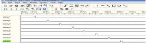
[image:2.595.319.552.153.257.2]The purpose of delay line is to generate the delay of 1ns. A delay equivalent to 7 times the input signal is obtained as shown in the figure (2) keeping space time constant at 1ns.
Fig. 2. Signal flow through delay line
2.4 ADC:
The analog signal is converted to digital signal using ADC. FMC108 (FPGA Mezzanine card) ADC is used for such conversion. FMC108 is having 8 A/D channels of 14 bit resolution and sampling rate of 250 MSPS (Mega Samples per Second).Internal clock used for this conversion is 250Mhz.Digitalisation of all 8 delayed signals is then followed by FPGA which analyses, stores and display the result.
2.5 Field Programming Gate Array:
FPGA processes the digital input signal. This gives the information about target such as range resolution and target discrimination. FPGA used for the signal processing in this work is Ultra Scale Kintex (xcu040). With 1920 DSP slices and 450 GPIOs, FPGA enables to execute DSP algorithm in either sequential or a parallel manner.
2.6 Processor:
The processor which meets all the specification of systems is E3800 Intel Atom processor. This processor can be can operated over variety of thermal condition.
High connectivity, integrated memory controller are some of features of this processor
[image:2.595.36.281.346.422.2]3.SIGNAL PROCESSING
Fig. 3. Signal processing in UWB radar
The signal processing module shown above has different algorithms such as wavelet transform, Fast Fourier transform, and constant false alarm rate. All these blocks are designed in such a way that various information related to target such as velocity, distance are obtained. Information about both stationary as well as non-stationary target can be obtained using this module.
3.1 Reconstruction:
Digital signal sampled by ADC serves as input to reconstruction block. Finite number of time delays are used to space the sample at the channel with effective delay of 1 ns. At the output of each channel, a total of 8 sampled signals are collected [6]. All these 8 samples are having a delay of 1ns each.
FIFO is temporary memory used for storing data. In FIFO the data first entered will be given out first. Two signal full and empty are used to signal the status of memory. A high on empty signal will write data into memory while a high on full signal will read the memory.
© 2019, IRJET | Impact Factor value: 7.211 | ISO 9001:2008 Certified Journal | Page 1160
Fig. 4. Reconstruction of signal & FIFO
3.2 Wavelet transform
Wavelets are zero mean extensively decaying oscillation having waveform like structure. Wavelet transform makes analysis about the presence of the target with the help of radar echoes [8]. Discrete wavelet transform is defined as:
Ajf =∑n€zh(n-2k)Aj-if
Djf =∑n€zh(n-2k)Dj-if (1)
Where g(n) and h(n) are high pass and low pass filter. Smoothening of abrupt data is done using low pass filter. Convolution of LPF and HPF coefficients is done with the samples from ADC. Excess of the data created during convolution is then removed by down sampling by a
factor of 2j. Discrete wavelet decomposition in shown in
[image:3.595.312.560.476.645.2]fig.(5).The output of DWT
Fig.5 Discrete Wavelet Decomposition
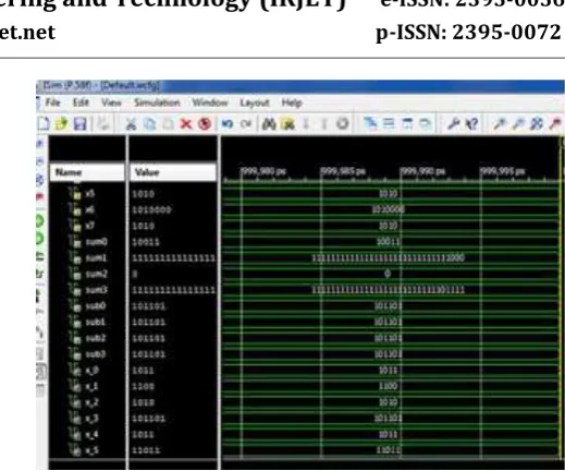
Fig (6) shows output of DWT. Sum0 to sub3 are the outputs at each level of the calculation for figure(5).
Fig. 6. Discrete Wavelet Transform
3.3 Fast Fourier Transform:
FFT algorithm can be used for determination of range profile and range resolution of radar. Collision probability is high for near target hence ADC samples are down sampled e.g. 1000 samples are de-interleaved to 500 samples processing through zero padding FFT which gives same result as the number of FFT points remains constant[11]. Using this de-interleaving technique data acquired by ADC can be sampled down to Ns/2 where Ns indicates total number of samples and also the ranges of the middle value samples can be adjusted. Initially 8 point FFT is used for resolving 8 samples from ADC using radix-
Stage1 Stage2 Stage3
Fig. 7. Butterfly Diagram for DIF FFT
[image:3.595.44.250.515.614.2]© 2019, IRJET | Impact Factor value: 7.211 | ISO 9001:2008 Certified Journal | Page 1161
[image:4.595.37.296.188.376.2]Input to the first stage, as shown in butterfly diagram is the reconstructed signal whose output then feeds as input for the stage 2. Stage 2 output is now the input for the third stage and third stage output serves as final FFT output in frequency domain. Fig (8) shows real part FFT output. Outre0, outre1....outre7 indicates the real part of output signals.
Fig. 8. Real part of FFT
Fig (9) shows imaginary part FFT output. outim1, outim2 ...outim7 indicates the imaginary part output signals
Fig. 9. Imaginary part of FFT
3.4 Constant False alarm rating:
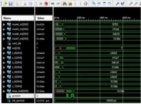
CFAR is an efficient way of detecting the target returns against interference of background noise and clutter. Certain threshold for the background noise can be determined and can be set as the reference value above which target will exist, if the target detection in background is constant in time and space [13]. If background is variable threshold value can be changed based on certain observation such as type of object, location, size, existence of different state of object. Algorithm used to adjust the digitized signal according to its magnitude is OS-CFAR. The reconstructed signal is divided into group of 4 elements on FPGA. Bubble sort
[image:4.595.315.561.227.408.2]algorithm is used for each group .Every value is compared with pre-determined threshold value after sorting [13]. Greater signal indicates final output. If value is above threshold then signal output will be one else zero. As shown in fig (10) FFT outputs are divided into two groups each consisting of 4 elements. This elements undergoes sorting in descending order of their magnitude. After sorting every element is compared with tested threshold value and if it is above threshold value of greater signal will be 1.
Fig. 10. Constant False alarm rating
4. CONCLUSION
[image:4.595.37.292.429.553.2]© 2019, IRJET | Impact Factor value: 7.211 | ISO 9001:2008 Certified Journal | Page 1162
ACKNOWLEDGEMENT
The authors would like to thank Dr. N.M.Singh, Head of Department and the entire Electrical department from VJTI Mumbai, India for providing facilities to carry out this research work and also would like to thanks Veermata Jijabai Technological Institute Mumbai India for support.
REFERENCES
[1]Rahul Tichkule, Mrs. Poornima shrivastava, Dr. R.G. karandikar,"Application of Time Delay Approach in Ultra Wide Band RADAR Processing", unpublished
[2]Jing Li, Lanbo Lui, Zhaofa Zeng, Fengshan Lui, "Simulation and signal processing of UWB radar for Human Detection in Complex Environment"14th International conference on ground penetrating radar 2012
[3]Chi-Hasuan, Yu-Fang Chiu, " A UWB Radar Signal Process Platform for Real Time Human Respiratory Feature Extraction Based on Four Signal Linear Extraction Model" IEEE Transaction on Biomedical Circuits and Systems
[4]Marco Govoni, Enrico M. Vitucci, Vittorio Degli Esposti, Francesco Guidi, Giovanni Tartarini, Davide Dardari"Study of a UWB Multi-static Radar for Railroad Crossing Surveillance", IEEE 2015
[5]Faheem Khan, Sung Ho Cho," A Detailed Algorithm for Vital Sign Monitoring of a Stationary/Non-Stationary Human through IR-UWB Radar", Sensors 2017, 17, 290
[6]Yin Jun, Deng Jia-Hao, “UWB Distance detector”
International Conference on Computational
Electromagnetic and its Applications Proceedings. 2004
[7]https://en.wikipedia.org/wiki/FIFO_(computing_and_ electronics)
[8]GuiFen Xia, BaoJun Zhao," Detection of Laser Radar Target Based on Wavelet Decomposition", ICSP2006 Proceedings
[9]S J Thiruvengadam, P Chinnadurai, M Thirumalai Kumar & V Abhaikumar," Signal Detection Algorithm using Discrete Wavelet Transform and Radon Transform", IETE Journal of Research
[10]https://en.wikipedia.org/wiki/Discrete_wavelet_tra nsform
[11]Eugin Hyun, Sang-Dong Kim, Chiho Park, Jong-Hun Lee," Automotive FMCW Radar with Adaptive Range Resolution", Second International Conference on Future
Generation Communication and Networking Symposia, 2008